Note: Descriptions are shown in the official language in which they were submitted.
CA 02590787 2007-06-11
WO 2006/063983 PCT/EP2005/056708
A PROTECTIVE CARRIER AND HANDLE FOR CANS
Technical Field of the Invention
The present invention relates to a carrier adapted to be used for all kinds of
drinks
and especially for carbonated drinks such as beer cans etc...
Background of the Invention / Prior Art
There is significant amount of work on can/bottle carriers in the patent
literature; in
a nutshell, all aiming at easing carriage of a plurality of cans/bottles by
one hand
and eliminating hygiene concerns, which are caused by storage environment dust
that is accumulating on the peripheral portions of can top surfaces around the
drinking mouth and thereby posing a serious risk.
Beside cardboard carriers to store and carry a plurality of cans at once,
polymer
based carriers were also very much worked to be satisfactorily commercialized
in
the market. Among patents/patent applications in the technical field, it is
possible to
cite numerous documents, for instance, to be of exemplary reasons, US 5 562
205,
WO 02/064433, US 3 346 106, WO 93/02942 and WO 98/05570 may be cited
here.
In the field, beside measures taken to eliminate hygiene concerns and
providing
necessary carrier means, another prior issue is to provide a carrier with an
optimum design so as to not occupy a volume much larger than that of the
original
product and which is significantly in the shape of the top surface of a can,
to be
hence suitable for storing cans one above another in a conventional manner. On
the other hand, needless to say that mechanical stability is always of major
importance, especially when a 3-liter, 6-piece beer pack is carried by a thin
polymer carrier, as is the situation for most of the cases.
There is one additional design aspect which should also be considered of
priority in
can carriers. According to the present invention and contrary to the
disclosure
proposed by the patent documents cited above, the can carriers are designed to
carry not only the full pack of can but also every single can one by one. In
other
words, the carrier assembly is designed in a detachable manner, as is the
practice
in the prior art, but also designed with means to carry single cans
separately. This
is especially advantageous in that one single can may be carried after
detaching
the same from the rest of the can pack.
CA 02590787 2009-06-29
52196-1
-2-
Objects of Some Embodiments of the Invention
One of the objects of some embodiments of the present invention is to provide
a
can carrier suitable for carrying a plurality of cans by one hand in a
comfortable
and reliable manner.
Another object of some embodiments of the present invention is to provide a
can
carrier with carrier means suitable for carrying full can pack or any number
of cans
detached from the rest of the pack as well.
Yet another object of some embodiments of the present invention is to provide
a
can carrier occupying a volume not much larger than that of the original
product
during transport, storage and exhibition, can's bottom surface fitting into
the top
surface of said can carrier, hence allowing storage of can packs back to back
and
one above another in a conventional manner.
Summary of the Invention
An aspect of the present invention relates to use of polymer-based circular
carrier
means mounted on can bodies in the manner to cover their entire top surfaces.
The circular carrier means are generally planar, sheet-like structures having
integral protruding members and recesses creating a corresponding surface for
receiving opposite can surface. Each carrier means is additionally provided
with a
handle means, normally encircling part of the periphery of said carrier means
and
separated therefrom by perforations. Each element of a six-element can pack,
provided in the form of two arrays of three cans in a typical manner,
comprises a
carrier means provided with a handle means for individual carriage as well as
for
carriage of the full can assembly by use of any of said handles. Said carrier
means are connected to neighboring carriers by perforations along peripheral
portions in the parts out of said handle perforations.
Another aspect of the present invention relates to a carrier suitable for
carrying a
can, comprising one circular, sheet-like carrier cell structure attached to a
top
surface of the can, wherein said carrier cell comprises; a carrier means
covering
and tightly gripping the top surface of the can by means of suitable integral
protruding members and recesses creating a corresponding surface for receiving
CA 02590787 2009-06-29
52196-1
- 2a -
gripping can surface, a handle means surrounding said carrier means along part
of the periphery of said carrier means and which is attached thereto by means
of a
detachable circular perforated line.
A further aspect of the present invention relates to a carrier suitable for
carrying a
plurality of cans, comprising at least one circular, sheet-like carrier cell
structure
attached to a top surface of the can and means to be connected to neighboring
cells wherein said carrier cell comprises; a carrier means covering and
tightly
gripping the top surface of the can by means of suitable integral protruding
members and recesses creating a corresponding surface for receiving gripping
can surface, a handle means surrounding said carrier means along part of the
periphery of said carrier means and which is attached thereto by means of a
detachable circular perforated line, at least a second detachable linear
perforated
line attached to a neighboring carrier cell along peripheral portions of said
carrier
means in parts out of said circular perforated line, whereby a plurality of
cans may
be carried together, one by one or in any desired number by detaching said
carrier
cells, by way of detaching any of said handle means in a carriage.
Brief Description of the Figures
In the following, the invention is described in more detail with reference to
the
drawings, which are given solely for the purpose of exemplifying the
invention.
According to the present invention, Fig. 1 is a perspective side view of a can
carrier comprising a pair of carrier cells with the handle means being not
detached
from the carrier means.
CA 02590787 2007-06-11
WO 2006/063983 PCT/EP2005/056708
-3-
Fig. 2 is a perspective side view of a single can carrier cell detached from
neighboring carrier cell with the handle means being not detached from the
carrier
means.
Fig. 3 is a top view of a single can carrier cell detached from neighboring
carrier
cell with the handle means being not detached from the carrier means.
Fig. 4 is a perspective side view of a can carrier comprising two pairs of
carrier
cells with the handle means being not detached from the carrier means.
Fig. 5 is a top view of a can carrier comprising one pair of carrier cells
with the
carrier means and the handle means being not detached from the neighboring
carrier cells and from the carrier means respectively.
Fig. 6 is a top view of a can carrier comprising three pairs of carrier cells
with the
carrier means and the handle means being not detached from the neighboring
carrier cells and from the carrier means respectively.
Fig. 7 is a top view of a can carrier comprising three pairs of carrier cells
with only
the carrier means located in the middle pair being provided with handle means.
Fig. 8 is a top view of a can carrier comprising two pairs of carrier cells
with the
carrier means and the handle means being not detached from the neighboring
carrier cells and from the carrier means respectively.
Fig. 9 is a top view of a can carrier comprising one pair of carrier cells
with the
handle means being detached from the carrier means.
Fig. 10 is a side view of a can carrier comprising one pair of carrier cells
with the
handle means being detached from the carrier means.
Fig. 11 is a perspective side view of a can carrier comprising one pair of
carrier
cells with the handle means being detached from the carrier means.
Fig. 12 is an another top side view of a can carrier comprising one pair of
carrier
cells with the handle means being detached from the carrier means.
CA 02590787 2007-06-11
WO 2006/063983 PCT/EP2005/056708
-4-
Fig. 13 is an another side view of a can carrier comprising one pair of
carrier cells
with the handle means being detached from the carrier means.
Fig. 14 is an another perspective side view of a can carrier comprising one
pair of
carrier cells with the handle means being detached from the carrier means.
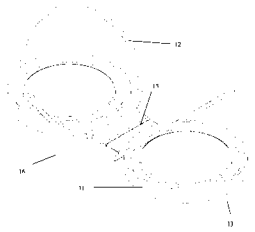
Fig. 15 is a perspective side view of a can carrier comprising o carrier cell
with the
handle means being not detached from the carrier means.
Detailed Description of the Invention
Now referring to the figures outlined above, the can carrier (16) according to
the
present invention employs polymer-based carrier cells (13) comprising carrier
means (11) in the form of planar and circular sheet-like structures covering
top
surfaces of can bodies and incorporating circular handle means (12)
surrounding
said carrier means (11) along part of their peripheral portions. Said handle
means
(12) are connected to said carrier means (11) by means of a circular
perforated line
(14) provided in between said carrier means (11) and said handle means (12)
along the periphery of said carrier means (11). Said handle means (12),
normally
lying adjacent to said carrier means (11) during transport, storage and
exhibition
may be easily separated therefrom by buyers prior to carrying.
It is known that carbonated drink cans generally have a cylindrical body. From
a
side view of a can body, however, it is seen that the lateral surface of the
same is
extending uprightly and then reaching the top surface of the can with a slight
inward slope. In other words, beverage can bodies' top surface areas are
smaller
than a given cross-sectional surface area that is located between the top and
bottom surfaces of the cylindrical body and that is parallel to those two.
According
to the present invention, a carrier cell (13), which is mounted on a single
can and
which comprises said carrier means (11) encircled by said handle means (12),
has
its outermost limits in the horizontal axis, within an area defined by the
vertical
projection lines of the lateral surface of the can body. Considering the fact
that can
packs are arranged in horizontal rows during transport, storage and
exhibition,
arranging those packs back to back would cause a space usage problem in case
said carrier cells' (13) outermost portions in the horizontal axis extend
beyond the
area defined by the vertical projection lines of the largest horizontal cross-
sectional
area of the can body. Due to this design characteristic according to the
present
invention, a can pack with every can having a carrier cell on the top surface,
CA 02590787 2007-06-11
WO 2006/063983 PCT/EP2005/056708
-5-
occupies the same volume compared to the volume occupied by a can pack
without any carrier cell in a conventional manner and hence poses no problem
with
regard to space usage during transport, storage and exhibition.
The carrier cells (13) according to the present invention are also convenient
for
arranging can packs one above another vertically during transport, storage and
exhibition since upper surfaces of said carrier cells (13) have suitable
recesses for
receiving bottom surfaces of the cans above.
Said carrier means (11) according to the present invention, tightly grips the
upper
surface of a can, through suitable recesses and protruding members provided in
the form to engage in the opposite surface on to which said carrier means is
mounted. Said carrier means (11), normally in a fixedly attached position to
the can
top surface, may be removed therefrom by the consumer, through exertion of a
limited hand force by the edge portions of said carrier cells (13) prior to
usage.
According to the present invention, every can in a can pack is provided with a
handle means (12) attached to said carrier means (11) by means of a circular
perforated line (14) provided along part of the periphery of said carrier
means (11)
and may easily be detached therefrom by way of pulling that out as those
handle
means are designed in the form of a tear-off ring. On the other hand, a
carrier
means (11) with its handle means (12) being detached, will still be fixedly
attached
to neighboring carrier means (12) by means of a second linear perforated line
(15)
in the remaining peripheral portion of said carrier means (11) and carrying a
can
pack by means of any of detached handle means (12) will hence be possible.
Perforations are provided at least at one point (18) thorough said circular
and linear
perforated lines (14 and 15 respectively).
According to this configuration, a user may either choose to carry a plurality
of
cans by an individual handle (12) provided on any of the cans in the pack or
detach
a number of desired cans by tearing off said perforated lines (15) in between
cells
(13) and carry the same by detaching any of the remaining handle means (12). A
carrier cell (13) detached from a can's top surface may still be reclosed and
the
half-full can may be safely closed and protected until the next time the user
drinks
it.
CA 02590787 2007-06-11
WO 2006/063983 PCT/EP2005/056708
-6-
The present invention thus enables both individual carriage of a single can
and
plural carriage of the full pack or any number of cans detached from the pack,
by
means of any of the available handle means (12).
According to Fig. 7, which demonstrates another embodiment of the present
invention, it is seen that only a pair of carrier cells (13) is provided with
the handle
means (12) instead of every single cell (13). However, it is of primary object
of this
invention to provide a separate handle means (12) to every carrier cell (13).
Additionally, as is seen in Fig. 6 or Fig. 7, a can pack may also be carried
in a
conventional manner by two apertures (17) provided in the center of each cell
(13)
group in the form of a square consisting of 4 cells (13).
According to the present invention, the cans provided with said handle means
(12)
may be hanged on a rack or on a wall for exhibition through said handle means
(12) as well as on a rucksack as an accessory item.