Note: Descriptions are shown in the official language in which they were submitted.
CA 02590958 2007-06-04
ARTICULATING BLUNT DISSECTOR/GASTRIC BAND
APPLICATION DEVICE
BACKGROUND OF THE INVENTION
1. Field of the Invention
The invention relates to a gastric band application device. More particularly,
the invention relates to an articulating blunt dissector/gastric band
application device.
2. Description of the Prior Art
Morbid obesity is a serious medical condition. In fact, morbid obesity has
become highly pervasive in the United States, as well as other countries, and
the trend
appears to be heading in a negative direction. Complications associated with
morbid
obesity include hypertension, diabetes, coronary artery disease, stroke,
congestive
heart failure, multiple orthopedic problems and pulmonary insufficiency with
markedly decreased life expectancy. With this in mind, and as those skilled in
the art
will certainly appreciate, the monetary and physical costs associated with
morbid
obesity are substantial. In fact, it is estimated the costs relating to
obesity are in
excess of 100 billion dollars in the United States alone.
A variety of surgical procedures have been developed to treat obesity. The
most common currently performed procedure is Roux-en-Y gastric bypass (RYGB).
1
CA 02590958 2007-06-04
This procedure is highly complex and is commonly utilized to treat people
exhibiting
morbid obesity. Other forms of bariatric surgery include Fobi pouch, bilio-
pancreatic
diversion, and gastroplastic or "stomach stapling". In addition, implantable
devices
are known which limit the passage of food through the stomach and affect
satiety.
In view of the highly invasive nature of many of these procedures, efforts
have
been made to develop less traumatic and less invasive procedures. Gastric-
banding is
a type of gastric reduction surgery attempting to limit food intake by
reducing the size
of the stomach. In contrast to RYGB and other stomach reduction procedures,
gastric-banding does not require the alteration of the anatomy of the
digestive tract in
the duodenum or jejunum.
Since the early 1980s, gastric bands have provided an effective alternative to
gastric bypass and other irreversible surgical weight loss treatments for the
morbidly
obese. Several alternative procedures are performed under the heading of
gastric-
banding. Some banding techniques employ a gastric ring, others use a band,
some use
stomach staples and still other procedures use a combination of rings, bands
and
staples. Among the procedures most commonly performed are lap band, vertical
banded gastroplasty (VBG), silastic ring gastroplasty (SRG), and adjustable
silastic
gastric banding (AGB).
In general, the gastric band is wrapped around an upper portion of the
patient's
2
CA 02590958 2007-06-04
. .
stomach, forming a stoma that is less than the normal interior diameter of the
stomach. This restricts food passing from an upper portion to a lower
digestive
portion of the stomach. When the stoma is of an appropriate size, food held in
the
upper portion of the stomach provides a feeling of fullness that discourages
overeating.
Typically, the gastric band is laparoscopically introduced into a patient's
abdomen by pushing it through a trocar. A variety of delivery devices have
been
developed for this purpose. However, currently available delivery devices
exhibit
many shortcomings, including, but not limited to the fact that they are
difficult to
sterilize, require two hands for proper operation thereof and exhibit weakness
when
moved in key directions. As such, a need currently exists for improved gastric
band
delivery systems providing for convenient and reliable delivery of gastric
bands. The
present invention provides such a gastric band delivery technique.
3
CA 02590958 2007-06-04
. .
SUMMARY OF THE INVENTION
It is, therefore, an object of the present invention to provide a single
handed
articulating blunt dissector/gastric band application device. The device
includes a
support shaft connecting a handle at a first end of the device to an
articulating
assembly at a second end of the device. The handle includes an actuation
mechanism
linked to the articulating assembly for controlling movement thereof. The
second end
includes a proximal end and a distal end, wherein the distal end includes a
blunt distal
tip shaped and dimensioned for dissecting tissue without unduly causing trauma
to the
tissue. The second end also includes a suture grasping notch shaped and
dimensioned
for engaging and pulling a gastric band.
It is also an object of the present invention to provide a device wherein the
suture grasping notch is obliquely oriented relative to a longitudinal axis of
the device.
It is another object of the present invention to provide a device wherein the
suture grasping notch is oriented at a 45 degree angle relative to the
longitudinal axis
of the device.
It is a further object of the present invention to provide a device wherein
the
articulating assembly is proximally oriented relative to the suture grasping
notch.
4
CA 02590958 2007-06-04
. .
It is also another object of the present invention to provide a device wherein
the articulating assembly includes a flex member composed of a first side
member and
a second side member.
It is yet another object of the present invention to provide a device wherein
the
first side member and the second side member are substantially parallel and
are
spaced from each other as they extend along the second end of the device.
It is also an object of the present invention to provide a device wherein the
first
side member includes an inner surface with a plurality of necked down regions
and
the second side member includes an inner surface with a plurality of necked
down
regions.
It is also a further object of the present invention to provide a device
wherein a
constraining band is fitted about the flex member.
It is yet a further object of the present invention to provide a device
wherein
the actuation mechanism includes a flexing finger which one may hold and move
to
cause articulation of the articulating assembly.
It is also an object of the present invention to provide a device wherein the
flexing finger includes a constant stress beam having a tapered down cross
section as
it extends from a second end of the handle to a first end of the handle so
that the
flexing finger bends down in a smooth arc.
CA 02590958 2007-06-04
It is another object of the present invention to provide a device wherein the
actuation mechanism includes a cable having a first end and a second end, the
first
end of the cable being coupled to the flexing finger and the second end being
coupled
adjacent the articulation assembly such that the cable moves to cover the
increased arc
length over which it is stretched as the flexing finger is bent.
It is a further object of the present invention to provide a device including
first
and second pulleys about which the cable is wrapped for amplifying the
displacement
of the cable.
Other objects and advantages of the present invention will become apparent
from the following detailed description when viewed in conjunction with the
accompanying drawings, which set forth certain embodiments of the invention.
6
CA 02590958 2007-06-04
. ,
BRIEF DESCRIPTION OF THE DRAWINGS
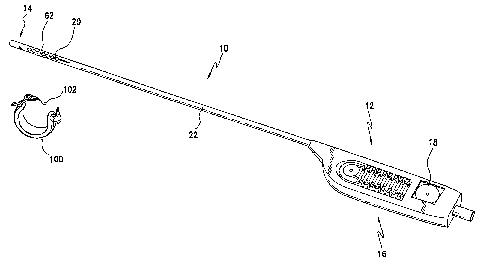
Figure 1 is a perspective view of the present single handed articulating blunt
dissector/gastric band application device.
Figure 2 is a detailed view of the second end of the application device shown
with reference to Figure 1 wherein the constraining band has been removed.
Figure 3 is a detailed view of the first end of the application device shown
with
reference to Figure 1.
7
CA 02590958 2007-06-04
DESCRIPTION OF THE PREFERRED EMBODIMENTS
The detailed embodiments of the present invention are disclosed herein. It
should be understood, however, that the disclosed embodiments are merely
exemplary of the invention, which may be embodied in various forms. Therefore,
the
details disclosed herein are not to be interpreted as limiting, but merely as
the basis for
the claims and for teaching one skilled in the art how to make and/or use the
invention.
Referring to Figures 1, 2 and 3, a single handed articulating blunt
dissector/gastric band application device 10 is disclosed. The device 10
includes a
first end 12 and a second end 14. The first end 12 is generally composed of
the
handle 16 and actuation mechanism 18 which are described below in greater
detail.
The second end 14 is composed of an articulating assembly 20 adapted for
dissecting
tissue, as well as engaging and manipulating a gastric band 100 during
delivery thereof.
Between the first and the second ends 12, 14 of the present device 10 is a
support
shaft 22 that connects the handle 16 at the first end 12 of the device 10 to
the
articulating assembly 20 at the second end 14 of the device 10. As those
skilled in the
art will appreciate, the present device 10 may be manufactured from a variety
of
biocompatible materials adapted for the specific purposes of the present
invention.
As will be appreciated based upon the following disclosure, the second end 14
8
CA 02590958 2014-01-08
of the present device 10 includes a proximal end 24 and a distal end 26. The
distal
end 26 includes a blunt distal tip 28 shaped and dimensioned for dissecting
tissue
without unduly causing trauma to the tissue. Also at the distal end 26 of the
second
end 14 of the present device 10, and adjacent the distal tip 28, the second
end 14 is
provided with a suture grasping notch 30 for engaging and pulling the gastric
band
100 through the retrogastric esophageal window. Referring to commonly owned
U.S.
Patent No. 5,522,788 entitled "Finger-like laparoscopic blunt dissector
device", gastric
bands 100 are commonly provided with a suture loop 102 extending therefrom.
The
suture loop 102 provides a contact member allowing one to grasp the end of the
gastric band 100 and draw it about the stomach for application thereof.
With this in mind, the second end 14 of the present application device 10 is
provided with a notch 30 shaped and dimensioned for receiving the suture loop
102
in a manner allowing one to readily manipulate the gastric band 100 as it is
applied
about the stomach. In accordance with a preferred embodiment, the notch 30 is
obliquely oriented relative to the longitudinal axis 32 of the present device
10 (that is,
when it is in its straight configuration). More particularly, the notch 30 is
oriented at a
45 degrees angle relative to the longitudinal axis 32 of the device 10 with
the angular
orientation directed toward the first end 12 of the device 10. As mentioned
above, an
9
CA 02590958 2007-06-04
articulating assembly 20 is positioned at the second end 14 of the device 10.
The
articulating assembly 20 is, however, proximally oriented relative to the
notch 30
described above such that the articulating assembly 20 can be used to reorient
the
notch 30 for use thereof in wrapping a gastric band 100 about an individual's
stomach. In general, the articulating assembly 20 is positioned between the
proximal
end 24 and the distal end 26 of the second end 14 of the present device 10.
The
articulating assembly 20 includes a flex member 34. The flex member 34 is
composed
of a single piece of flexible material, which is capable of bending as one
side thereof is
moved relative to the other side. In accordance with a preferred embodiment,
the
flexible material is nylon, although polyethylene and polypropylene are also
good
materials for use in the construction of the flexible material. Although
specific
materials are disclosed herein, other flexible materials could certainly be
used without
departing from the spirit of the present invention. More particularly, the
flex member
34 includes a first side member 36 and a second side member 38. The first side
member 36 and the second side member 38 are substantially parallel and are
spaced
from each other as they extend along the second end 14 of the present device
10.
The first and second side members 36, 38 are relatively moveable to create the
flex
characteristics discussed below in greater detail.
The first side member 36 of the flex member 34 includes a first end 40 and a
CA 02590958 2007-06-04
second end 42, while the second side member 38 of the flex member 34 includes
a
first end 44 a second end 46. The first ends 40, 44 of the respectively first
and second
side members 36, 38 of the flex member 34 are coupled to define the distal end
48 of
the flex member 34, and ultimately extend into the distal end 26 of the second
end 14
of the present device 10, which includes the previously discussed suture loop
grasping
notch 30 as discussed above.
The first side member 36 includes a substantially smooth outer surface 50. The
inner surface 52 of the first side member 36 includes a plurality of necked
down
regions 54. The necked down regions 54 reduce the strength of the first side
member
36 at predetermined locations therealong and facilitate bending by minimizing
the
articulation force required for movement thereof. Similarly, the second side
member
38 includes a substantially smooth outer surface 56. The inner surface 58 of
the
second side member 38 includes a plurality of necked down regions 60. The
necked
down regions 60 reduce the strength of the second side member 38 at
predetermined
locations therealong and facilitate bending by minimizing the articulation
force
required for movement thereof. While the necked down regions 54, 60 of the
first
and second side members 36, 38 allow for controlled flexing of the flex member
34,
the smooth outer surfaces 50, 56 allow for movement of the present device 10
through body cavities and tissue without causing undue trauma to the adjacent
tissue.
11
CA 02590958 2007-06-04
In order to prevent the first and second side members 36, 38 from bending
away from each other as loads are applied thereto in accordance with the
present
invention, a constraining band 62 is fitted about the flex member 34. The
constraining band 62 flexes with the flex member 34 and moves therewith for
preventing the first and second side members 36, 38 of the flex member 34 from
separating. Although a constraining band 62 is disclosed in accordance with a
preferred embodiment of the present invention, other constraining members, for
example, an extension spring may be utilized without departing from the spirit
of the
present invention. The utili7ation of a constraining band 62 (or other
constraining
structure) is critical in allowing the flex member 34 to apply force in the
direction in
which it is flexed as well as in the opposite direction, without the first and
second side
members 36, 38 bowing outwardly upon the application of tension causing
flexing of
the present articulating assembly 20. By utilizing the constraining band 62,
the flex
member 34 is symmetrical and may flex in either direction, providing greater
than 180
of articulation.
As mentioned above, the first end 12 of the device 10 is provided with the
actuation mechanism 18 used in controlling flexing of the flex member 34. The
actuation mechanism 18 includes a flexing finger 64 integrally formed with the
handle
12
CA 02590958 2007-06-04
16. The flexing finger 64 is generally a readily flexible, elongated member
which one
may hold and move to cause articulation of the flex member 34 described above.
More particularly, the handle 16 is formed with a central opening 80 in which
the flexing finger 64 is positioned. The central opening 80 includes a first
end 82 and
a second end 84 with the first end 86 of the flexing finger 64 being coupled
to the
handle 16 at the first end 82 of the central opening 80. The remainder of the
flexing
finger 64 is spaced from the handle 16. As such, the flexing finger 64 may
bend about
the first end 86 thereof, and within the central opening 80, as pressure is
applied along
the second end 88 of the flexing finger 64.
In accordance with a preferred embodiment, the flexing finger 64 is composed
of nylon, although polyethylene and polypropylene are also good materials for
use in
the construction of the flexible material. Although specific materials are
disclosed
herein, other flexible materials could certainly be used without departing
from the
spirit of the present invention. As will be better appreciated based upon the
following
disclosure, the flex finger 64 uses a constant stress beam (tapered down cross
section)
so that flexing finger 64 bends down in a smooth arc along the length of the
flexing
finger 64 and stress is not concentrated at either the first end 86 or the
second end 88
of the flexing finger 64.
13
CA 02590958 2007-06-04
A pull cable 66 is slideably coupled to the flexing finger 64 such that the
cable
66 moves to cover the increased arc length over which it is stretched as the
flexing
finger 64 is bent. In addition to the cable 66, and in accordance with a
preferred
embodiment, pulleys 68, 70 are used to amplify the displacement of the cable
articulating the flex member 34. The pulleys, for example, a first, or palm,
pulley 68,
which is positioned at the first end 72 of the handle 16 adjacent the first
end 86 of the
flex finger 64, and a second, or tip pulley 70, which is positioned at the
second end 88
of the flex finger 64, may be static or free spinning. The pull cable 66 winds
around
the palm pulley 68 and extends to the first end 72 of the handle 16 where it
is
anchored. In this way, motion of the cable 66 translates into motion of the
elements
of the flexing finger 64, thereby articulating the flex member 34.
More particular, and in accordance with a preferred embedment, the cable 66
includes a first end 74 and a second end 76. The first end 74 is fixedly
secured to the
first end 72 of the handle and the second end 76 is fixedly secured to the
second end
14 of the device 10 at a position beyond the flex member 34. The cable 66 is
of a
length such that it is slightly taut when the device 10 is straight and is
tensioned when
the flexing finger 64 is bent in a predetermined direction (as those skilled
in the art
will appreciate, and in accordance with a preferred embodiment, the cable 66
is
loosened when the flexing finger 64 is bent in the other direction).
14
CA 02590958 2007-06-04
The flexing finger 64 and fixing point of the first end 74 of the cable 66
allow
one to readily alter the effective length between the fixing point of the
cable 66 at the
second end 14 of the device 10 and the fixing point of the cable 66 at the
first end 12
of the device 10. In particular, because the cable 66 is oriented over an
outer surface
of the flexing finger 64, when one bends the flexing finger 64 into a concave
orientation when viewed from the side along which the cable 66 extends, the
effective
distance between the fixing point of the cable 66 at the second 14 end of the
present
device 10 and the fixing point of the cable 66 at the first end 12 of the
device 10
increases, creating increased tension along the cable 66 and causing the flex
member
34 to flex in the direction of the applied tension. Conversely, when one bends
the
flexing finger 64 into a convex orientation when viewed from the side along
which the
cable 66 extends, the effective distance between the fixing point of the cable
66 at the
second end 14 of the present device 10 and the fixing point of the cable 66 at
the first
end 12 of the device 10 decreases, creating slack along the cable 66 and
allowing it to
remain in its relaxed configuration, which, in accordance with a preferred
embodiment of the present invention, is straight.
Bending of the flex member 34, and the creation of tension, is further
enhanced by the provision of a pulley system along the length of cable 66. In
particularly, first and second pulleys 68, 70 are respectively placed at the
first end 72
CA 02590958 2007-06-04
of the handle 16 adjacent the first end 86 of the flexing finger 64 and the
second end
88 of the flexing finger 64. The cable 66 is looped through the first and
second
pulleys 68, 70 adjacent the first end 74 thereof. In accordance with a
preferred
embodiment, and beginning at the first end 74 of the cable 66, the cable 66
extends
up along the flexing finger 64 and is wrapped about the second pulley 70. The
cable
66 continues back toward the first end 72 of the handle 16 and wraps about the
first
pulley 68. The cable 66 then extends up along the device 10 where the second
end 76
of the cable 66 is secured at the second end 14 of the present device 10 at a
position
distal to the flex member 34 thereof.
In accordance with an alternate embodiment, the palm pulley may be a pinion
such that rotary motion of the palm pulley moves a rack longitudinally along
the shaft.
This would create a push-pull configuration capable of both articulating and
straightening the tip.
Through implementation of the present device 10, one may control the
movement of the flex member 34 by simply flexing the flexing finger 64 in a
manner
similar to the flexation he/she wishes to create at the second end 14 of the
present
device 10. In fact, the present device 10 may be calibrated such that the
flexing of the
flexing finger 64 substantially corresponds to the flexing at the flex member
34 at the
second end 14 of the device 10.
16
CA 02590958 2014-01-08
As mentioned above, the device is particularly adapted for delivery,
manipulation and application of gastric bands about the stomach of an
individual.
With this in mind, a gastric band 100 is inserted behind the stomach and the
first and
second ends thereof are manipulated with the present device until the band is
securely
positioned about the stomach. The present device is adapted for use with a
variety of
gastric bands, for example, those disclosed in commonly owned and copending
U.S.
Patent Application Serial No. 11/364,362, entitled "Gastric Band". It will
become
readily apparent to those skilled in the art that the above invention has
equal
applicability to other types of implantable bands. For example, bands are used
for the
treatment of fecal incontinence. One such band is described in U.S. Patent No.
6,461,292. Bands can also be used to treat urinary incontinence. One such band
is
described in U.S. Patent Application Publication No. 2003/0105385. Bands can
also
be used to treat heartburn and/or acid reflux. One such band is described in
U.S.
Patent No. 6,470,892. Bands can also be used to treat impotence. One such band
is
described in U.S. Patent Application Publication No. 2003/0114729.
While the preferred embodiments have been shown and described, it will be
17
CA 02590958 2007-06-04
. ,
understood that there is no intent to limit the invention by such disclosure,
but rather,
it is intended to cover all modifications and alternate constructions falling
within the
spirit and scope of the invention.
18