Language selection

Search

Patent 2590969 Summary

Third-party information liability

Some of the information on this Web page has been provided by external sources. The Government of Canada is not responsible for the accuracy, reliability or currency of the information supplied by external sources. Users wishing to rely upon this information should consult directly with the source of the information. Content provided by external sources is not subject to official languages, privacy and accessibility requirements.

Claims and Abstract availability

Any discrepancies in the text and image of the Claims and Abstract are due to differing posting times. Text of the Claims and Abstract are posted:

  • At the time the application is open to public inspection;
  • At the time of issue of the patent (grant).
(12) Patent: (11) CA 2590969
(54) English Title: INTERPROXIMAL DENTAL TOOL
(54) French Title: INSTRUMENT DENTAIRE INTERPROXIMAL
Status: Granted
Bibliographic Data
(51) International Patent Classification (IPC):
  • A61C 3/00 (2006.01)
  • A61C 15/04 (2006.01)
  • B29C 45/14 (2006.01)
(72) Inventors :
  • KHOURI, LOUIE (United States of America)
(73) Owners :
  • KHOURI, LOUIE (United States of America)
(71) Applicants :
  • KHOURI, LOUIE (United States of America)
(74) Agent: GOWLING WLG (CANADA) LLP
(74) Associate agent:
(45) Issued: 2014-12-02
(86) PCT Filing Date: 2005-12-08
(87) Open to Public Inspection: 2006-06-15
Examination requested: 2011-11-28
Availability of licence: N/A
(25) Language of filing: English

Patent Cooperation Treaty (PCT): Yes
(86) PCT Filing Number: PCT/US2005/044580
(87) International Publication Number: WO2006/063214
(85) National Entry: 2007-06-07

(30) Application Priority Data:
Application No. Country/Territory Date
11/008,805 United States of America 2004-12-09

Abstracts

English Abstract


The present invention relates to a hand held interproximal dental tool for
detaching unwanted materials from a
patient's teeth and to methods of manufacturing such tools. The interproximal
dental tool includes a compact, ergonomically designed
housing which is gripped by a dental practitioner during use and a blade
extending from and structurally supported by the housing
which includes serration' s for cutting or abrasive materials for sanding
unwanted material.


French Abstract

La présente invention porte sur un instrument dentaire interproximal manuel destiné à retirer des matières non désirées dans les dents d'un patient et sur les procédés de fabrication de ces instruments. L'instrument dentaire interproximal comprend un logement compact, de forme ergonomique, manipulé par le chirurgien dentiste et une lame s'étendant depuis ce logement et supporté structurellement par ce logement et comportant des dents ou des matériaux abrasifs pour couper ou abraser les matières non désirées.

Claims

Note: Claims are shown in the official language in which they were submitted.


8
CLAIMS
1. An interproximal dental tool comprising:
at least one blade; and
a thermoplastic housing molded over said blade, said housing including a body
sized to fit substantially within a patient's mouth, having spaced apart first
and
second ends, a curved terminal edge extending between said first and second
ends and an outer edge which is thicker than the curved terminal edge;
whereby said at least one blade includes a first edge area extending along the

length of said at least one blade which is permanently embedded within said
molded housing and an exposed portion extending from the curved terminal
edge and between the first and second ends, said exposed portion including a
leading edge area including serrations for detaching unwanted dental material
from teeth, wherein said at least one blade including serrations is designed
for
use within an interproximal space between teeth, and said curved terminal edge

of the housing provides a stop which upon complete insertion between the teeth

limits insertion of the at least one blade between the teeth such that said at

least one blade cannot reach the gum line.
2. The interproximal dental tool of Claim 1, wherein said at least one
blade
includes first and second blades, wherein one of said first and second blades
includes said serrations, and wherein one of said first and second blades
includes a band of abrasive material disposed along at least one side of a
blade.
3. The interproximal dental tool of Claim 2 wherein said band of abrasive
material is discontinuous thereby providing an abrasive free gap.
4. The interproximal dental tool of Claim 2 wherein said band of abrasive
material includes multiple sections having different grit.

9
5. The interproximal dental tool of Claim 1 wherein said housing is
substantially U-shaped and includes an outer edge and first and second side
walls.
6. The interproximal dental tool of Claim 5 wherein said side walls taper
inwardly from said outer edge to said curved terminal edge.
7. The interproximal dental tool of Claim 5 wherein said side walls are
concaved between said first and second ends along said outer edge.
8. The interproximal dental tool of Claim 5 wherein said outer edge
includes
outwardly projecting ribs along the first and second ends for enhanced
gripping
along said outer edge.
9. The interproximal dental tool of claim 1 wherein said at least one blade

includes a first blade disposed along one side of said housing and a second
blade disposed along a second side of said housing, at least one of said first

and second blades including said serrations for detaching unwanted material
from teeth.
10. The interproximal dental tool of claim 9 wherein at least one of said
first
and second blades includes a band of abrasive material disposed along at least

one side of a blade in proximity to the leading edge area.
11. The interproximal dental tool of claim 9 wherein said housing includes
first and second opposing substantially U-shaped portions.
12. A method of manufacturing an interproximal dental tool comprising:
a. positioning at least one blade including a first edge area along the
length
thereof and means for detaching unwanted material from teeth within an
injection molding cavity; and
b. injecting thermoplastic material into the molding cavity such that a
housing body sized to fit substantially within a patient's mouth having an
outer

10
edge, first and second side walls that taper inwardly from said outer edge to
a
curved terminal edge, and spaced apart first and second ends which define at
least one recess into which the at least one blade projects, wherein said
curved
terminal edge extending between said first and second ends is formed around
the blade permanently embedding a substantial portion of a blade along
substantially the entire first edge area and leaving the means for detaching
unwanted material from teeth freely exposed whereby said curved terminal
edge of the housing provides a stop which upon complete insertion between the
teeth, limits insertion of the at least one blade between the teeth such that
said
at least one blade cannot reach the gum line.
13. The method of Claim 12 wherein the portion of the blade which is
embedded in the housing includes a plurality of apertures through which said
thermoplastic material penetrates to enhance fixation of the blade.
14. The method of Claim 12 wherein said side walls taper inwardly from said

outer edge to said curved terminal edge.
15. The method of Claim 12 wherein said side walls are concaved between
said first and second ends of said housing.
16. The method of Claim 12 wherein said outer edge includes outwardly
projecting ribs along the first and second ends for enhanced gripping along
said
outer edge.
17. The method of Claim 12 wherein said means for detaching unwanted
material are selected from the group consisting of serrations projecting from
said leading edge area and a band of abrasive material disposed along at least

one side of a blade in proximity to the leading edge area.

11
18. The method of Claim 17 wherein said means for detaching unwanted
material includes said band of abrasive material, and wherein said band of
adhesive material is discontinuous thereby providing an abrasive free gap.
19. The method of Claim 18 wherein said band of abrasive material includes
multiple sections having different grit.
20. The method of claim 12 wherein said at least one blade includes a first

blade disposed along one side of said housing and a second blade disposed
along a second side of said housing, each of said blades including means for
detaching unwanted material from teeth.
21. An interproximal dental tool comprising:
a blade; and
a thermoplastic housing molded over said blade, said housing including a body
sized to fit substantially within a patient's mouth, having spaced apart first
and
second ends, a curved terminal edge extending between said first and second
ends and an outer edge which is spaced apart from and thicker than the curved
terminal edge;
whereby said blade includes a first edge area extending along the length of
the
blade which is permanently embedded within said molded housing and an
exposed portion extending from the curved terminal edge and between the first
and second ends, said exposed portion including a band of abrasive material on

at least one side of said blade for detaching unwanted dental material from
teeth, wherein said blade having said band of abrasive material is designed
for
use within an interproximal space between teeth and said curved terminal edge
of the housing provides a stop which upon complete insertion between the
teeth, limits insertion of the blade between the teeth such that said blade
cannot
reach the gum line.

12
22. The interproximal dental tool of Claim 21 further comprising a second
blade including serrations projecting from a leading edge area of the second
blade.
23. The interproximal dental tool of Claim 21 wherein said band of abrasive

material is discontinuous thereby providing an abrasive free gap.
24. The interproximal dental tool of Claim 21 wherein said band of abrasive

material includes multiple sections having different grit.
25. The interproximal dental tool of Claim 21 wherein said housing is
substantially U-shaped and includes an outer edge and first and second side
walls.
26. The interproximal dental tool of Claim 25 wherein said outer edge
includes outwardly projecting ribs along the first and second ends for
enhanced
gripping along said outer edge.
27. The interproximal dental tool of Claim 22 wherein said first blade is
disposed along one side of said housing and said second blade is disposed
along a second side of said housing.
28. The interproximal dental tool of Claim 21 wherein said housing includes

first and second opposing substantially U-shaped portions.
29. The interproximal dental tool of Claim 1, wherein the distance from the

first edge area of the blade to the leading edge area of the blade is no
greater
than 0.4 inches.
30. The interproximal dental tool of Claim 1, wherein the interproximal
dental
tool is sized to fit entirely within a patient's mouth.

13
31. The interproximal dental tool of Claim 21, wherein the distance from
the
first edge area of the blade to the leading edge area of the blade is no
greater
than 0.4 inches.
32. The interproximal dental tool of Claim 21, wherein the interproximal
dental tool is sized to fit entirely within a patient's mouth.

Description

Note: Descriptions are shown in the official language in which they were submitted.


CA 02590969 2007-06-07
WO 2006/063214 PCT/US2005/044580
INTERPROXIMAL DENTAL TOOL

BACKGROUND OF THE INVENTION
[0001] 1. Field of the Invention
[0002] The present invention relates to an interproximal dental tool,
and more particularly, an interproximal dental tool for detaching unwanted
material from teeth.
[0003] 2. Discussion of Prior Art
[0004] Interproximal dental tools which are currently in use for
detaching unwanted material by and large are ineffective, are often difficult
to
use and far too often lead to injuries to the patient or dental practitioner.
For
example, interproximal dental tools in the form of dental saws currently are
elongated, flexible, thin metal strips having a serrated edge which is
inserted
between the teeth to remove excess or unwanted material. This type of tool is
operated by gripping each end and working the tool back and forth between
the teeth in order to cut away the undesired material. As such, the dental
practitioner must insert at least one hand into a patient's mouth which
results
in discomfort to the patient. Worse yet, in the event that the tool is used on
teeth posterior to the incisors, it may be required that both of the dentist's
hands are at least partially inserted into the patient's mouth which is even
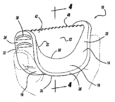
more uncomfortable.
[0005] Another perceived problem with the prior art dental saws is
that far too often injury results at least in part due to the flexible nature
of the
thin metal strip material. Because it is difficult to control the depth of
insertion
between the teeth, particularly the teeth in the posterior region of the
mouth, it
is not uncommon to lacerate the gum tissue with this type of prior art device.
Additionally, because the serrated edge of the tool extends virtually its
entire
length, far too often the dental practitioner's hands are injured when
handling
the device.
[0006] Still another perceived problem relates to the overall
effectiveness of the prior art tool. Because the tool is highly flexible to
allow
1


CA 02590969 2007-06-07
WO 2006/063214 PCT/US2005/044580
for the insertion between the teeth, an inherent drawback is the difficulty in
generating sufficient leverage on the tool when in use to effectively remove
unwanted material.
[0007] In view of the foregoing it is readily apparent there is a need
in the art for an improved interproximal dental tool which is effective at
removing unwanted material, easier to use, and less likely to result in injury
to
the patient or dental practitioner during use.

SUMMARY OF THE INVENTION
[0008] In accordance with the present invention, there is provided
an interproximal dental tool for detaching material from teeth comprising:
[0009] a housing, including a body, having spaced first and
second ends; and
[0010] a blade fixedly attached to said housing and extending
between the first and second ends, said blade including a leading portion
having means for detaching material from teeth.
[0011] Examples of unwanted materials which can be detached
from the teeth are materials used to repair teeth or used in cosmetic dental
procedures. Such materials include by way of non-limiting example, cements,
ceramics, composites, thermoplastics, and adhesives. Other unwanted
materials may include calculus.
[0012] Further areas of applicability of the present invention will
become apparent from the detailed description provided hereinafter. It should
be understood that the detailed description and specific examples, while
indicating the preferred embodiment of the invention, are intended for
purposes of illustration only and are not intended to limit the scope of the
invention.

BRIEF DESCRIPTION OF THE DRAWINGS
[0013] The present invention will become more fully understood
from the detailed description and the accompanying drawings, wherein:

2


CA 02590969 2007-06-07
WO 2006/063214 PCT/US2005/044580
[0014] Figure 1 is a perspective view of an interproximal dental tool
in accordance with the teachings of the present invention;
[0015] Figure 2 is a side view of the interproximal dental tool of
Figure 1;
[0016] Figure 3 is an end view of interproximal dental tool of Figure
1;
[0017] Figure 4 is a cross sectional view taken along lines 4-4 of the
interproximal dental tool of Figure 1;
[0018] Figure 5 is a side view of interproximal dental tool of Figure 1
depicting a blade imbedded within the molded handle;
[0019] Figure 6 is a top view of the interproximal dental tool of
Figure 1;
[0020] Figure 7 is a perspective view of an alternative embodiment
of an interproximal dental tool in accordance with the teachings of the
present
invention;
[0021] Figure 8 is a perspective view of still another alternative
embodiment of an interproximal dental tool in accordance with the teachings
of the present invention;
[0022] Figure 9A is a top view of the interproximal dental tool of
claim 8;
[0023] Figure 9B is a bottom view of the interproximal dental tool of
claim 8; and
[0024] Figure 10 is an end view of the interproximal dental tool of
claim 8.

DETAILED DESCRIPTION OF THE PREFERRED EMBODIMENTS
[0025] The following description of various embodiments is merely
exemplary in nature and is in no way intended to limit the invention, its
application, or uses.
[0026] Generally, the present invention describes a new and
improved interproximal dental tool which is easy to use, effective and
inexpensive to manufacture. Referring to Figures 1-6, a first embodiment of
3


CA 02590969 2007-06-07
WO 2006/063214 PCT/US2005/044580
an interproximal dental tool 10 contemplated under the present invention
includes as its major components, a blade 12 which is fixedly attached to a
housing 14. The housing 14 which serves as a handle for gripping the tool
along the outer edge 16 and/or along the respective opposing side walls 18
and 18a depending upon which teeth are being worked on, has a substantially
U-shaped body 20 which results in a recess 22 extending from a first end 24
of the housing 14 to a second end 24a. Disposed within the recess 22 is
blade 12 which extends from the first end 24 to the second end 24a of the
housing 14. As will be described in greater detail below, the housing 14 is
generally formed from a suitable injection moldable thermoplastic material
which has a relatively high coefficient of friction to enhance gripping of the
interproximal dental tool during use.
[0027] The housing is ergonomically sized to be conveniently used
between the practitioner's index finger and thumb as shown in phantom in
Figure 1. For example, the length of the tool from the first end 24 to the
second end 24a along the leading edge 42 is generally no more than about
1.25 inch. The height dimension of the dental tool as measured from the
center point 34 of the housing base 26 to the leading edge 42 of the blade 12
along center line 4-4 is generally no more than about 0.75 inches. Likewise,
the blade height as measured along the center line 4-4 from the terminal edge
50 of the housing to the leading edge 42 of the blade is generally no more
that
about 0.4 inches such that the blade can be fully inserted between the teeth.
Thus, as should be appreciated, by ensuring that the blade height is no more
than about 0.4 inches, the terminal edge 50 effectively serves as a stop
mechanism to prevent undue penetration of the gum tissue. The width
dimension at the widest point along the outer edge 16 is generally no more
than about 0.5 inches. As should be appreciated by those skilled in the art,
the dimensions set forth above may differ slightly for different oral care
applications, provided the tool is small enough to be used between the thumb
and fingers of the dental practitioner.
[0028] As shown most clearly in Figures 1 and 3, respectively, the
outer edge 16 may include enhanced gripping means for maintaining the
4


CA 02590969 2007-06-07
WO 2006/063214 PCT/US2005/044580
dental practitioner's fingers along the tool during periods of use. Thus, by
way
of non-limiting example horizontally aligned ribs 30 are shown that rise above
the face 32 of the outer edge along at least one of the first and second ends.
The side walls 18 and 18a of the housing may taper inwardly from the outer
edge 16 of the housing 14 toward the blade 12 which assists in maintaining a
grip when the user needs to grip the dental tool along the sides. In addition
to
the inward tapering, the housing material may be thinner at the center point
34 and thicker toward the ends 24 and 24a respectively such that the housing
is essentially concaved along either side as depicted most clearly in Figure
6.
Likewise the outer edge 16 may be slightly concaved as indicated by
reference numeral 36 in Figure 4 to enhance gripping.
[0029] The blade 12 is generally formed from a thin, sterile metallic
strip such as stainless steel. The blade as shown includes a first edge area
40 which is embedded within the housing 14 and thus is shaped to meet the
molding requirements to obtain a substantially U-shaped housing as
described above. The blade 12 also includes a second edge area 42
otherwise referred to herein as leading edge area extended proximate to the
distal portions of the first and second ends 24 and 24a of the housing. As
shown in Figures 1-6 serrations 48 project from the leading edge area which
are shaped to cut away material. The serrations 48 can vary in shape and
size as is known in the art.
[0030] The average width of the blade should be no more than
about 0.1 mm, and preferably no more than about 0.05 mm to effectively fit
between the teeth. Widths of about 0.05 mm allow the blade to flex during
use which is helpful in accessing hard to reach areas.
[0031] Referring to Figure 7, an alternative embodiment is depicted.
Under this embodiment, the leading edge area 42 includes a band of abrasive
material 52 along at least one blade side 28 and 28a which are referenced in
Figure 6. By providing an abrasive, the dental tool of the present invention
can be used when a sanding or smoothing activity is called for to detach
unwanted material. As demonstrated, typically the band of abrasive will be
discontinuous thereby providing an abrasive free gap 54. The abrasive free


CA 02590969 2007-06-07
WO 2006/063214 PCT/US2005/044580
gap 54 allows for the blade to be inserted between the teeth and to avoid
undesired abrasion of the teeth. The width of the abrasive band can vary
according to need but typically will be less than about 0.25 inches.
Additionally, the grit of the abrasive can be varied along the band such that
a
-first section 56 has a first grit and a second section 56a has a second grit.
This may allow a dental practitioner to perform both sanding (course to
medium grit) and smoothing (medium to fine grit) with a single dental tool.
The abrasive materials employed are considered a matter of design choice.
[0032] Referring to Figures 8-10, still another alternative
embodiment is depicted. For ease in description, the reference manual
designations will be increased by 100 for previously described elements.
According to this embodiment, the interproximal dental tool 110 includes two
blades 112, 112a provided on opposite ends on the same tool. The body 120
of the housing 114 includes first and second opposing substantially U-shaped
portions thereby resulting in an overall dog bone shape. By providing multiple
blades 112, 112a the dental practitioner could optionally performing multiple
tasks with a single tool. For example, as depicted in Figure 8, the bottom
half
160 of the tool 110 may include a blade 112 having serrations 148 along the
edge 140 and the other half 160a of the tool may include a blade 112a having
a band of abrasive material dispersed in proximity to the leading edge. As
should be appreciated, such an embodiment would allow the dental
practitioner the option of cutting away unwanted material with the serrated
portion and optionally smoothing and sanding away unwanted material with
the abrasive portion. Again, it is beneficial to include an abrasive free gap
154. Still, other combinations are anticipated with the embodiment of Figure 8
such as both blades 112, 112a including serrations, optionally with different
size and/or shaped serrations. Likewise, both blades 112, 112a could have
different abrasive materials, e.g. different grits, to carry-out differing
functions
as described above.
[0033] The housing would also generally include of the features
described with reference to the embodiments of Figures 1-7. For example,
the sidewalls 118, 118a can be tapered inwardly from the dot and dash
6


CA 02590969 2007-06-07
WO 2006/063214 PCT/US2005/044580
center-line 162 toward each of the perspective blades 112, 112a. Likewise,
the housing material may be thinner at the center point 134 than along the
ends 124, 124a as depicted in Figure 9. The outer edge of the tool 116 may
be concaved and may include ribs 130 as shown in Figure 9.
[0034] Regarding the manufacture of the interproximal dental tools
depicted with reference to Figures 1-6 and 7, a preferred method involves the
steps of positioning the blade 12 within an injection molding cavity and
injection molding the housing 14 relative to the blade(s). Upon molding, the
blade becomes fixed to the housing and projects from the housing to
substantially occupy the recess 22 leaving the leading edge area and sides 28
and 28a freely exposed. Thus, the first edge area 40 of the blade 12 which is
depicted with dot and dash lines is embedded in the housing. To enhance
fixation of the blade 12 to the housing, the blade 12 may include a plurality
of
apertures 46, as shown in Figures 4 and 5, disposed near the first edge area
40 through which the thermoplastic material flows. Thus after injection and
upon curing the thermoplastic material, an effective dynamic interproximal
dental tool is achieved.
[0035] Similarly, the interproximal dental tool of Figure 8 involves
the steps of positioning a single blade having dual blade portions 112, 112a,
or dual blades within an injection molding cavity and injection molding the
housing 114 relative to the blades. Again, edge areas of the respective
blades are captured by the thermoplastic and may include apertures such as
those shown in Figure 5, disposed therealong for enhancing fixation of the
blades within the housing. Optimally, a hole 162 may be provided along the
housing or extending from the housing (not shown) for application of a
suitable tether.
[0036] The description of the invention is merely exemplary in
nature and, thus, variations that do not depart from the gist of the invention
are intended to be within the scope of the invention.

7

Representative Drawing
A single figure which represents the drawing illustrating the invention.
Administrative Status

For a clearer understanding of the status of the application/patent presented on this page, the site Disclaimer , as well as the definitions for Patent , Administrative Status , Maintenance Fee  and Payment History  should be consulted.

Administrative Status

Title Date
Forecasted Issue Date 2014-12-02
(86) PCT Filing Date 2005-12-08
(87) PCT Publication Date 2006-06-15
(85) National Entry 2007-06-07
Examination Requested 2011-11-28
(45) Issued 2014-12-02

Abandonment History

Abandonment Date Reason Reinstatement Date
2010-12-08 FAILURE TO PAY APPLICATION MAINTENANCE FEE 2011-11-28
2010-12-08 FAILURE TO REQUEST EXAMINATION 2011-11-28

Maintenance Fee

Last Payment of $236.83 was received on 2023-12-01


 Upcoming maintenance fee amounts

Description Date Amount
Next Payment if standard fee 2024-12-09 $624.00
Next Payment if small entity fee 2024-12-09 $253.00

Note : If the full payment has not been received on or before the date indicated, a further fee may be required which may be one of the following

  • the reinstatement fee;
  • the late payment fee; or
  • additional fee to reverse deemed expiry.

Patent fees are adjusted on the 1st of January every year. The amounts above are the current amounts if received by December 31 of the current year.
Please refer to the CIPO Patent Fees web page to see all current fee amounts.

Payment History

Fee Type Anniversary Year Due Date Amount Paid Paid Date
Application Fee $200.00 2007-06-07
Maintenance Fee - Application - New Act 2 2007-12-10 $50.00 2007-06-07
Maintenance Fee - Application - New Act 3 2008-12-08 $50.00 2008-12-08
Maintenance Fee - Application - New Act 4 2009-12-08 $100.00 2009-12-07
Reinstatement - failure to request examination $200.00 2011-11-28
Request for Examination $400.00 2011-11-28
Reinstatement: Failure to Pay Application Maintenance Fees $200.00 2011-11-28
Maintenance Fee - Application - New Act 5 2010-12-08 $100.00 2011-11-28
Maintenance Fee - Application - New Act 6 2011-12-08 $100.00 2011-11-28
Maintenance Fee - Application - New Act 7 2012-12-10 $100.00 2012-12-07
Maintenance Fee - Application - New Act 8 2013-12-09 $100.00 2013-12-09
Final Fee $150.00 2014-09-16
Maintenance Fee - Application - New Act 9 2014-12-08 $100.00 2014-11-19
Maintenance Fee - Patent - New Act 10 2015-12-08 $125.00 2015-12-07
Maintenance Fee - Patent - New Act 11 2016-12-08 $325.00 2016-12-12
Maintenance Fee - Patent - New Act 12 2017-12-08 $325.00 2017-12-11
Maintenance Fee - Patent - New Act 13 2018-12-10 $125.00 2018-12-10
Maintenance Fee - Patent - New Act 14 2019-12-09 $125.00 2019-12-06
Maintenance Fee - Patent - New Act 15 2020-12-08 $229.50 2021-01-29
Late Fee for failure to pay new-style Patent Maintenance Fee 2021-01-29 $150.00 2021-01-29
Maintenance Fee - Patent - New Act 16 2021-12-08 $229.50 2021-12-03
Maintenance Fee - Patent - New Act 17 2022-12-08 $229.04 2022-12-02
Maintenance Fee - Patent - New Act 18 2023-12-08 $236.83 2023-12-01
Owners on Record

Note: Records showing the ownership history in alphabetical order.

Current Owners on Record
KHOURI, LOUIE
Past Owners on Record
None
Past Owners that do not appear in the "Owners on Record" listing will appear in other documentation within the application.
Documents

To view selected files, please enter reCAPTCHA code :


To view images, click a link in the Document Description column. To download the documents, select one or more checkboxes in the first column and then click the "Download Selected in PDF format (Zip Archive)" or the "Download Selected as Single PDF" button.

List of published and non-published patent-specific documents on the CPD .

If you have any difficulty accessing content, you can call the Client Service Centre at 1-866-997-1936 or send them an e-mail at CIPO Client Service Centre.


Document
Description 
Date
(yyyy-mm-dd) 
Number of pages   Size of Image (KB) 
Representative Drawing 2007-08-28 1 9
Cover Page 2007-08-29 1 37
Description 2007-06-07 7 355
Abstract 2007-06-07 2 64
Claims 2007-06-07 4 148
Drawings 2007-06-07 2 39
Drawings 2007-06-08 3 71
Claims 2007-06-08 6 156
Claims 2014-01-10 6 205
Abstract 2014-03-17 2 64
Representative Drawing 2014-11-04 1 10
Cover Page 2014-11-04 1 38
PCT 2007-06-07 2 75
Assignment 2007-06-07 5 117
Prosecution-Amendment 2007-06-07 8 190
Correspondence 2007-11-20 2 60
PCT 2008-02-20 1 47
PCT 2007-06-08 6 216
Fees 2009-12-07 1 43
Correspondence 2010-06-29 1 14
Correspondence 2010-06-10 9 351
Fees 2011-11-28 2 59
Prosecution-Amendment 2011-11-28 2 61
Fees 2012-12-07 1 163
Prosecution-Amendment 2013-07-12 2 90
Correspondence 2014-09-16 2 49
Fees 2013-12-09 1 33
Prosecution-Amendment 2014-01-10 10 343