Note: Descriptions are shown in the official language in which they were submitted.
CA 02590973 2007-06-06
- 1 -
"Door and window frame"
***
The present invention relates to door and window frames.
The invention was developed for the application to door or
window frames constituted by extruded section bars made of
aluminium or similar metallic alloys, constituted by a
quadrangular frame formed by four section bars defining a pair
of uprights and a pair of cross members. The section bars
forming the frames are constituted by bars with complex section,
produced by extrusion, drawing or profiling. Each of said
section bars is provided on an outer side of the frame with a
longitudinal groove to be used for mounting the articulation
hinges and the drive assembly of the door or window frame. In
the remainder of the description and in the claims, "drive
assembly" means the set of devices and components that allow to
transmit the opening/closing motion from the handle to the
various closure elements.
Door and window frames are classified as door and window
frames with wing opening, with swivel opening and with wing and
swivel opening. Wing opening is defined as an opening movement
that takes place by rotation around a vertical axis. Swivel
opening means an opening movement that takes place by rotation
around a horizontal axis. Door and window frames with wing and
swivel opening can be opened selectively by means of rotation
around a vertical axis or by means of rotation around a
horizontal axis.
In the case of door window frames within wing opening only
or with swivel opening only, the drive assembly enables to
select the closed or open position of the door or window frame.
In the case of door or window frames with wing and swivel
opening, the drive assembly enables selectively to activate
closed positions, wing opening positions or swivel opening
positions, under the command of a cremone bolt device.
CA 02590973 2007-06-06
- 2 -
The standard conformation of the metal section bars for
doors or windows comprises on the outer side of the frame a
longitudinal groove with undercut profile formed by a base, two
parallel lateral walls and two edges oriented against each other
and defining an undercut engagement area at each of the lateral
walls of the longitudinal groove. Mounting the components of the
drive assembly in the longitudinal slots of the section bars of
the frame is an operation that has a considerable impact on the
time required to assemble the door or window frames. In the most
traditional solutions, the members comprising the drive assembly
are provided with two longitudinal tenons that engage the two
undercut engagement areas of the respective longitudinal
grooves. This solution is not very attractive to the
manufacturers of window and door frames because it entails the
need to obtain notches at the end of each groove to allow the
insertion of the actuating members in the longitudinal
direction.
To overcome this drawback, the document FR-A-2722527
proposed a solution in which each actuating member is provided
with a single tenon that engages only one undercut area of the
longitudinal groove. According to the solution described in FR-
A-2722527, the actuating members are arranged contiguous in
alternated fashion, so that the first actuating member has its
tenon engaging a first undercut engagement area of the groove
and the actuating member adjacent to it has its own tenon
engaging a second undercut engagement area opposite the first
one. Arranging the actuating members in alternating fashion aims
to solve the problem of the stability of the engagement between
the actuating members and the groove of the frame. When two or
more adjacent actuating members are fastened to each other, the
set constituted by the series of mutually fastened actuating
members comprises at least one tenon that engages the first
undercut engagement area and at least one tenon that engages the
CA 02590973 2007-06-06
- 3 -
second undercut engagement area of the groove.
The drawback of this solution is that the alternated
mounting of the actuating members is inconvenient and it may
require repeatedly upsetting the frame.
European patent application no. 05425179 by the same
Applicant (not yet published as of the filing date of the
present application) describes a drive assembly for door and
window frames provided with actuating members with a single
tenon which are inserted in transverse direction into the
respective longitudinal slots of the frame. Said document does
not describe that the actuating members all engage a same
undercut engagement area of the respective groove.
The document DE-A-3225049 describes a door or window frame
in which the longitudinal groove comprises a single undercut
engagement area and with a lateral wall of the groove with a T
shape engaged at opposite sides by two opposite tenons of the
actuating members.
The object of the present invention is to provide actuating
members for door and window frames that can be mounted with
greater simplicity relative to prior art solutions.
According to the present invention, said object is achieved
by a door and window frame having the characteristics set out in
claim 1.
In the solution according to the present invention, the
actuating members have a single tenon and they all engage the
undercut engagement area situated on the same side of the
respective groove.
Thanks to this solution idea, during the assembly of the
actuating members in the grooves of the section bars, it is not
necessary repeatedly to upset the frame to mount the actuating
members in alternated fashion.
The present invention shall now be described in detail with
reference to the accompanying drawings, provided purely by way
CA 02590973 2007-06-06
- 4 -
of non limiting example, in which:
- Figure 1 is a perspective view of a window or door frame
according to the present invention,
- Figures 2 and 3 are partially sectioned perspective views
showing the mounting sequence of an actuating member indicated
by the arrow II in Figure 1,
- Figures 4 and 5 are sections respectively according to
the lines IV-IV and V-V of Figures 2 and 3,
- Figures 6 and 7 are partially sectioned perspective views
showing the mounting sequence of the actuating member indicated
by the arrow VI in Figure 1,
- Figures 8 and 9 are sections respectively according to
the lines VIII-VIII and IX-IX of Figures 6 and 7,
- figure 10 is a partially sectioned perspective view
showing the actuating member indicated by the arrow X in Figure
1 in the mounted position, and
- figure 11 is a section according to line XI-XI of Figure
10.
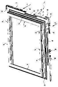
With reference to Figure 1, the number 10 designates a door
or window frame according to the present invention. The door or
window frame 10 comprises a quadrangular frame 12 formed by four
section bars 14 preferably constituted of aluminium or alloys
thereof. Each of the section bars 14 has an outer side provided
with a longitudinal groove 16.
With reference to Figures 2 and 3, the frame 12 has two
front faces designated respectively by the numbers 18 and 20.
The section bars 14 have respective front bearing edges 22
aligned to the first face 18 of the frame 12 and projecting
outwards beyond the respective groove 16. The front bearing
edges 22 have respective grooves 24 able to receive a front
sealing gasket (not shown) which in the closed position of the
window or door frame is pressed against a front surface of the
fixed frame of the door or window.
CA 02590973 2007-06-06
- 5 -
With reference for example to Figures 2 and 4, the
longitudinal groove 16 of each section bar 14 comprises a base
26, two lateral walls 28 and two longitudinal edges 30 oriented
towards each other. The two longitudinal ends of the edges 30
facing each other define the outer opening of the longitudinal
groove 16. The longitudinal edges 30 define an undercut
engagement area at each lateral wall 28 of the groove 16. A
first undercut engagement area 32 is adjacent to the first face
18 of the frame 12 and a second undercut engagement area 34 is
adjacent to the second face 20 of the frame 12.
Each undercut engagement area 32, 34 has substantially "C"
shape and is defined between the inner surfaces of the edge 30,
of the lateral wall 28 and by the lateral portion of the base
26. The shape of the longitudinal groove 16 is standardised and
it is used by most metallic section bars for door or window
frames.
With reference to Figure 1, the window or door frame 10 is
provided with a drive assembly globally designated by the number
36. The drive assembly 36 comprises a plurality of actuating
members 38, 40, 42, 46 49 and a plurality of transmission rods
48, 50 that operatively connect adjacent actuating members to
each other. The drive assembly 36 shown in Figure 1 is that of a
door or window frame with wing and swivel opening and it
comprises a vertical fulcrum 38, an angled transmission 40, a
scissors arm 42 a cremone bolt coupling and a cursor 49.
According to the present invention, each actuating member
and each transmission rod is provided with a single integral
tenon for engagement with the respective groove 16, so that all
the components of the drive assembly 36 can be mounted frontally
in the respective grooves. The tenons of the actuating members
and of the transmission rods all engage the undercut engagement
area 32 of the respective groove 16 adjacent to the first wall
18 of the frame 12, i.e. the wall provided with front bearing
CA 02590973 2007-06-06
- 6 -
edge 22.
Figures 2 to 11 schematically show some details and the
manners of mounting of some actuating members 40, 42, 49
comprising the drive assembly 36.
With reference to Figures 2 through 5, the actuating member
49 (cursor) has a single tenon 52 obtained in integral form with
the body of the actuating member 49 and engaging the first
undercut engagement area 32 of the groove 16. The actuating
member 49 is mounted by positioning the tenon 52 into the first
undercut engagement area 32 as shown in Figures 2 and 4 and then
making the engagement member 49 oscillate towards the interior
of the groove 16 obtaining the frontal insertion of the
actuating member 49 into the groove 16 as shown in Figures 3 and
5. On the opposite side of the tenon 52, the actuating member 38
is provided with a bearing longitudinal edge 54 that bears on
the outer side of the edge 30 situated at the second undercut
engagement area 34.
The actuating member 49 is fastened to the transmission rod
50 by means of a screw 56. The manner in which each actuating
member 38, 40, 42, 46 and 49 is fastened to the respective
transmission rods 48, 50 is described in detail in a
contemporaneous patent application by the same Applicant.
Figures 6 through 9 show the way in which the frontal
mounting of the angled transmission 40 is carried out. In this
case, too, the angled transmission 40 is provided with a single
integral tenon 52 that engages the first undercut engagement
area 52 of the longitudinal groove 16. The mounting operation is
carried out by frontally inserting the angled transmission 40
into the groove 16 as indicated in Figures 6 and 8 and then
making the angled transmission 40 oscillate towards the interior
of the groove 16 until it reaches the position shown in Figures
7 and 9. On the opposite side of the tenon 52 there is a bearing
edge 54 that bears on the outer side of the edge 30 situated at
CA 02590973 2007-06-06
- 7 -
the second undercut engagement area 34. The angled transmission
40 can also be provided with a recessing tooth 58 that engages
in snap-in fashion the edge 30 during the frontal insertion into
the groove 16. The recessing tooth 58 is thrust elastically
outwards and it has the purpose of holding the angled
transmission 40 inside the groove 16 during the assembly.
Similar retaining teeth can also be provided on other actuating
members of the assembly 36.
With reference to Figures 10 and 11, the scissors arm 42 is
also mounted in the manner described previously. Figures 10 and
11 show the scissors arm 42 at the end of the mounting in the
groove 16. The insertion takes place frontally, positioning the
single integral tenon 52 in engagement with the first undercut
engagement portion 32 and then making the scissors arm 42
oscillate towards the interior of the groove 16.
The fact that all the actuating members and all the
transmission rods are provided with a single tenon for
connection to the section bars 14 could cause instability
problems due to pressures on the door or window frame. However,
said problems are solved thanks to the fact that all the
actuating members engage the undercut engagement area 32 of the
groove 16 that is oriented towards the face 18 of the frame 12
provided with the front bearing edge 22. In the case of inward
opening door and window frames, the face 18 is the inner face of
the door or window frame whilst in the case of outward opening
door and window frames, the face 18 is the outer face of the
door or window frame.
The fact that all the tenons of the drive assembly 36
engage the inner portion of the groove 16 in the case of inward
opening door and window frames and the outer portion of the
groove 16 in the case of outward opening door and window frames
determines a complete stability, even without a tenon with
structural function on the opposite side of the groove 16. It
CA 02590973 2007-06-06
- 8 -
can be demonstrated that the connection between the actuating
members and the section bars 14 is perfectly stable in the case
of thrusts directed from the outside inwards, in the case of
inwardly opening door and window frames, or under the action of
thrusts directed from the inside outwards, in the case of
outwardly opening door and window frames.
The fact that all the tenons of the drive assembly 36
engage the same side of the groove 16 enables to carry out the
frontal mounting of the actuating members and of the
transmission rods without upsetting the frame 12, i.e. keeping
the frame 12 with the face 18 bearing on a horizontal plane
during the entire assembly operation.