Language selection

Search

Patent 2591109 Summary

Third-party information liability

Some of the information on this Web page has been provided by external sources. The Government of Canada is not responsible for the accuracy, reliability or currency of the information supplied by external sources. Users wishing to rely upon this information should consult directly with the source of the information. Content provided by external sources is not subject to official languages, privacy and accessibility requirements.

Claims and Abstract availability

Any discrepancies in the text and image of the Claims and Abstract are due to differing posting times. Text of the Claims and Abstract are posted:

  • At the time the application is open to public inspection;
  • At the time of issue of the patent (grant).
(12) Patent Application: (11) CA 2591109
(54) English Title: SILICONE BAKING PAN
(54) French Title: PLATEAU DE CUISSON AU FOUR DE SILICONE
Status: Deemed Abandoned and Beyond the Period of Reinstatement - Pending Response to Notice of Disregarded Communication
Bibliographic Data
(51) International Patent Classification (IPC):
  • A21B 3/13 (2006.01)
(72) Inventors :
  • KAPOSI, SASCHA (United States of America)
(73) Owners :
  • PROGRESSIVE INTERNATIONAL CORP.
(71) Applicants :
  • PROGRESSIVE INTERNATIONAL CORP. (United States of America)
(74) Agent: SMART & BIGGAR LP
(74) Associate agent:
(45) Issued:
(22) Filed Date: 2007-06-08
(41) Open to Public Inspection: 2007-12-09
Examination requested: 2010-06-01
Availability of licence: N/A
Dedicated to the Public: N/A
(25) Language of filing: English

Patent Cooperation Treaty (PCT): No

(30) Application Priority Data:
Application No. Country/Territory Date
60/804,386 (United States of America) 2006-06-09

Abstracts

English Abstract


A mold is integrally formed from a flexible material that is suitable for
baking or
molding food products, such as food grade silicone. In one example, the mold
includes a rim
at the top and a wall extending between the rim and a base at the bottom. The
wall is
sufficiently thick that the pan can support its own weight while holding a
food item. The
mold may include an interior or exterior relief pattern that is imparted onto
the food item. In
some forms, an upper portion of the mold is relatively smooth and more
flexible than a lower
portion having a relief pattern. An internal U-shaped stiffening element helps
to prevent the
mold from collapsing and improves handling of the mold.


Claims

Note: Claims are shown in the official language in which they were submitted.
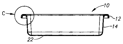

I claim:
1. A mold for preparing a food item, comprising:
a base;
a rim;
a peripheral wall extending upward from the base to the rim and defining an
interior space, the peripheral wall and base being integrally formed from a
flexible food-grade material; and
a U-shaped stiffening element secured to the mold at the rim, the stiffening
element being encased within the flexible material forming the mold.
2. The mold of claim 1, wherein the U-shaped stiffening element further
comprises a
first vertical wall and a second vertical wall, the first vertical wall being
longer than the
second vertical wall.
3. The mold of claim 2, wherein the first vertical wall defines an exterior
peripheral
edge of the rim and the second wall defines an interior peripheral edge of the
rim.
4. The mold of claim 1, wherein the peripheral wall further comprises an
interior
surface, an exterior surface, an upper portion and a lower portion, the upper
portion being
relatively smooth on the interior surface and the exterior surface, the lower
portion having a
raised pattern on the interior surface, whereby the raised pattern is imparted
onto a food item
being placed within the mold.
5. The mold of claim 4, further comprising a shelf between the upper portion
and the
lower portion of the peripheral wall.
-6-

6. The mold of claim 4, wherein the peripheral wall defines a length from the
base to
the rim, and further wherein the upper portion of the peripheral wall
comprises about one
third of the overall length.
7. The mold of claim 4, wherein the upper portion is relatively more flexible
than the
lower portion.
8. The mold of claim 1, wherein the peripheral wall is formed from silicone.
9. A mold for preparing a food item, comprising:
a rim defining a perimeter of the mold;
a first cavity for molding the food item, the first cavity having a base and a
peripheral wall extending upward from the base and defining an interior
space, the peripheral wall and base being integrally formed from a flexible
food-grade material; and
a U-shaped stiffening element secured to the mold at the rim, the stiffening
element being encased within the flexible material forming the mold.
10. The mold of claim 9, further comprising at least on additional cavity for
molding
the food item, the at least one additional cavity having a base and a
peripheral wall extending
upward from the base and defining an interior space, the peripheral wall and
base being
integrally formed from a flexible food-grade material.
11. The mold of claim 9, wherein the U-shaped stiffening element further
comprises a
first vertical wall and a second vertical wall, the first vertical wall being
longer than the
second vertical wall.
12. The mold of claim 9, wherein the mold is formed from silicone.
-7-

Description

Note: Descriptions are shown in the official language in which they were submitted.


CA 02591109 2007-06-08
SILICONE BAKING PAN
FIELD OF THE INVENTION
[0001) This invention relates generally to cooking pans and, more
particularly, to
pans used for baking.
BACKGROUND OF THE INVENTION
[0002] Removing a cake from a cake pan has always been a delicate operation.
Hours of work can be destroyed when the cake fails to separate from the pan
and breaks
apart. The same is true for muffins, breads, and other baked goods. Silicone
has recently
been used for baking pans, allowing the pan to be inverted to remove the food
item from the
pan. However, the walls of such pans are typically thin in order to permit
heat transfer and to
-1-

CA 02591109 2007-06-08
enable inversion. As a result, filling the pans, moving the pans to the oven,
and removing the
cake must be done very carefully to avoid inadvertent flexing that may cause
the batter to
spill or the cake to break apart or become deformed. The same issues also
apply to other
molded food items such as muffms, gelatins, and others.
[0003] In addition to the foregoing problems, existing silicone molds are
typically
unstable because the silicone is inherently flexible. The molds have
difficulty resting on a
surface and may tend to collapse under their own weight or under the weight of
the mold
when filled.
BRIEF DESCRIPTION OF THE DRAWINGS
[0004] Preferred and alternative embodiments of the present invention are
described in detail below with reference to the following drawings.
[0005] FIGURE 1 is a perspective view of a cake pan in accordance with an
embodiment of the present invention;
[0006] FIGURE 2 is a top view of a cake pan, in accordance with an embodiment
of the present invention;
[0007] FIGURE 3 is a side cross-sectional view of the cake pan of FIGURE 1,
taken along line A-A in FIGURE 1;
[0008] FIGURE 4 is a close-up view of detail C indicated in FIGURE 3;
[0009] FIGURE 5 is a top view of a cupcake pan, in accordance with an
embodiment of the present invention; and
[0010] FIGURE 6 is a side view of the cupcake pan of FIGURE 5.
-2-

CA 02591109 2007-06-08
DETAILED DESCRIPTION OF THE PREFERRED EMBODIMENT
[00111 Referring to FIGURES 1-3, a pan 10 is integrally formed from a flexible
material that is suitable for baking or molding food products. In the
preferred embodiment,
the pan is formed from food grade silicone. The pan includes a rim 12 at the
top and a
wall 14 extending between the rim and a base 22 at the bottom. The wall 14 is
sufficiently
thick that the pan can support its own weight.
[0012] In the example shown, the wall 14 includes an upper portion more
closely
adjacent the rim 12 and a lower portion relatively adjacent the base 22. In
some
embodiments, the upper portion of the wall may be relatively thicker than the
lower portion
of the wall. In use, the wall 14 is more prone to bending along the lower
portion than the
upper portion. This distinction in flexibility allows the mold to more readily
become
inverted than would otherwise be the case if the entirety of the mold included
a pattern as
with the lower portion of the mold.
100131 The rim 12 includes a stiffening element that is preferably a metal
ring 24
having a U-shaped cross section, as best seen in FIGURE 4. As shown, it may
more
accurately be described as an inverted J-shape, but the term "U-shape" will be
used within
this description to generically include such curved shapes regardless of
whether each vertical
side of the U is of equal height. The U-shape provides stiffness in multiple
directions while
being light-weight. In the example of the invention as shown and noted above,
one of the
legs of the U-shape is longer than the other. The upper portion of the wall 14
terminates in
one leg of the U-shaped stiffening ring 24. In addition, as shown, the
stiffening ring is
surrounded by the integrally formed silicone material of the mold.
-3-

CA 02591109 2007-06-08
[0014] When a baked good such as cake is prepared using the pan 10, a cook may
turn the pan over and press on the bottom of the wall 14 or the base of the
pan in order to
invert the pan 10 and remove a cake or other molded item. As noted above, the
wall 14 may
tend to bend or flex readily along the base and the lower portion of the wall.
In this manner,
the lower portion can be pushed downwardly to apply a force across the top of
the cake and
separate the cake from the pan. The cook may then lift up on the rim 12 to
release the cake
from the pan.
[0015] In the form as shown in Figures 1-3, the mold may be generally smooth,
both inside and out. Alternatively, the mold may include a pattern of curves,
circles, or other
designs in a relief pattern that appears on both the internal and external
sides of the mold.
This pattern imparts a corresponding pattern on the cake or other food item
being prepared
with the mold.
[0016] In another example of the invention, the molded pan is in the form of a
plurality of muffin cups. Referring to FIGURES 5 and 6, several cups 26 may be
formed and
extending downwardly from a substantially planar portion 28. A peripheral
stiffening ring is
provided at the perimeter of the muffin pan. In the illustrated embodiment,
the metal ring has
an inverted U-shaped cross section with the planar portion 28 of the pan being
generally
coplanar with the top of the metal ring (or the base of the U). Though not
illustrated in
FIGURES 5 and 6, the stiffening ring is substantially the same as that
depicted in the cross-
sectional views of FIGURES 3 and 4. The embodiment of FIGURES 5 and 6 is
advantageous
inasmuch as each individual cup 26 does not need to be supported by the cook's
hand when
moving the filled pan.
-4-

CA 02591109 2007-06-08
[00171 In the example shown, the muffin cups are each formed in the shape of
an
aesthetically pleasing design, such as flowers. In a preferred form, the pan
includes twelve
muffin cups, with four of each of three different floral designs. Although not
shown in the
example of Figures 5 and 6, all or some of the muffin cups may also include a
base such as
that described with respect to the cake pan of Figure 1.
[0018] While the preferred embodiment of the invention has been illustrated
and
described, as noted above, many changes can be made without departing from the
spirit and
scope of the invention. Accordingly, the scope of the invention is not limited
by the
disclosure of the preferred embodiment. Instead, the invention should be
determined entirely
by reference to the claims that follow.
-5-

Representative Drawing
A single figure which represents the drawing illustrating the invention.
Administrative Status

2024-08-01:As part of the Next Generation Patents (NGP) transition, the Canadian Patents Database (CPD) now contains a more detailed Event History, which replicates the Event Log of our new back-office solution.

Please note that "Inactive:" events refers to events no longer in use in our new back-office solution.

For a clearer understanding of the status of the application/patent presented on this page, the site Disclaimer , as well as the definitions for Patent , Event History , Maintenance Fee  and Payment History  should be consulted.

Event History

Description Date
Inactive: IPC expired 2016-01-01
Application Not Reinstated by Deadline 2014-04-15
Inactive: Dead - No reply to s.30(2) Rules requisition 2014-04-15
Deemed Abandoned - Failure to Respond to Maintenance Fee Notice 2013-06-10
Inactive: Abandoned - No reply to s.30(2) Rules requisition 2013-04-15
Inactive: S.30(2) Rules - Examiner requisition 2012-10-15
Amendment Received - Voluntary Amendment 2012-05-18
Inactive: S.30(2) Rules - Examiner requisition 2011-11-21
Amendment Received - Voluntary Amendment 2010-11-29
Letter Sent 2010-06-15
Request for Examination Requirements Determined Compliant 2010-06-01
Request for Examination Received 2010-06-01
All Requirements for Examination Determined Compliant 2010-06-01
Inactive: Cover page published 2007-12-09
Application Published (Open to Public Inspection) 2007-12-09
Inactive: IPC assigned 2007-08-07
Inactive: First IPC assigned 2007-08-07
Inactive: IPC assigned 2007-08-07
Inactive: Filing certificate - No RFE (English) 2007-07-18
Filing Requirements Determined Compliant 2007-07-18
Application Received - Regular National 2007-07-11

Abandonment History

Abandonment Date Reason Reinstatement Date
2013-06-10

Maintenance Fee

The last payment was received on 2012-04-16

Note : If the full payment has not been received on or before the date indicated, a further fee may be required which may be one of the following

  • the reinstatement fee;
  • the late payment fee; or
  • additional fee to reverse deemed expiry.

Please refer to the CIPO Patent Fees web page to see all current fee amounts.

Fee History

Fee Type Anniversary Year Due Date Paid Date
Application fee - standard 2007-06-08
MF (application, 2nd anniv.) - standard 02 2009-06-08 2009-03-09
MF (application, 3rd anniv.) - standard 03 2010-06-08 2010-05-26
Request for examination - standard 2010-06-01
MF (application, 4th anniv.) - standard 04 2011-06-08 2011-03-16
MF (application, 5th anniv.) - standard 05 2012-06-08 2012-04-16
Owners on Record

Note: Records showing the ownership history in alphabetical order.

Current Owners on Record
PROGRESSIVE INTERNATIONAL CORP.
Past Owners on Record
SASCHA KAPOSI
Past Owners that do not appear in the "Owners on Record" listing will appear in other documentation within the application.
Documents

To view selected files, please enter reCAPTCHA code :


To view images, click a link in the Document Description column. To download the documents, select one or more checkboxes in the first column and then click the "Download Selected in PDF format (Zip Archive)" or the "Download Selected as Single PDF" button.

List of published and non-published patent-specific documents on the CPD .

If you have any difficulty accessing content, you can call the Client Service Centre at 1-866-997-1936 or send them an e-mail at CIPO Client Service Centre.


Document
Description 
Date
(yyyy-mm-dd) 
Number of pages   Size of Image (KB) 
Description 2007-06-08 5 139
Abstract 2007-06-08 1 16
Claims 2007-06-08 2 60
Drawings 2007-06-08 2 44
Representative drawing 2007-11-13 1 3
Cover Page 2007-11-30 1 32
Description 2012-05-18 6 166
Claims 2012-05-18 2 61
Filing Certificate (English) 2007-07-18 1 158
Reminder of maintenance fee due 2009-02-10 1 112
Acknowledgement of Request for Examination 2010-06-15 1 177
Courtesy - Abandonment Letter (R30(2)) 2013-06-10 1 165
Courtesy - Abandonment Letter (Maintenance Fee) 2013-08-05 1 172
Fees 2010-05-26 1 36
Fees 2011-03-16 1 35
Fees 2012-04-16 1 67