Language selection

Search

Patent 2591395 Summary

Third-party information liability

Some of the information on this Web page has been provided by external sources. The Government of Canada is not responsible for the accuracy, reliability or currency of the information supplied by external sources. Users wishing to rely upon this information should consult directly with the source of the information. Content provided by external sources is not subject to official languages, privacy and accessibility requirements.

Claims and Abstract availability

Any discrepancies in the text and image of the Claims and Abstract are due to differing posting times. Text of the Claims and Abstract are posted:

  • At the time the application is open to public inspection;
  • At the time of issue of the patent (grant).
(12) Patent Application: (11) CA 2591395
(54) English Title: METHOD OF AUTOMATED OIL WELL PUMP CONTROL AND AN AUTOMATED WELL PUMP CONTROL SYSTEM
(54) French Title: METHODE DE COMMANDE AUTOMATIQUE DE PUITS DE PETROLE ET SYSTEME DE COMMANDE AUTOMATIQUE DE POMPE DE PUITS
Status: Deemed Abandoned and Beyond the Period of Reinstatement - Pending Response to Notice of Disregarded Communication
Bibliographic Data
(51) International Patent Classification (IPC):
  • E21B 43/12 (2006.01)
  • F04B 49/06 (2006.01)
  • F04B 49/20 (2006.01)
  • F04B 49/22 (2006.01)
  • F04C 14/08 (2006.01)
  • F04C 14/24 (2006.01)
  • F04D 15/00 (2006.01)
(72) Inventors :
  • ZAROWNY, CAMERON (Canada)
  • MUIR, WAYNE (Canada)
  • YOUNG, WENDELL (Canada)
(73) Owners :
  • NORALTA TECHNOLOGIES INC.
(71) Applicants :
  • NORALTA TECHNOLOGIES INC. (Canada)
(74) Agent: DOUGLAS B. THOMPSONTHOMPSON, DOUGLAS B.
(74) Associate agent:
(45) Issued:
(22) Filed Date: 2007-06-01
(41) Open to Public Inspection: 2008-12-01
Availability of licence: N/A
Dedicated to the Public: N/A
(25) Language of filing: English

Patent Cooperation Treaty (PCT): No

(30) Application Priority Data: None

Abstracts

English Abstract


A method of automated oil well pump control. A first step involves preventing
flow in
a flow line carrying produced fluids from an oil well while continuing to
operate a pump
pumping produced fluids from the oil well. A second step involves monitoring
pressure in the
flow line between the pump and the valve over a pre-selected time interval to
establish a
pressure profile. A third step involves speeding up the pump and monitoring
any change in
the pressure profile. When the pressure profile is characterized by a rise in
pressure indicating
that the pump speed has not yet exceeded well production, further increasing
the speed of the
pump. When the pressure profile shows an intermittent rise in pressure
indicating that the
pump speed is exceeding well production, deceasing the speed of the pump.


Claims

Note: Claims are shown in the official language in which they were submitted.

4
What is Claimed is:
1. A method of automated oil well pump control, comprising:
preventing flow in a flow line carrying produced fluids from an oil well while
continuing to operate a pump pumping produced fluids from the oil well;
monitoring pressure in the flow line between the pump and the valve over a pre-
selected time interval to establish a pressure profile;
speeding up the pump and monitoring any change in the pressure profile, when
the
pressure profile is characterized by a rise in pressure indicating that the
pump speed has not
yet exceeded well production further increasing the speed of the pump and when
the pressure
profile shows an intermittent rise in pressure indicating that the pump speed
is exceeding well
production, deceasing the speed of the pump.
2. The method of claim 1, wherein preventing flow in a flow line comprises
closing a valve.
3. An automated oil well pump control system, comprising:
an oil well having a pump;
a flow line carrying produced fluids from the oil well;
means of controlling the flow of produced fluids through the flow line;
a pressure sensor on the flow line between the pump and the control valve;
a controller controlling the speed of the pump, controlling the opening and
closing of
the control valve and receiving pressure readings from the pressure sensor,
the controller
having a control strategy in which the controller closes the control valve for
a pre-selected
time interval, monitors a resulting rise in pressure in the flow line over the
pre-selected time
interval, and speeds up or slows down the pump based upon a pressure profile,
when the
pressure profile is characterized by a rise in pressure indicating that the
pump speed has not
yet exceeded well production further increasing the speed of the pump and when
the pressure
profile shows an intermittent rise in pressure indicating that the pump speed
is exceeding well
production, deceasing the speed of the pump.
4. The automated oil well pump control system of Claim 3, wherein the pump is
a rotary

5
pump and pump speed in measured in rotations per minute (rpm).
5. The automated oil well pump control system of Claim 3, wherein the means of
controlling
the flow of produced fluids is an automated control valve.

Description

Note: Descriptions are shown in the official language in which they were submitted.


CA 02591395 2007-06-01
1
TITLE:
Method Of Automated Oil Well Pump Control And An Automated Well Pump
Control System
FIELD
The present invention relates to a method of automated oil well pump control
that
speeds up and slows down a pump positioned in an oil well and, an automated
well pump
control system in accordance with the teachings of the method.
BACKGROUND
Various automated control systems are known for matching pump rotations per
minute with the rate that fluids flow into a well bore of an oil well.
Canadian Patent 2,510,101
(Zarowny et al) describes a control system that is based upon the rate of rise
of produced
fluids in a production tank. This control system cannot be used, when several
wells are
producing fluids that accumulate in a single production tank, including wells
that are flow
lined.
SUMMARY
There is provided a method of automated oil well pump control. A first step
involves
preventing flow in a flow line carrying produced fluids from an oil well while
continuing to
operate a pump pumping produced fluids from the oil well. A second step
involves
monitoring pressure in the flow line between the pump and the valve over a pre-
selected time
interval to establish a pressure profile. A third step involves speeding up
the pump and
monitoring any change in the pressure profile. When the pressure profile shows
a rise in
pressure indicating that the pump speed has not yet exceeded well production,
further
increasing the speed of the pump. When the pressure profile shows an
intermittent rise in
pressure indicating that the pump speed is exceeding well production,
deceasing the speed of
the pump.
3 0 BRIEF DESCRIPTION OF THE DRAWINGS
These and other features will become more apparent from the following
description in
which reference is made to the appended drawings, the drawings are for the
purpose of

CA 02591395 2007-06-01
2
illustration only and are not intended to in any way limit the scope of the
invention to the
particular embodiment or embodiments shown, wherein:
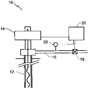
THE FIGURE is a schematic view of an automated oil well pump control.
DETAILED DESCRIPTION
An automated oil well pump control, generally indicated by reference numeral
10,
will now be described with reference to THE FIGURE.
Structure and Relationship of Parts:
Referring to FIG. 1, automated oil well pump control 10 includes an oil well
12
having a pump 14 and a flow line 16 that carries produced fluids from oil well
12. While a
screw pump has been illustrated, it will be understood that other suitable
types of pumps
could also be used. There is also a means of controlling the flow of produced
fluids, such as
an automated control valve 18 on flow line 16 as depicted, with a pressure
sensor 20
positioned on flow line 16 between pump 14 and control valve 18. A controller
22 is used to
control the speed of pump 14, control the opening and closing of control valve
18 and receive
pressure readings from pressure sensor 20. Controller 22 has a control
strategy in which
controller 22 closes control valve 18 for a pre-selected time interval,
monitors a resulting rise
in pressure in flow line 16 over the pre-selected time interval, and speeds up
or slows down
pump 14 based upon a pressure profile, as will hereinafter be further
described.
Operation:
Referring to THE FIGURE, valve 18 is first closed on flow line 16, which is
carrying
produced fluids from oil well 12. Pump 14 continues to operate to pump
produced fluids
from oil well 12. Using pressure sensor 20, the pressure in flow line 16
between pump 14 and
valve 18 is monitored over a pre-selected time interval to establish a
pressure profile. The
speed of pump 14 is then increased, and any change in the pressure profile is
monitored. A
continuous rise in pressure shown by the pressure profile indicates that the
speed of pump 14
has not yet exceeded well production, and the speed of pump 14 may be
increased further.
An intennittent rise in pressure shown by the pressure profile indicates that
the pump speed is
exceeding well production, and thus the speed of pump 14 ought to be
decreased.

CA 02591395 2007-06-01
3
A pressure profile showing a continuous rise in pressure looks as follows:
Time
A pressure profile showing an intermittent rise in pressure looks as follows:
3y
rrm
This method was developed for use with a pump that rotates, so that the
rotations per
minute (rpm) of the pump are increased or decreased in accordance with the
control strategy.
It will also work with other types of pumping apparatus.
In this patent document, the word "comprising" is used in its non-limiting
sense to
mean that items following the word are included, but items not specifically
mentioned are not
excluded. A reference to an element by the indefinite article "a" does not
exclude the
possibility that more than one of the element is present, unless the context
clearly requires that
there be one and only one of the elements.
It will be apparent to one skilled in the art that modifications may be made
to the
illustrated embodiments without departing from scope of the Claims.

Representative Drawing
A single figure which represents the drawing illustrating the invention.
Administrative Status

2024-08-01:As part of the Next Generation Patents (NGP) transition, the Canadian Patents Database (CPD) now contains a more detailed Event History, which replicates the Event Log of our new back-office solution.

Please note that "Inactive:" events refers to events no longer in use in our new back-office solution.

For a clearer understanding of the status of the application/patent presented on this page, the site Disclaimer , as well as the definitions for Patent , Event History , Maintenance Fee  and Payment History  should be consulted.

Event History

Description Date
Time Limit for Reversal Expired 2011-06-01
Application Not Reinstated by Deadline 2011-06-01
Extension of Time to Top-up Small Entity Fees Requirements Determined Compliant 2011-02-25
Inactive: Entity size changed 2011-02-25
Inactive: Corrective payment - Application fee 2011-02-25
Inactive: Office letter 2011-02-25
Deemed Abandoned - Failure to Respond to Maintenance Fee Notice 2010-06-01
Letter Sent 2009-08-26
Inactive: Single transfer 2009-08-10
Inactive: Correspondence - Formalities 2009-03-04
Application Published (Open to Public Inspection) 2008-12-01
Inactive: Cover page published 2008-11-30
Inactive: IPC assigned 2008-11-25
Inactive: First IPC assigned 2008-11-25
Inactive: Correspondence - Formalities 2008-06-02
Letter Sent 2008-05-16
Inactive: Single transfer 2008-04-03
Inactive: Adhoc Request Documented 2008-01-02
Appointment of Agent Request 2007-11-16
Revocation of Agent Request 2007-11-16
Application Received - Regular National 2007-07-16
Inactive: Filing certificate - No RFE (English) 2007-07-16
Small Entity Declaration Determined Compliant 2007-06-01

Abandonment History

Abandonment Date Reason Reinstatement Date
2010-06-01

Maintenance Fee

The last payment was received on 2009-04-21

Note : If the full payment has not been received on or before the date indicated, a further fee may be required which may be one of the following

  • the reinstatement fee;
  • the late payment fee; or
  • additional fee to reverse deemed expiry.

Patent fees are adjusted on the 1st of January every year. The amounts above are the current amounts if received by December 31 of the current year.
Please refer to the CIPO Patent Fees web page to see all current fee amounts.

Fee History

Fee Type Anniversary Year Due Date Paid Date
Application fee - standard 2007-06-01
Registration of a document 2008-04-03
MF (application, 2nd anniv.) - standard 02 2009-06-01 2009-04-21
Registration of a document 2009-08-10
Owners on Record

Note: Records showing the ownership history in alphabetical order.

Current Owners on Record
NORALTA TECHNOLOGIES INC.
Past Owners on Record
CAMERON ZAROWNY
WAYNE MUIR
WENDELL YOUNG
Past Owners that do not appear in the "Owners on Record" listing will appear in other documentation within the application.
Documents

To view selected files, please enter reCAPTCHA code :


To view images, click a link in the Document Description column. To download the documents, select one or more checkboxes in the first column and then click the "Download Selected in PDF format (Zip Archive)" or the "Download Selected as Single PDF" button.

List of published and non-published patent-specific documents on the CPD .

If you have any difficulty accessing content, you can call the Client Service Centre at 1-866-997-1936 or send them an e-mail at CIPO Client Service Centre.


Document
Description 
Date
(yyyy-mm-dd) 
Number of pages   Size of Image (KB) 
Description 2007-05-31 3 110
Abstract 2007-05-31 1 18
Claims 2007-05-31 2 49
Drawings 2007-05-31 1 6
Representative drawing 2008-11-04 1 4
Filing Certificate (English) 2007-07-15 1 157
Courtesy - Certificate of registration (related document(s)) 2008-05-15 1 130
Reminder of maintenance fee due 2009-02-02 1 112
Courtesy - Certificate of registration (related document(s)) 2009-08-25 1 121
Courtesy - Abandonment Letter (Maintenance Fee) 2010-07-26 1 172
Correspondence 2007-07-15 2 108
Correspondence 2007-10-08 1 30
Correspondence 2007-11-15 5 123
Correspondence 2008-05-15 1 22
Correspondence 2008-06-01 2 67
Correspondence 2009-02-02 1 39
Correspondence 2009-03-03 6 152
Correspondence 2009-08-25 1 22
Fees 2009-04-20 1 31
Correspondence 2010-07-26 1 99
Correspondence 2011-02-24 1 14
Correspondence 2011-02-24 1 22