Note: Descriptions are shown in the official language in which they were submitted.
CA 02591467 2007-06-13
TRANSFER DEVICE FOR FLUIDS
FIELD OF THE INVENTION
The present invention relates to a transfer device and more particularly,
relates to a
transfer device suitable for transferring fluid contents from a first
cartridge to a second
container.
BACKGROUND OF THE INVENTION
In the pharmaceutical field, medicants can be packaged in a first type of
container
and need to be transferred to a second type of container. The reason could be
that the
second type of container is a specialized one which is difficult to fill on
known production
lines. A second situation can arise when it is desired to transfer a fluid
into a second
container which may contain a second drug component which is to be mixed with
the first
fluid. In this regard, reference may be had to PCT Application CA2005/001839,
the
teachings of which are hereby incorporated by reference.
SUMMARY OF THE INVENTION
It is an object of the present invention to provide a transfer device for
transferring
fluid from a cartridge or a first container to a second container in a sterile
environment. As
used herein, the term fluid includes any substance having a liquid component
thereof
including, for example, suspensions, solutions, emulsions, etc.
The transfer device also preferably includes means for ejecting the filled
container
therefrom.
BRIEF DESCRIPTION OF THE DRAWINGS
Having thus generally described the invention, reference will be made to the
accompanying drawings illustrating embodiments thereof, in which:
-1-
CA 02591467 2007-06-13
Figure 1 is a schematic side sectional view of a transfer device according to
one
embodiment of the present invention;
Figures 2A, 2B and 2C are views similar to Figure 1 illustrating the
sequential
operation for the venting of the container to be filled;
Figure 3 is a similar view showing the indexing of the cap;
Figures 4A and 4B are similar views illustrating transfer of the fluid from
the
cartridge to the container.
Figure 5 is an exploded view of a further embodiment of a further embodiment
of a
transfer device according to an embodiment of the present invention;
Figure 6A is a perspective view of the transfer device of Figure 5
illustrating the
initial movement and venting of the container;
Figure 6B is a first side sectional view thereof;
Figure 6C is a second side elevational view thereof;
Figure 7A is a perspective view showing puncturing of the container;
Figures 7B and 7C are side sectional views thereof;
Figure 8A is a perspective view showing puncturing of the cartridge;
Figures 8B and 8C are side sectional views thereof;
Figure 9A is a perspective view showing the commencement of the transfer of
the
fluid from the cartridge to the container;
Figures 9B and 9C are side sectional views thereof;
Figure l 0A is a perspective view of the transfer device following transfer of
the fluid;
Figures lOB and lOC are side sectional views thereof;
Figure 11A is a perspective view showing the ejection of the container from
the
-2-
CA 02591467 2007-06-13
transfer device; and
Figures 11B and 11C are side sectional views thereof. -
DETAILED DESCRIPTION OF THE INVENTION
Referring to the drawings in greater detail and by reference characters
thereto, there
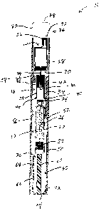
is illustrated in Figure 1 a transfer device generally designated by reference
numeral 10.
Transfer device 10 includes a conventional fluid containing cartridge 12, a
container 14 to which the fluid is to be transferred, and a shuttle 16.
Cartridge 12 has a cylindrical body 20 and may be of any suitable dimensions
though
in the illustrated embodiment, it is of an elongated configuration with a
plunger 22 being
located at one end thereof. At the other end, there is provided a pierceable
cap 24 while the
cylindrical body 20 contains a fluid 26 to be transferred to container 14.
Container 14, to which the fluid is to be transferred, has an outer wall 28
defining the
container with a pierceable plunger 30 located at one end thereof. A proboscis
32 is located
at the other end.
Shuttle 16 includes a main body portion 36 with legs 38 extending from one end
thereof. In the illustrated embodiment, there are provided two such legs 38.
Each leg 38 has
at an end thereof a flange 40 extending diagonally outwardly.
Extending through main body 36 is a cannula which has a first piercing tip 44
located
at one end thereof and a second piercing tip 46 located at the other end
thereof.
Transfer device 10 also includes an outer housing 50. On the interior wall of
housing 50 there is provided a first shoulder 52 which has a substantial
length for reasons
which will be discussed hereinbelow. A second shorter shoulder 54 is provided
on the other
side thereof. It will also be seen that outer housing 50 has an inwardly
extending portion 56
-3-
CA 02591467 2007-06-13
located on an inner wall thereof, again for reasons which will be discussed
hereinbelow.
A pusher mechanism generally designated by reference numeral 60 includes a
centrally located plunger rod 62 and an end cap 64 at one end thereof. A
second outer
pusher element 66 extends parallel to and spaced from plunger rod 62 and
terminates in an
inwardly extending flange 70. It will be noted that outer pusher element 66
has a
protrusion 68 extending outwardly therefrom. End cap 64 also has a second end
flange 72.
Transfer device 10 also includes a cap 76 having a top wall 78 and a side wall
80 and
which cap 76 extends over the end of housing 50. A stopper 82 extends inwardly
from side
wall 80.
In use, and as shown in Figure 1, cartridge 12 is placed interiorly of housing
50.
Subsequently, and as shown in Figures 2A, 2B and 2C, container 14 is vented.
To
accomplish the venting, pusher mechanism 60 is continually pushed as indicated
by
arrows 84. The initial pushing causes end flange 70 to engage the end of
cylindrical body 20
and exert pressure thereon. Cartridge 12 is then urged into a position wherein
flanges 40 on
legs 38 of shuttle 16 engage a shoulder portion of cartridge 12. A flange 40
also engages
shoulder 52 to prevent outer movement thereof. This causes shuttle 16 to move
to a position
wherein first piercing tip 44 of cannula 42 pierces plunger 30 of container
14. A subsequent
movement, as indicated by arrow 84 and as shown in Figure 2A, causes plunger
30 to move
towards its upper end. Air from container 14 is vented through cannula 42.
As may be seen in Figures 2B and 2C, when plunger 30 is at the upper end of
container 14, further movement is not possible. However, at the same time,
legs 38 and
flanges 40 have passed by shoulders 52 and 54 thereby permitting outward
movement of the
legs 38. Second piercing tip 46 will then pierce the pierceable cap 24 on
cartridge 12 as
-4-
CA 02591467 2007-06-13
seen in Figure 2C.
Subsequently, cap 76 is rotated as shown in Figure 3 by arrow 86. Stopper 82
is then
no longer engaging proboscis 32 and this permits the upward movement of
container 14,
shuttle 16, cartridge 12 and pusher mechanism 60 to the position shown in
Figure 4A. At
this point in time, protrusion 68 on outer pusher element 66 will engage
inwardly extending
protrusion 56. This will cause the outer flexing of end flange 70 such that it
will extend
outwardly of cartridge 12 and no longer be in a position to push cartridge 12
upwardly. At
this point in time, plunger rod 62 will contact plunger 22 to thereby put
pressure on fluid 34
and force the same through cannula 42 into container 14 as may be seen in
Figure 4B. As
may also be seen in Figure 4B, shoulders 52 and 54 will prevent pusher
mechanism 60 from
going past a certain point.
Subsequently, cap 76 may be removed to permit access to container 14.
It will be understood that many different configurations of cartridge 12 and
container 14 may be utilized.
Referring to the embodiment of Figures 5 to 11, a second type of transfer
device is
generally designated by reference numeral I 10.
Transfer device 110, as may be best seen in Figure 5, comprises a pusher
mechanism
generally designated by reference numeral 112, a cartridge holder generally
designated by
reference numeral 114 and a cartridge generally designated by reference
numeral 116.
There is also provided a needle assembly generally designated by reference
numeral 118, a shuttle 120, an ejector 122, a container holder 124, a
container 126 and a
cap 128.
Pusher mechanism 112 includes a plunger rod 132 secured to an end cap 134.
-5-
CA 02591467 2007-06-13
Extending parallel to plunger rod 132 from end cap 134 are a pair of legs 136
which are
spaced exteriorly of plunger rod 132. On legs 136, there are provided
interiorly extending
protrusions 138 and exteriorly extending protrusions 140.
Cartridge holder 114 is designed to receive a standard fluid containing
medical
cartridge (in this particular case a 3 ml cartridge) and comprises a side wall
144 with a
base 146 being spaced inwardly from the bottom of side wall 144. At its upper
end,
legs 148 are provided with an enlarged portion which terminates in a sloped
ramp segment
152 for reasons which will become apparent hereinbelow.
Cartridge 116, as aforementioned, is a standard cartridge such as used in the
pharmaceutical industry and comprises a cylindrical body 156 with a plunger
158 located at
the bottom thereof. At the upper end, cartridge 116 is provided with a
pierceable cap 160.
Interiorly of cylindrical body 158, there is a fluid 162 which is to be
transferred to
container 126. Again, fluid 162 may be any conventional fluid such as a
liquid, suspension,
solution, emulsion, etc.
Needle assembly 118 includes a needle hub 164, an upper needle sheath 166, and
a
lower needle sheath 168. Needle hub 164 retains a cannula having an upper
piercing tip 172
and a lower piercing tip 174.
Shuttle 120 has a lower body portion 178 which has an inverted U-shaped slot
180
formed on opposite sides of lower body portion 178 for reasons which will be
discussed
hereinbelow. Lower body portion 178 is somewhat oval in cross-section and
includes a pair
of side walls 182. Shuttle 120 has an interior transverse wall 184. Interior
transverse wall 184 serves to
mount levers 186 on either side of the shuttle 120. Each lever 186 has an
upper inner
-6-
CA 02591467 2007-06-13
protrusion 189 having a sloped ramp segment 191 while having a lower outwardly
extending
protrusion 190 also with a sloped ramp segment 192. An upper body portion 194
of
shuttle 120 has a slot 196 formed therein and as well, at the upper end,
includes inwardly
extending protrusions 198.
Ejector 122 comprises a coil spring 200.
Container holder 124 has a lower cylindrical body portion 204 which has a
flange 206
at the upper end thereof extending outwardly. A base 208 is located at the
bottom of lower
body portion 204. Lower body portion 204 is defined by a side wa11210.
Extending upwardly from lower body portion 204 is an upper wall segment 212
which, at its upper end, has a horizontal wall segment 214 and an upper wall
segment 216.
Tongues 218 extend inwardly from upper wall segment 216.
Container 126 has a main body portion 222 and a proboscis 224 extending from
an
upper wall thereof. Proboscis 224, on at least one side thereof, is formed of
a resealable
material which can be pierced by a needle and once the needle is withdrawn,
seal itself.
Such materials are well known in the pharmaceutical industry. A pierceable
resealable
sea1223 closes the bottom of container 126.
Cap 128, which is best seen in Figures 6A to 6C, includes a side wa11228 and a
top
wa11230. There is an opening in side wa11228 and an interior structure
including grooves
(not shown) to permit movement along tongues 218 of container holder 124.
Mounted
interiorly of a cap 128 is a venting needle 226 which is designed to pierce
proboscis 224 to
permit venting through needle 232. A hydrophobic filter 234 is provided to
permit air to
pass therethrough while preventing the passage of any liquid.
Referring initially to Figures 6A to 6C, as indicated by arrow 236, cap 128 is
slid into
-7-
CA 02591467 2007-06-13
a position such that needle 226 will pierce proboscis 224 to permit venting of
the interior of
container 126.
Subsequently, as indicated by arrow 238, pressure is applied to legs 136
followed by
upward movement of pusher mechanism 112 as indicated by arrow 240 in Figure
7A.
This upward movement will cause cartridge holder 114 to move upwardly. In so
doing,
and as may be seen in Figures 7B, 7C, 8B and 8C, enlarged portion 150 of legs
148, due
to the sloped ramp segment 152, moves inwardly from a recess 195 in lower body
portion 178 as indicated by arrows 242. Thus, the wall of shuttle 120 will
flex outwardly
due to U-shaped cut 180 to permit passage of enlarged portion 150. As a
result, needle
hub 164 moves upwardly and upper piercing tip 172 of cannula 170 will pierce
seal 223 of
container 126.
Enlarged portions 150 then enter the space between the lower portion of lever
186
and a central body portion of shuttle 120. In so doing, they then exert an
outwardly
extending pressure on the lower part of lever 186 as indicated by arrows 244.
Further
movement will result in the lower piercing tip 174 entering into pierceable
cap 160 of
cartridge 116 as shown in Figures 9B and 9C.
After the piercing of pierceable cap 160, pressure on the legs 136 is released
as
indicated by arrows 246 in Figure 9A. Continued upward pressure as indicated
by
arrow 240 will then cause engagement of plunger rod 132 with plunger 158 to
exert pressure
on the fluid 162 and transfer the same through cannula 170 into the interior
of cartridge 116.
As may be seen in Figures 10A, lOB and IOC, legs 136 of pusher mechanism 112
will then engage the lower outer protrusions 190 and in particular the sloped
ramp
segment 192 to cause the lower end of lever 186 to move inwardly. This inward
movement,
-8-
CA 02591467 2007-06-13
as indicated by arrow 248 will then cause the outward movement of the upper
portion of
lever 186 as indicated by arrow 250. This movement releases the engagement of
upper inner
protrusion 188 with the flange 206 of lower body portion 204 of cartridge
holder 114.
As a result of the above, coil spring 200 exerts an upward pressure on
container
holder 124 such that when cap 128 is removed as shown in Figures 11 A, 11 B
and 11 C, the
container holder 124 is moved upwardly such that access may be had to the
container 126.
It will be understood that the above described embodiments are for purposes of
illustration only and that changes and modifications may be made thereto
without departing
from the spirit and scope of the invention.
-9-