Note: Descriptions are shown in the official language in which they were submitted.
CA 02591683 2007-03-28
WO 2006/045415 PCT/EP2005/010807
Tube made of a profile rolled metal product and method of producing the same
FIELD OF THE INVENTION
The invention relates to a tube made of a profile rolled metal product, in
particular for use in heat exchangers, a rolled metal product and a method for
producing the same. In particular, the invention is directed to a tube
including a
plurality of reinforcing structures forming longitudinal passages for
transporting fluid,
e.g. a refrigerant, between them.
BACKGROUND OF THE INVENTION =
Heat exchanges such as condensers, evaporators and the like for use in car
coolers, air conditioning systems etc. usually comprise a number of heat
exchange
tubes arranged in parallel between two headers, each tube joined at either end
to one
of the headers. Corrugated fins are disposed in an airflow clearance between
adjacent
heat exchange tubes and are brazed to the respective tubes. The heat exchanger
is
typically made of aluminium or an aluminium alloy.
In the past, flat refrigerant tubes have been manufactured by folding a
brazing
sheet clad on the outside with a brazing material layer. The refrigerant
tubes, the
headers and the fins, were then assembled and heated to the brazing
temperature at
which the clad layer melts and joins together the fins, refrigerant tubes and
headers
into a brazed assembly.
It is envisaged gases such as carbon dioxide will be used as cooling medium in
air-conditioning systems. The use of carbon dioxide will lead to an increase
in
operating temperature and pressure of the air-conditioning units. The above-
described
conventional brazed tubes might not withstand under all circumstances the
encountered operating pressures and temperatures. For the existing carbon
dioxide
based prototypes, the heat exchange tubes have therefore been made of a hollow
extrusion comprising flat upper and lower walls and a number of reinforcing
walls
connecting the upper and lower walls. A disadvantage of the extrusion
technique is
that the walls cannot be made as thin as desired. Further, an extruded tube
cannot be
clad with brazing material, so the corrugated fins must be clad in order to
allow brazing
to the heat exchange tubes, which is expensive due to the large surface area
of the
fins. In addition, a tube made of brazed sheet or plate is stronger and more
resistant
against corrosion than extruded tubes.
US-5,931,226 discloses a refrigerant tube or fluid tube for use in heat
exchangers comprising a flat tube having upper and lower walls and a plurality
of
longitudinal reinforcing walls connected between the upper and lower walls.
The
reinforcing walls consist of ridges projecting inward from the upper or lower
wall and
CONFIRMATION COPY
CA 02591683 2007-03-28
WO 2006/045415 PCT/EP2005/010807
2
are joined to the flat inner surface of the other wall. The ridges are
produced by rolling
an aluminium sheet clad with a brazing filler metal layer over at least one of
its
opposite surfaces with a roll having parallel annular grooves. Parallel
refrigerant or
fluid passages are defined between adjacent reinforcing walls. Further, the
reinforcing
walls include a plurality of communication holes for causing the parallel
refrigerant
passages to communicate with one another. In another embodiment, each
reinforcing
wall is formed by a ridge projecting from the upper wall and a ridge
protecting from the
lower wall, joined to each other at their respective top ends. The upper and
lower walls
are either produced separately or in one sheet, whereby the flat refrigerant
tube is
manufactured by folding the sheet longitudinally at its midpoint like a
hairpin.
US-5,947,365 describes a process for producing a similar flat heat exchange
tube having a plurality of reinforcing walls formed of ridges projecting from
the lower
wall. The upper and lower walls are connected by brazing the tops of the
ridges on the
lower wall to the upper wall. In order to strengthen the brazed connection
between the
reinforcing walls and the lower surface of the upper wall and to prevent the
creation of
a clearance space there between, the lower surface of the upper wall is
provided with
smaller longitudinal ridges with which the upper surfaces of the reinforcing
walls come
into contact to eliminate the clearances and thereby to insure the existence
of a
continuous brazed connection between each reinforcing wall and lower surface
of the
upper wall.
A different method of producing reinforcing walls in a flat refrigerant tube
for use
in heat exchangers is shown in US-5,186,250. The tube comprises one or more
curved
lugs integral with and protruding inwardly from an inner surface of each plane
wall, and
the curved lugs respectively have innermost tops so that the innermost tops
protruding
from one plane wall bear against the inner surface of the other plane wall or
against
the tops of the other curved lugs protruding from the opposite plane wall. The
purpose
of such protruding lugs is said to improve the pressure resistance of the tube
while
minimizing its height and thickness.
In the production of these known tubes, it is difficult to achieve a precise
alignment between the ridges on the upper and lower walls, especially in those
embodiments where two ridges protruding from opposing walls have to be joined
head-on. Further, the brazed connection between the ridges or between the top
of a
ridge and the lower surface of the opposing wall is not very strong.
CA 02591683 2012-12-18
WO 2006/045415 PCT/EP2005/010807
3
SUMMARY OF THE INVENTION
It is an object of the present invention to provide a tube made of a profile
rolled
metal product, in particular for use in heat exchangers, made of a profile
rolled metal
product, the tube comprising a first wall and a second wall forming two
opposing walls
of said tube, and a plurality of reinforcing structures connecting the first
and second
walls and forming longitudinal passages for transporting fluid between the
first and the
second wall, and having an improved strength and pressure resistance. It is
further an
object of the invention to provide a relative simple method of producing such
a profile
rolled tube.
The invention meets one or more of these objects by providing a tube made of a
profile rolled metal product according to the independent claims.
Preferred
embodiments are described and specified by this specification.
DETAILED DESCRIPTION OF THE PREFERRED EMBODIMENTS
As will be appreciated herein below, except otherwise indicated, all alloy
designations and temper designations refer to the Aluminium Association
designations
in Aluminium Standards and Data and the Registration Records, as published by
the
Aluminium Association.
A tube made of a profile rolled metal product, in particular
for use in heat exchangers includes a first wall and a second wall forming two
opposing sides of the tube, and a plurality of reinforcing structures
connecting the first
and the second walls and forming longitudinal passages for transporting fluid
(also
referred to as fluid passages) between them. Each reinforcing structure
compromises
a longitudinal ridge on the first wall projecting towards the second wall and
a
longitudinal ridge on the second wall projecting towards the first wall, the
ridges
engaging each other at theirs sides. The sideways engagement of the ridges has
one
or more of the following advantages. First, it gives a more stable and
pressure
resistant junction between the first and the second wall because the areas
joined
together may be made relatively large. Further, the joint is subjected to
shear forces
rather than traction forces when the pressure inside the tube increases. In
addition, the
positioning of the first and second walls on top of each other is facilitated
if the ridges
engage each other's sideways. Hence, the ridges might serve as a positioning
aid
directing the walls to the desired position with respect to one another.
There are several preferred embodiments of the profile geometry of the first
and
second walls. Preferably the ridges disposed on the first or second walls are
broader
at the base than at the top, though most embodiments will work with a
rectangular
CA 02591683 2007-03-28
WO 2006/045415 PCT/EP2005/010807
4
profile, or a cone-shaped profile too. At present, a trapezoidal cross-section
is most
preferred.
In a preferred embodiment, the first wall has the same profile, i.e. the same
ridge
geometry as the second wall. This has the additional advantage that the fluid
tube may
be produced by folding a single sheet.
It has been found advantageous to provide the ridges with cut-outs forming
communication holes or passages for causing adjacent fluid passages to
communicate
with one another. Thus, the ridges are not continuous over the entire length
of a tube,
but have gaps spaced from one another, forming the holes. Such holes are
believed to
cause turbulence in the refrigerant flow and thus promote the heat exchange
between
the tube walls and the refrigerant flowing through the tube.
In a particularly preferred embodiment, both walls have a profile of ridges
which
are broader at the base than at the top and spaced from one another such that
a
groove is formed between two neighbouring ridges, wherein the two sides of a
ridge
engage the two sides of a groove in the opposing wall, thereby forming a
longitudinal
passage in the groove. This embodiment has particularly high strength, because
each
ridge may be connected to another ridge on either side. When assembling the
two
walls, the ridges on either wall will interdigitate and thereby exactly fit
into one another.
Therefore, this design is particularly easy to assemble. The same applies for
the cone-
shaped profiles mutatis mutandis.
According to the second embodiment, each ridge on one wall is joined to a
ridge
on the opposing wall on one side, forming a refrigerant passage on its other
side. This
profile will leave more open space between the ridges. If the profile is
modified such
that the top of each ridge in one wall engages a recess in the other wall, the
two walls
will form fit with each other. When assembling the tube, the two walls will
effectively
click into each other.
The third embodiment provides a different profile for each wall. The second
wall
has a profile of ridges forming grooves between two neighbouring ridges,
wherein
each ridge on the first wall engages a groove in the second wall. Thus, the
two walls
will also fit into each other.
According to a fourth embodiment, the first wall has a profile of main ridges
having small ridges on top. The small ridges are joined to the sides of
corresponding
small ridges in the second wall.
CA 02591683 2007-03-28
WO 2006/045415 PCT/EP2005/010807
The ridges of the first and second walls are preferably joined to each other
by
one or more of friction welding, resistance welding or brazing, or by a
combination of
welding and brazing.
In a further aspect of the invention it provides a rolled metal product for
5
producing the first and/or the second wall of the above-described tubes. Thus,
the
rolled metal product has a profile as described above and is produced by
rolling a
brazing sheet clad at least on one side with a brazing material.
In another aspect of the invention there is provided a method for producing a
tube according to this invention, the method comprising the steps of:
- producing the first and the second wall by rolling a metal sheet clad at
least on
one side with a brazing material with a pair of rolls, one of the rolls having
parallel annular grooves for forming ridges on one side of the sheet,
placing the first wall on top of the second wall,
connecting the first and second walls by clamping or rolling.
One of the problems encountered in producing heat exchangers using the tube
according to the invention is to hold the first and second walls together,
while
assembling all components of the heat exchanger for subsequent brazing. If the
first
and second walls are not held together properly, a gap might open at the side
or
between the opposing ridges, resulting in a leaking tube and rejection of the
heat
exchanger as a whole. The method therefore provides a preliminary connection
of the
two walls, which may be achieved by clamping or rolling.
According to an embodiment, the first and second walls are clamped together by
flanging the sides. One edge of a longitudinal wall is for example bent to a U-
shape
holding the second wall. According to a preferred embodiment, the first and
second
walls are joined together by rolling. Such rolling may either cause a
frictional
connection between the first and second walls or a friction weld between the
sides of
the ridges engaging each other. Such a connection may occur, for example, when
the
interdigitating trapezoidal ridges of the first embodiment are pressed into
one another.
In another aspect to invention relates to a method of producing a heat
exchanger, the heat exchanger comprising a pair of headers, a plurality of
refrigerant
tubes joined at each end to one of the headers, and corrugated fins disposed
between
adjacent refrigerant tubes, and the method comprising the steps of
- producing the refrigerant tubes according to the method set out above,
- assembling the headers, the refrigerant tubes, and the corrugated fins,
brazing the heat exchanger assembly.
CA 02591683 2007-03-28
WO 2006/045415 PCT/EP2005/010807
6
Preferably, the tubes are made from a metal sheet, typically of an aluminium
alloy, clad on one or both sides with a brazing material. If the insides of
the refrigerant
tubes are clad with the brazing material, the sides of the profiled ridges
engaging each
other are brazed together during brazing of the heat exchanger assembly. The
clad
layer on the outside serves to braze the corrugated fins to the heat exchanger
tubes.
The above-mentioned and further features and advantages of the invention will
become apparent from the following detailed descriptions of preferred
embodiments
with reference to the appended drawings. The drawings show:
Fig. 1 a schematic cross-sectional view of a tube according to a first
embodiment
of the invention;
Fig. 2 a schematic perspective view of the lower wall of the embodiment of
Fig.
1;
Fig. 3 enlarged schematic cross-sectional view of the profile according to the
first
embodiment;
Figs. 4 to 8 enlarged schematic cross-sectional views of profiles according to
further embodiments of the invention;
Fig. 9 a and b an enlarged schematic sectional view of a ridge profile
according
to another embodiment of the invention before (Fig. 9a) and after (Fig. 9b)
rolling of the
tubes;
Fig. 10 side view of a profile formed roll used to produce the profiled
brazing
sheets of the examples;
Fig. 11 an enlarged photograph of the roll surface;
Fig. 12 an enlarged cut image of a brazing sheet after rolling according to
the
first embodiment;
Fig. 13 polished cut images of a brazing sheet after rolling according to the
second embodiment;
Fig. 14 enlarged cut images of rolled brazing sheets according to the third
embodiment; and
Fig. 15 a and b an enlarged cross-sectional view of a profile according to the
first
embodiment before (Fig. 15a) and after brazing (Fig. 15b).
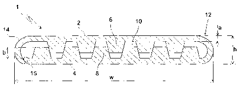
A schematic cross-sectional view of a refrigerant tube according to a first
embodiment of the invention is shown in Fig. 1. The tube is substantially flat
and
having a width w of up to 100 mm and typically about 15 to 50 mm, and a height
h of
up to 10 mm and typically about 0.5 to 5 mm. The prior art tubes made of non-
profiled
aluminium sheets have wall thicknesses of 0.25 to 0.4 mm, but the tube having
CA 02591683 2007-03-28
WO 2006/045415 PCT/EP2005/010807
7
reinforcing walls according to the invention may have thinner walls while
retaining the
same stability and pressure resistance, for example a = 0.1 to 0.3 mm,
preferably 0.15
to 0.25 mm.
The tube is made from upper wall 2 and lower wall 4 produced by folding a
rolled metal
sheet longitudinally like a hairpin. The fold is indicated at 12. On the other
side, upper
and lower wall are held together by flange 14, which ends in this example
around a
ledge 15 on the lower wall and thereby produces a mechanical fixation of upper
and
lower wall with respect to one another. Both upper and lower walls display the
same
profile of trapezoidal ridges 6, 8 which interdigitate while leaving open
spaces 10 as
fluid passages. The fluid passages are preferably up to about 0.5 mm high.
The ridges 6, 8 need not be continuous over the whole length of the tube, but
may be interrupted by gaps or cut-outs 20 forming communication holes between
adjacent fluid passages 10. The arrows in Fig. 2 indicate the direction of
flow, which is
diverted from the leftmost passage to the adjacent passages. The cut-outs 20
may be
disposed at the same longitudinal position for each ridge 8, or may be
distributed along
the length of the tube. In either case, the communication holes provide
improved
convention or turbulence of the cooling fluid between the different passages
and as a
resultant more heat transfer.
Figures 3 to 9 illustrate different ridge profile geometries according to the
above-mentioned embodiments of the invention. Fig. 3 shows the same geometry
as
Fig. 1, i.e. both walls having the same profile of trapezoidal ridges 6, 8,
each ridge 6
engaging the sides of two adjacent ridges 8 on the opposite wall. A connection
between the contacting sides 6a and 8a may be achieved by pressing the walls 2
and
4 together to achieve either a frictional engagement between the opposing
ridges, or
even a friction welded connection. The pressure may be exerted by passing the
folded
tube between two suitably adjusted rolls. In addition, the connection may be
achieved
by brazing which will be described in more detail below.
Fig. 4 and 5 display ridge geometries in which two ridges 16, 18 on the first
and
second walls only engage each other on one side, while a refrigerant passage
10 is
formed on the other side. This design allows for a larger cross-section of the
fluid
passages 10. To improve the stability further, each ridge 16, 18 engages a
corresponding groove 19 in the opposing wall. This embodiment may be designed
either with trapezoidal ridges as in Fig. 4 or with ridges having rounded
edges as in
Fig. 5.
CA 02591683 2007-03-28
WO 2006/045415 PCT/EP2005/010807
8
The third embodiment is shown in Fig. 6 using rectangular ridge profiles, but
it
may be embodied with trapezoidal profiles, too. The embodiment of Fig. 6 uses
different profiles for upper and lower walls. Therefore, it might be
preferable to
construct a fluid tube with this design from two separate sheets rather than
from one
sheet folded at midpoint. The sheets could be rolled with the same roll but at
different
reductions. In detail, the upper wall has relatively high ridges 26, each
engaging a
shallow groove 30 formed between a couple of low ridges 28 on the lower wall.
A variant of the third embodiment is shown in Fig. 7. In this design, a
rectangular
or otherwise shaped ridge 38 on the lower wall 4 engages a groove 37 formed
between a couple of ridges 36a, 36b, formed in the upper wall 2. In contrast
to Fig. 6,
the ridges 36a, 36b reach as far as the lower wall and a refrigerant passage
10 is
formed on the outer sides of ridges 36a, 36b. Since the contact surface 39
between
ridges 36 and 38 is particularly large in this embodiment, the strength of the
connection between upper and lower walls is excellent.
The fourth embodiment shown in Fig. 9a and 9b is particularly suited for a
frictional or friction welded connection between the upper and lower wall
achieved by
rolling. Fig. 9a shows the profile before rolling, and Fig. 9b shows the
profile after
rolling. As shown in Fig. 9a, the upper wall 2 is provided with main ridges 46
each
having a flat top structured in small ridges 47 and engaging the flat inner
surface of the
lower wall 4. When upper and lower walls are pressed together by rolling, the
small
ridges 47 are pressed into the inner surface of the lower wall and thus form
corresponding small ridges 48 in the lower wall. This will result in a
frictional
connection or a friction welded connection between upper and lower walls. This
connection may either be the only connection of the tube, or may be combined
with
brazing.
A variant of the fourth embodiment is shown in Fig. 8. In this design,
trapezoidal
ridges 46 on the upper wall engage the flat inner surface of the lower wall 4.
All embodiments of the profiles may be produced by rolling a metal sheet or
plate, preferably an aluminium alloy sheet. The sheet may either be blank, or
may be
clad on one or both sides with a brazing filler material. The clad layer will
preferably
have a thickness of 2 to 13% of the total thickness of the brazing sheet. The
choice of
brazing material will depend on the chosen method of "preliminary" connection
of the
tube walls, and on the selected brazing technique, as described below. To
achieve a
brazing connection between upper and lower walls, one may use a double clad
sheet
for one wall and a single clad sheet for the other.
CA 02591683 2007-03-28
WO 2006/045415 PCT/EP2005/010807
9
Representative examples of the above-shown profiles have been produced with
the profile formed roll shown in Fig. 10. The length L was 405 mm, the
diameter D was
79.66 mm, and the lengths L1 to L4 of the roll profile were 15 mm, 20.4 mm,
20.8 mm
and 15 mm, respectively. The sections L2 and L3 of the roll are provided with
18 and
28 parallel annular grooves, respectively, the detailed profiles of which are
shown in
the lower part of the drawing.
The left profile consisted of trapezoidal grooves of depth b = 0.8 mm, width
at
base f = 0.55 mm and width at top e = 0.85 mm. The sides were tilted at an
angle of a
= 11.8 with respect to the vertical. The distance between adjacent grooves
was c =
0.3 mm at the top and d = 0.6 mm at the bottom.
The smaller profile shown on the right had grooves of a depth b = 0.5 mm. The
sides of the grooves were tilted a = 12.5 with respect to the vertical, and
the grooves
had a bottom width of f = 0.35 mm and top width e = 0.55 mm. The distance
between
adjacent grooves was c = 0.2 mm at the top and d = 0.4 mm at the bottom. The
length
g was 2 mm. A photograph of the left profile is shown in Fig. 11.
This roll was used to roll an aluminium brazing sheet having a 5 % clad layer
of
brazing material. The aluminium core was made of an AA3003 aluminium alloy
according to the classification of the Aluminium Association, and the clad
layer was
made of an AA4004 aluminium alloy. The result is shown in Fig. 12. As is
apparent
from the figure, the roll produced an almost perfect trapezoidal profile of
ridges. The
clad layer accumulated mainly on the top of the ridges and the bottom of the
grooves.
Another example of a brazing sheet rolled with the rough profile depicted on
the
left of Fig. 10 and the fine profile depicted on the right of Fig. 10 is shown
in Fig. 13
and 14, respectively. In Figs. 13 and 14 the "s" stands for side and "c"
stands for
centre. This brazing sheet had a core of AA3003-type alloy and a 10 % clad
layer of an
AA4045 aluminium alloy. Again, the roll produced a very regular shape of
trapezoidal
ridges, with the best results achieved in the centre of the roll. However, the
profile at
the sides of the roll was also good.
A schematic cross-sectional of a tube made from a rolled brazing sheet product
is shown in Fig. 15 before (Fig. 15a) and after brazing (Fig. 15b) . As shown
by the
examples, the clad layer 24 is pressed mainly to the top of the ridges and the
bottom
of the grooves during rolling. During brazing, the molten filler metal flows
into the gaps
between the ridges 6 and 8 and thereby forms fillets 25 at the contact points
of the
opposing ridges.
CA 02591683 2007-03-28
WO 2006/045415 PCT/EP2005/010807
In principle all kinds of brazing technique may be used to braze the above-
described tubes and the heat exchangers comprising such tubes.
One of the preferred techniques for brazing aluminium heat exchangers utilizes
Nocolok (registered trademark) flux. Nocolok may be used with the present
5 invention, too. However, spraying the heat exchanger with flux before
brazing is a
laborious and therefore expensive process. In case the profiles of the
refrigerant tubes
are to be brazed together, the Nocolok process poses the problem of getting
the flux
inside the tubes. It is therefore more preferred to use one of the following
fluxless
brazing techniques.
10 In vacuum brazing, the parts to be brazed contain sufficient quantities
of Mg as
known in the art, such that, when heated in a brazing furnace under vacuum
conditions, the Mg becomes sufficiently volatile to disrupt the oxide layer
and permit
the underlying aluminium filler metal to flow together. This brazing technique
is
especially suitable for the present invention, since Mg will accumulate inside
the tube
and will thus cause a better brazing result. The Mg content of the inner clad
layer is
preferably 0.2 to 1 %, for example 0.6 %.
Another fluxless brazing technique uses a thin nickel layer on top of the clad
layer. Nickel reacts exothermally with the underlying aluminium alloy, thereby
disrupting the oxide layer and permitting the filler metal to flow together
and join.
Instead of Ni, Co or Fe or alloys thereof may be used, for example as known
from US-
6,379,818 and US-6,391,476.
It is further contemplated to use polymer based brazing techniques. This
method
uses an additional polymer layer on top of the clad layer containing particles
of flux
material. The polymer layer acts as an adhesive layer to the clad layer. The
polymer
will evaporate in the heat-up cycle during brazing, leaving only the flux
material on the
metal surface, for example as known from US-6,753,094.
Having now fully described the invention, it will be apparent to one of
ordinary
skill in the art that many changes and modifications can be made without
departing
from the spirit or scope of the invention as hereon described.