Note: Descriptions are shown in the official language in which they were submitted.
CA 02591881 2007-06-21
WO 2006/071073 PCT/KR2005/004603
Description
CUTTING SEGMENT OF CUTTING TOOL AND CUTTING
TOOL
Technical Field
[1] The present invention relates to a cutting segment of a cutting tool for
cutting or
drilling a brittle work piece such as stone, bricks, concrete and asphalt, and
a cutting
tool having the cutting segment. More particularly, the present invention
relates to a
cutting segment capable of improving cutting efficiency on abrasive particles
by
adequately arranging the same, and a cutting tool having the cutting segment.
[2]
Background Art
[3] To cut or drill a brittle work piece such as stone, bricks, concrete and
asphalt, an
abrasive with higher hardness than the work piece is required.
[4] The abrasives include artificial diamond particles, natural diamond
particles, boron
nitrite particles and super hard particles, of which the artificial diamond
particles are
most widely used.
[5] An artificial diamond (hereinafter referred to as "diamond") was invented
in the
1950s. The diamond, which is known to have the highest hardness out of
materials in
the earth, has been accordingly used for cutting and grinding tools due to
such
properties.
[6]
[7] Especially, the diamond has been broadly used in a stone processing field
where
stone such as granite and marble is cut and ground, and in a construction
field where a
concrete structure is cut and ground.
[8] An explanation will be given hereunder based on cutting segments and
cutting
tools that utilize diamond particles as an abrasive.
[9]
[10] Typically, a diamond tool comprises segments having diamond particles
dispersed
thereon and a metal core having the segments fixed thereto.
[11] FIG.1 illustrates an example of a segment type diamond tool.
[12] As shown in FIG.1, the segment type diamond tool includes a plurality of
segments
11, 12 fixed to a disk-shaped metal core 2, each segment 11, 12 having the
diamond
particles 5 randomly dispersed thereon.
[13] The segments are fabricated via powder metallurgy in which the segments
are
mixed with metal powder acting as a binder, molded and then sintered.
[14] When the diamond particles are mixed with metal powder, the diamond
particles
2
WO 2006/071073 PCT/KR2005/004603
are not evenly dispersed among metal powder but randomly dispersed in the
segments.
[15]
[16] For the cutting tool having the segments thereon, a relationship between
cutting
rate and useful life is contradictory. That is, if metal powder with low
abrasion
resistance is used to enhance cutting rate, useful life diminishes due to a
weak force to
retain diamond particles. In contrast, if metal powder with high abrasion
resistance is
used to increase useful life, diamond particles blunted during cutting are not
easily
released, deteriorating cutting rate in some cases.
[17]
[18] Also, in mixing the diamond particles with metal powder acting as a
binder, due to
particle size and weight difference, the diamond particles are not evenly
dispersed
among metal powder. Thus, as shown in FIG. 1, diamond particles may be
dispersed in
different concentrations according to cutting surfaces: a cutting surface 3
may have too
many diamond particles while a cutting surface 4 may have too few diamond
particles.
[19] When the diamond particles are dispersed in different concentrations
according to
the cutting surfaces as just described, both cutting rate and useful life of
the cutting
tool diminish. That is, in cutting, efficiency of the diamond particles
declines.
[20] Numerous attempts have been made to solve the problems, as demonstrated
by U.S
Patent No. 5,518,443.
[21] U.S Patent No. 5,518,443 discloses a technology capable of improving
cutting rate
and useful life by randomly dispersing diamond particles on the cutting
segments and
successively positioning a high-concentration region and a low-concentration
region in
a cutting direction.
[22]
[23] As in U.S Patent No. 5,518,443, when the high and low concentration
regions of
the diamond particles are positioned successively, in the high-concentration
region,
many diamond particles are exposed to the cutting surface. Accordingly, load
against
each diamond particle is lowered to delay wear of the diamond particles and
increase
useful life. In the region with no or few diamond particles, the diamond
particles wear
out easily so that cutting rate is boosted by fast abrasion of metal powder.
[24]
[25] However, with respect to aforesaid U.S Patent No. 5,518,443, the diamond
particles are randomly dispersed and are not spaced properly in the high-
concentration
region, leading to uniform concentration. Therefore there is a limit in
improving
cutting rate and useful life.
[26]
[27] To solve a problem of segregation of the diamond particles, a patterning
technology of diamond particles was suggested, as shown in FIG.2.
CA 02591881 2007-06-21
3
WO 2006/071073 PCT/KR2005/004603
[28] FIG.2 illustrates an example of a segment type diamond too120 patterned
with the
diamond particles.
[29] As shown in FIG.2, the diamond particles are patterned or regularly
dispersed in
each segment 21, 22.
[30] If a work piece is cut via the segments, the diamond particles are evenly
dispersed
and uniformly spaced on the cutting surface, leading to uniform popularity. Ac-
cordingly, all diamond particles are involved in a cutting process continually
so that
efficiency of the cutting process increases.
[31]
[32] However if the above-identified patterning technology is applied to the
cutting
segments with low-concentration of diamond particles (the number of the
diamond
particles per unit volume of the segment), there is a limit in improving
cutting rate and
useful life.
[33] U.S Patent No. 6,110,031 teaches a technology of enhancing cutting rate
and useful
life by forming outer layers with high abrasion resistance on both sides and
inner
layers between the outer layers. The inner layers are arranged to have a high
abrasion
resistance part and a relatively low abrasion resistance part regularly
dispersed in a
cutting direction and in a direction perpendicular to the cutting direction.
[34]
[35] But in U.S Patent No. 6,110,031, a high-concentration region and a low-
concentration region in the inner layers are evenly dispersed across the
segments in a
cutting direction or in a direction perpendicular to the cutting direction. As
a result, in
the low-concentration region, useful life cannot be improved, whereas in the
high-
concentration region, the protrusion height of the diamond particles cannot be
maximized due to an adjacent low-abrasion resistance area. Thus an effect of
better
cutting rate is insignificant.
[36]
Disclosure of Invention
Technical Problem
[37] The present invention has been made to solve the foregoing problems of
the prior
art and it is therefore an object of the present invention to provide a
cutting segment
capable of improving cutting rate and useful life by arranging abrasive
particles
adequately and increasing cutting efficiency thereof, and a cutting tool
having the
same.
[38]
Technical Solution
[39] The present invention will be explained hereunder.
CA 02591881 2007-06-21
CA 02591881 2007-06-21
4
WO 2006/071073 PCT/KR2005/004603
[40] According to an aspect of the invention for realizing the object, there
is provided a
cutting segment of a cutting tool for cutting a work piece on a cutting
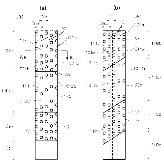
surface, the
cutting segment comprising a number of abrasive particles arranged in a
plurality of
rows extended along a cutting direction, the abrasive rows being placed side
by side
with one another across the cutting direction and stacked vertically from the
cutting
surface, wherein each of the abrasive rows includes high-concentration parts
and low-
concentration parts along the cutting direction on the cutting surface, the
high-
concentration parts showing a concentration higher than an average
concentration of
the each abrasive row, and the low-concentration parts showing a concentration
lower
than the average concentration, and wherein the high-concentration parts are
grouped
together to form a high-concentration area on the cutting surface and low-
concentration parts are grouped together to form a low-concentration area on
the
cutting surface, and the high-concentration area and the low-concentration
area are
extended to both sides of the segment, respectively, wherein the low-
concentration
areas have a polygonal contour on the cutting surface, and wherein the high-
concentration area alternates with the low-concentration area along the
cutting
direction.
[411
[42] According to another aspect of the invention for realizing the object,
there is
provided a cutting tool having a cutting segment thereon.
[43] A cutting segment of a cutting tool for cutting a work piece on a cutting
surface,
the cutting segment comprising a number of abrasive particles arranged in a
plurality
of rows extended along a cutting direction, the abrasive rows being placed
side by side
with one another across the cutting direction and stacked vertically from the
cutting
surface, wherein the abrasive rows include outer abrasive rows placed in both
sides of
the segment and a plurality of inner abrasive rows placed between the outer
rows,
wherein at least one of the outer rows has abrasive particles arranged with
uniform
concentration, wherein each of the inner rows includes high-concentration
parts and
low-concentration parts along the cutting direction on the cutting surface,
the high-
concentration parts showing a concentration higher than an average
concentration of
the each abrasive row, and the low-concentration parts showing a concentration
lower
than the average concentration, wherein the high-concentration parts are
grouped
together to form a high-concentration area on the cutting surface and low-
concentration parts are grouped together to form a low-concentration area on
the
cutting surface, wherein the low-concentration area has a polygonal contour on
a
cutting surface, and wherein the high-concentration area alternates with the
low-
concentration area along the cutting direction.
[44]
5
WO 2006/071073 PCT/KR2005/004603
[45] According to still another aspect of the invention for realizing the
object, there is
provided a cutting tool having a cutting segment thereon.
[46] The present invention is applied to a cutting segment of a cutting tool
for cutting or
drilling a brittle work piece such as stone, bricks, concrete and asphalt.
[47] The cutting segment of the cutting tool comprises abrasive particles
carrying out
cutting in cutting a work piece and a metal binder fixing the abrasive
particles.
[48]
[49] According to still a further aspect of the invention for realizing the
object, there is
provided an arrangement of abrasive particles.
[50] For example, with respect to the segments of the invention, the cutting
segment
comprises a number of abrasive particles arranged in a plurality of rows
extended
along a cutting direction, the abrasive rows being placed side by side with
one another
across the cutting direction and stacked vertically from the cutting surface.
[51] A gap between one of outer rows placed in both sides of the segment and
an
adjacent inner abrasive row is 2.0 times of or less than the average diameter
of the
abrasive particles, and a gap between inner rows placed between the outer rows
is 4.0
times of or less than the average diameter of the abrasive particles, and more
preferably, 1.5 to 2.5 times the average diameter of the abrasive particles.
[52]
[53] The abrasive rows are stacked vertically from the cutting surface.
[54] Preferably, the abrasive rows are successively protruded from the cutting
surface
with a predetermined pattern in cutting a work piece.
[55] The abrasive rows include high-concentration parts and low-concentration
parts
along the cutting direction from the cutting surface, the high-concentration
parts
showing a concentration higher than an average concentration of the each row
whereas
the low-concentration parts showing a concentration lower than the average con-
centration.
[56]
[57] The low-concentration part may have no abrasive particles.
[58] The high-concentration parts are grouped together to form a high-
concentration
area on the cutting surface and low-concentration parts are grouped together
to form a
low-concentration area.
[59] If the low-concentration parts do not have any abrasive particles as just
described,
the low-concentration area may not have any abrasive particles either.
[60] The low-concentration areas have a contour consisting of lines that
define a
polygon on the cutting surface.
[61]
[62] Preferably, the ratio of the mean length of the high-concentration area
to the mean
CA 02591881 2007-06-21
6
WO 2006/071073 PCT/KR2005/004603
length of the low-concentration area is 0.3 to 2Ø
[63] The high-concentration area and low-concentration area are extended to
both sides
of the segment.
[64] The high-concentration area alternates with the low-concentration area
along the
cutting direction.
[65] To give another example regarding the segments of the invention, the
cutting
segment comprises a number of abrasive particles arranged in a plurality of
rows
extended along a cutting direction. The abrasive rows are placed side by side
with one
another across the cutting direction and stacked vertically from the cutting
surface.
[66]
[67] Preferably, the abrasive rows are successively protruded from the cutting
surface
with a predetermined pattern in cutting a work piece.
[68] Each of the rows includes outer rows placed in both sides of the segment
and a
plurality of inner rows placed between the outer rows.
[69] Preferably, a gap between one of outer rows placed in both sides of the
segment
and an adjacent inner row is 2.0 times of or less than the average diameter of
the
abrasive particles. Also, preferably, a gap between inner rows placed between
the outer
rows is 4.0 times of or less than the average diameter of the abrasive
particles and
more preferably, 1.3 to 2.5 times.
[70] At least one of outer rows has abrasive particles arranged with uniform
con-
centration.
[71] That is, out of outer rows, one has abrasive particles arranged with
uniform con-
centration and the other has abrasives arranged in the same way as inner rows,
or all
rows may be arranged with uniform concentration.
[72]
[73] Each of the inner rows includes high-concentration parts and low-
concentration
parts in the cutting direction from the cutting surface, the high-
concentration parts
showing a concentration higher than an average concentration of the each row
whereas
the low-concentration parts showing a concentration lower than the average con-
centration.
[74] The low-concentration parts may have no abrasive particles.
[75] The low-concentration area has a contour consisting of lines that define
a polygon
on the cutting face.
[76] The ratio of the mean length of the high-concentration area to the mean
length of
the low-concentration area is 0.3 to 2Ø
[77] The inner rows are arranged in such a way that the high-concentration
parts are
grouped together to form a high-concentration area on the cutting surface
while the
low-concentration parts are grouped together to form a low-concentration area
on the
CA 02591881 2007-06-21
7
WO 2006/071073 PCT/KR2005/004603
cutting surface.
[78] If the low-concentration parts do not have any abrasive particles as just
described,
the low-concentration area may not have any abrasive particles either.
[79]
[80] Further, preferably, the inner rows are arranged in such a manner that an
equal
number of abrasive particles are protruded with uniform concentration at
uniform
spaces in a cutting direction.
[81] According to the present invention, the inner rows adjacent to the outer
rows may
have abrasive particles arranged with uniform concentration, and the number of
inner
rows allowing arrangement of abrasive particles with uniform concentration
should be
less than 1/2 of the total inner rows.
[82] The high-concentration alternates with the low-concentration area along
the cutting
direction.
[83]
Brief Description of the Drawings
[84] The above and other objects, features and other advantages of the present
invention
will be more clearly understood from the following detailed description taken
in
conjunction with the accompanying drawings, in which:
[85] FIG.1 is an example of a diamond tool having diamond particles randomly
dispersed on a cutting surface of cutting segments;
[86] FIG.2 is an example of the diamond tool having diamond particles
regularly
dispersed on a cutting surface of cutting segments;
[87] FIG.3 is a schematic view illustrating a cutting surface of a cutting
segment
according to the invention, in which (a) shows a low-concentration area having
a
contour with two sides perpendicular to a cutting direction, and (b) shows a
low-
concentration area having a contour with two sides slanted from the cutting
direction;
[88] FIG.4 is a schematic view showing arrangement of abrasive particles
protruded
from the cutting surface seen from the segment side in cutting, in which (a)
shows ar-
rangement by a conventional cutting segment, and (b) shows arrangement by a
cutting
segment of the invention;
[89] FIG.5 is a view showing arrangement of abrasive particles in which the
abrasive
rows are stacked vertically from the cutting surface according to the
invention;
[90] FIG.6 is a schematic view showing another example of the cutting segment
according to the invention, in which (a) shows abrasive particles vertically
stacked
from the cutting surface, (b) shows arrangement of abrasive particles
dispersed on an
upper face, and (c) shows arrangement of the abrasive particles dispersed on a
lower
face;
CA 02591881 2007-06-21
8
WO 2006/071073 PCT/KR2005/004603
[91] FIG.7 is a schematic view showing still another example of the cutting
segment
according to the invention, in which(a) shows arrangement of abrasive
particles of the
cutting segment, and (b) shows arrangement of abrasive particles on the
cutting
surface;
[92] FIG.8 is a sectional view of the cutting segment taken along the line A-A
in FIG.3.
[93] FIG. 9 is a configuration view of cutting segments according to the
invention;
[94] FIG. 10 is a configuration view of cutting segments according to the
invention.
[95]
Mode for the Invention
[96] Preferred embodiments of the present invention will now be described in
detail
with reference to the accompanying drawings.
[97] FIG.3 shows an example of a cutting segment of the invention.
[98] As shown in FIG.3, the cutting segment 100 of the invention includes rows
of
abrasive particles 101 in which the abrasive particles 105 are arranged in a
cutting
direction. The cutting segment 100 according to the invention includes a
number of
abrasive particles arranged in a plurality of rows extended along a cutting
direction.
The abrasive rows 101 are placed side by side with one another across the
cutting
direction and stacked vertically from the cutting direction.
[99]
[100] Preferably, the number of the abrasive rows 101 is at least 4.
[101] In cutting, a high-concentration area 110a sustains a big cutting load.
Thus out of
the abrasive rows 101, if a gap Dout between one of outer rows lOla positioned
in the
side and an adjacent inner row 101b is too large, outer abrasive rows fall off
toward the
side of the cutting segment during cutting, rendering it impossible to
continue with
cutting. As a result, preferably, a gap Dout between one of outer rows lOla
and an
adjacent inner rows is 2.0 times of or less than the average diameter of the
abrasive
particles.
[102]
[103] In contrast, if a gap Din between inner rows 101b placed between the
outer rows
lOla is too large, a part of the segment with no abrasive particles among the
abrasive
rows is deeply dented so that the abrasive particles easily fall off, possibly
dete-
riorating useful life of the cutting tool. Therefore, a gap Din between the
inner rows
101b positioned between the outer rows lOla is preferably 4.0 times of or less
than the
average diameter of the abrasive particles, or more preferably 1.3 to 2.5
times the
average diameter of the abrasive particles.
[104]
[105] The abrasive rows are stacked vertically from the cutting surface 111.
CA 02591881 2007-06-21
9
WO 2006/071073 PCT/KR2005/004603
[106] The abrasive rows 101 include high concentration parts 1011a, 1011b and
low con-
centration parts 1012a, 1012b along the cutting direction from the cutting
surface 111.
The high concentration parts show a concentration higher than an average con-
centration of the each abrasive row, whereas the low-concentration parts show
a con-
centration lower than the average concentration.
[107] The low-concentration parts 1012a,1012b may not have abrasive particles.
[108] The abrasive rows 101 are arranged in such a manner that high-
concentration parts
1011a, 1011b are grouped together to form a high-concentration area 110a on
the
cutting surface and low-concentration parts 1012a,1012b are grouped together
to form
a low-concentration area 110b.
[109]
[110] As just described, if the low-concentration parts 1012a,1012b do not
have any
abrasive particles, the low-concentration area 110b may not have any abrasive
particles
either.
[111] The high-concentration area 110a and low-concentration area 110b are
extended to
both sides 112 of the segment, respectively.
[112] The high-concentration area 110a alternates with the low-concentration
area 110b
along the cutting direction.
[113]
[114] As shown in FIG. 3a, the low-concentration area 110b has a polygonal
shape, par-
ticularly a rectangular contour 120a on the cutting surface, and as shown in
FIG. 3b,
the low-concentration area 110b has a polygonal shape, particularly a paral-
lelogrammic contour 120b.
[115] Preferably, the ratio L/A of length L of the high-concentration area
110a to length
A of the low-concentration area 110b is 0.3 to 2Ø
[116] The high-concentration area 110a alternates with the low-concentration
area 110b
along the cutting direction.
[117]
[118] There should be at least one high-concentration area 110a and one low-
concentration area 110b, respectively.
[119] According to the invention, the high-concentration area 110a and low-
concentration area 110b on the cutting surface of the cutting segment allow
cutting
under a lower load. Consequently the cutting tool suffers from lower impact,
leading to
less vibration and noise during cutting. Especially, the present invention
enhances
cutting rate if the high-concentration area 110a and the low-concentration
area 110b on
the cutting surface of the segment have proper lengths and numbers, which will
be
explained hereunder.
[120]
CA 02591881 2007-06-21
10
WO 2006/071073 PCT/KR2005/004603
[121] FIG.4 shows protrusion of the abrasive particles seen from the segment
side in
cutting a work piece via the segment having abrasive particles regularly
arranged
thereon. FIG.4 (a) shows the segment marking no change in the concentration
area
while FIG.4 (b) shows the segment marking a change in the concentration area.
[122] As shown in FIG. 4(a), for the segment having the diamond particles
regularly
arranged without any change in the concentration area, all abrasive particles
are
protruded with almost equal heights.
[123]
[124] In this case, protruded abrasive particles located in a rear part of the
segment in a
cutting direction are buried by a tail of preceding abrasive particles,
sustaining less
cutting load. As a result, a sharp edge of abrasive particles is glazed,
deteriorating
cutting rate.
[125]
[126] Meanwhile, as shown in FIG. 4(b), for the segment comprising the high-
and low-
concentration areas alternating with each other according to the invention,
abrasive
particles A, B, C positioned in the front of the concentration area indicate a
substantial
height h of protrusion thereof.
[127] This is because relatively severe abrasion in an area with low
concentration or no
diamond particles leads to a high protrusion of abrasive particles in the
front of a high
concentration area.
[128] Also, abrasive particles positioned in the back of a high concentration
area in a
cutting direction are less buried by a tail of the abrasive particles
positioned in the
front, thereby improving cutting rate of each abrasive particle.
[129]
[130] That is, cutting rate is boosted in proportion to the numbers of
segments in the
cutting tool of the equal diameter. The present invention enhances cutting
rate by ac-
complishing an effect as if a segment has a plurality of sub-segments.
[131]
[132] Further, with respect to polygonal contours of the low-concentration
area 110b, the
contour may have at least one side slanted in a direction perpendicular to the
cutting
direction. This reduces impact resulting from possible severe intermission
that may be
caused by the high-concentration area 110a and the low-concentration area 110b
al-
ternating with each other.
[133] Also, an explanation will be given hereunder regarding effects of the
high- and
low-concentration areas design on the cutting rate.
[134]
[135] Typically, it is assumed that abrasive particles are large-sized when a
hard work
piece is cut with cutting speed accelerated via high-powered machine. In this
case,
CA 02591881 2007-06-21
11
WO 2006/071073 PCT/KR2005/004603
cutting rate and useful life can be enhanced by lowering the ratio of the high-
concentration area and increasing the number of the high-concentration areas.
[136] Moreover, preferably, the number of the abrasive rows stacked in the
segment
should be increased so as to narrow a gap Dout between the outer rows and the
inner
rows, and a gap Din between the inner rows so that a groove should not be too
deep.
[137]
[138] Thus, abrasive particles and average concentration of the cutting
segment should be
decided in accordance with a working condition, a machine and a work piece,
and then
the number of abrasive rows, the number and length of the high- and low-
concentration
areas and local concentration therein should be decided .
[139]
[140] FIG.5 shows an example in which abrasive particles of the segment are
stacked
vertically from the cutting surface.
[141] As shown in FIG.5, in the cutting segment 200 of the invention, a number
of
abrasive particles arranged in a plurality of rows extended along a cutting
direction and
the abrasive rows are stacked vertically from the cutting face.
[142] Preferably, the abrasive rows are stacked in such a manner that in
cutting a work
piece, new abrasive particles 205b can be protruded among initially protruded
abrasive
particles 205a.
[143] In FIG.5, numera1210a designates the high-concentration area, while
numeral
210b designates the low-concentration area.
[144] As in FIG.5, the abrasive rows are stacked vertically from the cutting
surface so
that the abrasive particles are successively protruded at uniform intervals
and with a
predetermined pattern in cutting a work piece.
[145]
[146] FIG.6 shows another example of the cutting segment according to the
invention.
[147] In the invention, as shown in FIG.6 (a), the abrasive rows are stacked
in such a
manner that a low-concentration part of a lower abrasive row is placed
corresponding
to a high-concentration part of an overlying abrasive row in a direction
perpendicular
to the cutting surface.
[148] In case of stacking as just described, a gap d between an overlying
abrasive row
and a lower abrasive row should be 1/2 to 2/3 of the abrasive particle size.
[149] In case of stacking as just described, if abrasive particles on an upper
cutting
surface have a first area and a third area protruded in a direction
perpendicular to a
cutting surface as in FIG. 6(b), abrasive particles on a lower cutting surface
will have a
second area and a fourth area protruded as in FIG. 6(c).
[150]
[151] FIG.7 (a) and (b) shows still a further example of the segment according
to the
CA 02591881 2007-06-21
12
WO 2006/071073 PCT/KR2005/004603
invention.
[152] As shown in FIG.7 (a) and (b), abrasive particles 305 on a cutting
segment 300 are
arranged in rows. On a cutting surface 311 a plurality of abrasive rows are
arranged in
a direction perpendicular to a cutting direction.
[153] The abrasive particle rows 301 are stacked vertically from the cutting
surface 311.
[154] The abrasive rows 301 on a certain face include outer rows 301a placed
in both
sides of the segment and a plurality of inner rows 301b placed between the
outer rows
301a.
[155]
[156] Preferably, a gap between one of outer rows 301a and an adjacent inner
row 301b
is 2.0 times of or less than the average diameter of the abrasive particles. A
gap
between inner rows 301b is preferably 4.0 times of or less than the average
diameter of
the abrasive particles, and more preferably 1.3 to 2.5 times the average
diameter of the
abrasive particles.
[157] At least one of the outer rows 301a has abrasive particles arranged with
uniform
concentration.
[158] That is, one of outer rows 301a may have abrasive particles arranged
with uniform
concentration and the other one may have abrasive particles arranged in the
same way
as the inner rows 301b. Alternatively, both of the outer rows 301a may be
arranged
with uniform concentration.
[159]
[160] The inner rows 301b include high concentration parts 3011b and low
concentration
parts 3012b in a cutting direction on a cutting surface 311, in which the high-
concentration parts 3011b show concentration higher than an average
concentration of
the each row and the low-concentration parts show a concentration lower than
the
average concentration.
[161] The inner rows 301b are arranged in such a manner that high
concentration parts
3011b are grouped together to form a high concentration area 310a on the
cutting
surface 311 and low concentration parts 3012b are grouped together to form a
low con-
centration area 3101b1 on the cutting surface 311.
[162] The low-concentration area 310b has a polygonal shape, particularly, a
rectangular
contour 320.
[163] The high-concentration parts 3011b of the each inner row 310b are
grouped
together to form the high-concentration area 310a. Preferably, the ratio L/A
of length L
of the high-concentration area 310a to length A of the low-concentration area
310b is
0.3 to 2Ø
[164] The low concentration parts 3012b may have no abrasive particles as
shown in
FIG.7.
CA 02591881 2007-06-21
13
WO 2006/071073 PCT/KR2005/004603
[165] If the low concentration parts 3012b of the inner rows 301b do not have
any
abrasive particles, the low concentration area 310b may not have any abrasive
particles
either.
[166] Preferably, the inner rows 301b are arranged in such a manner that the
abrasive
particles can be protruded in a cutting direction at uniform intervals and
with uniform
concentration.
[167] The high concentration area 310a alternates with the low concentration
area 310b
in a cutting direction.
[168] Abrasive particles arranged in the high concentration area 310a have
predetermined
patterns.
[169] Abrasives used in the invention are not specifically limited but
preferably diamond
particles are used.
[170]
[1711 In cutting a work piece according to the invention, as shown in FIG.8,
parts with no
abrasive particles among the abrasive rows suffer abrasion with proper depths
during
cutting process, with grooves leading from the front of the segment to the end
in a
cutting direction. This allows debris to be easily discharged along the deep
grooves and
increases protrusion height h of the abrasive rows placed between the grooves
so as to
cut a work piece more deeply, thereby improving cutting rate.
[172] Moreover, for the cutting segment of the invention, the abrasive
particles protruded
from the cutting surface are assembled in a certain area in a cutting
direction and
dispersed in rows without different concentrations. Therefore each abrasive
particle
shares work load so that a cycle of abrasion for the abrasive particles is
delayed and
useful life thereof is lengthened.
[173]
[174] FIG. 9 shows examples of the cutting segment including a plurality of
the low-
concentration area according to the invention.
[175] Referring to FIG. 9(a), each of the low-concentration areas has a
parallelogrammic
contour, and the parallelogrammic contours are arranged parallel to each
other.
Referring to FIG. 9(b), each of the low-concentration areas has a
parallelogrammic
contour, and the parallelogrammic contours are arranged nonparallel to each
other.
[176] Also, as shown in FIG. 9(C), each of the low-concentration areas has a V-
shaped
contour, and the V-shaped contours are oriented to face each other. As shown
in FIG.
(d), each of the low-concentration areas has an arrow-shaped contour with both
ends
facing opposite directions.
[177] The invention provides a cutting tool with a cutting segment fabricated
as
described above.
[178] A saw blade, a core bit and a grinding wheel may be used for the cutting
tool.
CA 02591881 2007-06-21
14
WO 2006/071073 PCT/KR2005/004603
[179] The invention will be explained in greater detail with the examples
which follow.
[180]
[1811 Example 1
[182] A saw blade (inventive product 1) fabricated according to the invention
and a saw
blade (conventional product 1-3) fabricated according to conventional method
were
used to examine cutting rate and useful life in cutting a work piece, and the
results are
shown in table 2 below.
[183]
[184] Inventive product 1 is a cutting segment utilizing diamond particles as
abrasives
and having a length L of 40, a thickness T of 3.2, a width W of 10.0, a
diameter of
168R (14 inches) and an average concentration of 0.75Conc. For both outer rows
and
inner rows of diamond particles, the number of high-concentration areas n is
3. Each
row had an average concentration of diamond particles dispersed thereon at a
pre-
determined rate. Therefore, the high-concentration areas each have a local con-
centration of 1.33 Conc.
[185]
[186] Rows of diamond particles include 2 outer rows and 4 inner rows. Diamond
particles used in the entire rows are MBS-955 available from G.E Corp. in
U.S.A, and
US 50/60 mesh with average particle diameter of 2900.
[187] As a gap of the rows, Dout is 0.64mm, and Din is 0.64mm.
[188] Inventive product 1 is shaped as in FIG. 10 (a) with detailed dimensions
set forth in
Table 1. In Inventive product 1, the low-concentration area has a
parallelogrammic
contour and the contour has two sides slanted at an angle of 51.34 degree with
respect
to a vertical line of the cutting surface.
[189]
[190] Conventional product 1 is a saw blade that uses a cutting segment, which
is 40L in
length, 3.2T in thickness, and 0.75Conc. in average concentration and has
diamond
particles randomly dispersed. The diamond particles are MBS-955, US 50/60 mesh
with average particle diameter of 2900.
[191] Conventional product 2 is equal to conventional product 1 in terms of
shape of
cutting segment, diamond type and particle diameter, but has 0.9Conc. of
average con-
centration.
[192]
[193] In conventional product 3, a cutting segment is quartered at equal
intervals in a
cutting direction and diamond particles are randomly dispersed in such a
manner that
concentration in the front and third parts in a cutting direction is 1.5Conc.
[194] Conventional product 3 is equal to conventional product 1 in terms of
shape of a
cutting segment, diamond type and particle diameter.
CA 02591881 2007-06-21
15
WO 2006/071073 PCT/KR2005/004603
[195] A 14 inch bridge sawing machine of 1800rpm available from PEDRINI Corp.
was
used.
[196] The products were cut with 30mm of depth and 288m of cutting length.
[197] Inventive product 1, conventional product 1, conventional product 2, and
con-
ventional product 3 used mixed powder of cobalt, iron and copper of the same
composition as metal powder (binder)
[198]
[199] Table 2 shows a cutting index of power (kWh) required in cutting a work
piece of
10. The smaller index means a better cutting performance. In addition, the
bigger index
for useful life means longer useful life since the index for useful life
indicates the
amount of work done (0) for 1mm abrasion of a cutting segment.
[200]
[2011 Table 1
Shape
L11 L21 L1 L12 L22 L2 L13 L23 L3 All A21 Al A12 A22 A2
6 8 8 8 8 6 10 8 8 8 8 8 8 :8:]
[202]
[203] Table 2
Sample No. 1 Inventive Conventional Conventional Conventional
product 1 product 1 product 2 product 3
Cutting 1.182(100%) (80.1%) (75.2%) (85.3%)
index[kWh/0]
Usefullife[0/mm] 4.341(100%) (77.3%) (97.3%) (81.2%)
[204]
[205] As shown in table 2, inventive product 1 is superior to conventional
products 1, 2,
3 in terms of cutting rate and useful life. Inventive product 1 has diamond
particles
arranged in rows and includes high concentration and low concentration areas
according to the invention. Conventional products 1, 2 have diamond particles
randomly arranged whereas conventional product 3 has high concentration and
low
concentration areas with diamond particles randomly arranged.
[206]
[207] Example 2
[208] A gap of the diamond rows arranged on a cutting segment, or a gap Dout
between
an outer row and an inner row and a gap Din between inner rows was adjusted as
in
CA 02591881 2007-06-21
16
WO 2006/071073 PCT/KR2005/004603
Table 3 to fabricate the cutting segment and manufacture a saw blade
therewith. Then
cutting rate and useful life were examined. Table 5 shows results of cutting
rate test
and table 6 shows those of useful life.
[209] The cutting segment is shaped as in FIG. 10(b). The low-concentration
area has a
contour symmetrical about the center of the cutting surface in a cutting
direction. The
low-concentration area has an arrow-shaped hexagonal contour with its
dimensions set
forth in Table 4.
[210]
[211] Diamond particles used herein is US mesh 40/50 available from G.E Corp
of
U.S.A., with average diameter of 3700. The cutting segment is 40L in length,
3.6T in
thickness, 8.5W in width, and 168R (14 inches). The number of and the gap
between
diamond rows are shown in Table 3.
[212] For the cutting segments, the average concentration of diamond is
0.9Conc.. When
the high-concentration area has 90% average concentration and the low-
concentration
area has 10% average concentration, the high-concentration has a local
concentration
of 1.62Conc. and the low-concentration has a local concentration of 0.18Conc.
The
number of the high-concentration areas n is 4. The low-concentration area has
a
contour with two sides angled at 51.34 degree with respect to a vertical line
of the
cutting segment.
[213] The contour has both sides identically angled owing to its configuration
symmetrical about the center of the cutting segment.
[214] A 6.5I1P, 4200RPM handcut available from STHIL Corp. was used as a
cutting
machine and work pieces of granite were used. The work pieces were cut with
20mm
of depth and 240m of cutting length.
[215]
[216] Meanwhile, cutting rate and useful life were measured for a saw blade
(conventional product 4), which was manufactured under the same conditions as
samples of Table 3 except for random arrangement of diamond particles. Cutting
rate
was 660.3 0/min and useful life was 7.220/mm.
[217] For cutting rate and useful life in Tables 5 and 6 below, measured
values were
indicated by placing cutting rate and useful life of conventional product 4 at
100% re-
spectively.
[218]
[219] Table 3
Sample 1 Sample 2 Sample 3 Sample 4 Sample 5 Sample 6
Number 5 5 5 6 7 8
of Layers
CA 02591881 2007-06-21
17
WO 2006/071073 PCT/KR2005/004603
Dout* 0.592mm( 0.354mm( 0.40mm(1.3 0.563mm(l. 0.50mm(1. 0.374mm(
2.04 1.22 times 7 times) 94 times) 72 times) 1.29
times) times)
Din** 0.576mm( 0.734mm( 0.705mm(2Ø446mm(1. 0.383mm( 0.374mm(
1.98 2.53 43 times) 54 times) 1.32 1.29
times) times) times) times)
[220] *Dout: Ratio to the average diamond diameter
[221] **Din: Ratio to the average diamond diameter
[222]
[223] Table 4
Shape L11 L21 L1 L12 L22 L2 L13 L23 L3 L14 L24 L4
6 6 5 5 5 5 5 5 5 4 4 5
All A12 A1 A12 A22 A2 A13 A24 A3
6.67 6.67 6.67 6.66 6.66 6.66 6.67 6.67 6.67
[224]
[225] Table 5
Sample Sample 1 Sample 2 Sample 3 Sample 4 Sample 5 Sample 6
No.
Cutting (113.2%) (115.1%) (120.9%) (128.4%) (108.3%) (101.1%)
rate[0/min]
[226]
[227] Table 6
Sample Sample 1 Sample 2 Sample Sample 4 Sample 5 Sample 6
No. 3
Useful (108.2%) (107.1%) (117.1%) (125.2%) (128.7%) (129.2%)
life[0/mm]
[228]
[229] As shown in Tables 5 and 6, samples 1 to 6 according to the invention
are superior
to conventional product 4. However, samples 3,4,5 are superior to samples
1,2,6 in
terms of cutting rate and useful life. For samples 3,4,5, the ratio of a gap
Dout between
an outer row and an inner row to the average diamond diameter is less than 2.0
and the
ratio of a gap Din between inner rows to the average diamond diameter is 1.3
to 2.5.
For sample 1, the ratio of a gap Dout between an outer row and an inner row to
the
CA 02591881 2007-06-21
18
WO 2006/071073 PCT/KR2005/004603
average diamond diameter is greater than 2Ø For sample 2, the ratio of a gap
Din
between inner rows to the average diamond diameter is greater than 2.5. For
sample 6,
the ratio of a gap Din between inner rows to the average diamond diameter is
less than
1.3.
[230]
[231] Example 3
[232] A cutting segment was fabricated by varying the mean length L of the
high-
concentration area, and the mean length A of the low-concentration area.
Diamond
particles were locally dispersed only on the high-concentration area without
being
dispersed on the low-concentration area. The cutting segment was used to
fabricate a
saw blade, and cutting rate and useful life thereof were measured. The results
are
shown in Tables 9 and 10.
[233]
[234] Samples 7, 9, 10 shown in Tables 9 and 10 are shaped as in FIG. 10(a).
Also,
sample 8 is shaped as in FIG. 10(b) and sample 11 is shaped as in FIG. 10(c).
Tables 7
and 8 show detailed dimensions, the number of the high-concentration areas,
local con-
centration, a ratio L/A of the mean length L of the high-concentration area to
the mean
length of the low-concentration area.
[235] The low-concentration area has a parallelogrammic contour and the
contour has
two sides slanted at an angle of 32 degree with respect to a vertical line of
the cutting
segment.
[236] A machine used was an engine-driven table-type cutting machine available
from
EDCO Corp. having 4.5 horse power and 3500RPM, and granite and concrete were
used for a work piece.
[237] Work pieces of granite were cut with 20mm of depth and 240m of cutting
length,
while work pieces of concrete were cut with 30mm of depth and 240m of cutting
length.
[238] Cutting rate and useful life were examined through the aforesaid cutting
tests. The
results of cutting rate and useful life are shown in Tables 9 and 10,
respectively.
[239]
[240] Table 7
n L11 L21 L1 L12 L22 L2 L13 L23 L3
A11 A21 A1 L12 A22 A2 L13 A23 A3
Sample7 3 354 444 534
141414 141414
Sample8 4 243 333 333
CA 02591881 2007-06-21
19
WO 2006/071073 PCT/KR2005/004603
9.33 9.33 9.33 9.33 9.33 9.33 9.33 9.33 9.33
Sample 9 3 8.33 10.33 9.33 9.33 9.33 9.33 10.33 8.33 9.33
666 666
Sample 10 3 9 11 10 101010 11910
555 555 555
Sample11 4 6.58.57.5 7.57.57.5 7.57.57.5
3.33 3.33 3.33 3.33 3.33 3.33 3.33 3.33 3.33
[2411
[242] Table 8
L14 L24 L4 Local concentration L/A
Sample 7 3.0 Conc. 0.29
Sample 8 423 3.0 Conc. 0.32
Sample 9 1.29 Conc. 1.56
Sample 10 1.2 Conc. 2
Sample 11 8.56.57.5 1.2 Conc. 2.25
[243]
[244] Table 9
Sample 7 Sample 8 Sample 9 Sample 10 Sample 11
Granite[0/min] 673.5 705.9 740.5 714.6 663.1
Concrete[0/min] 849.2 908.2 982.3 923.1 836.7
[245]
[246] Table 10
Sample 7 Sample 8 Sample 9 Sample 10 Sample 11
Granite [0/mm] 16.11 16.52 17.62 17.02 16.76
CA 02591881 2007-06-21
20
WO 2006/071073 PCT/KR2005/004603
Concrete[0/mm] 18.25 19.08 21.31 20.93 19.27
[247]
[248] As shown in Tables 9 and 10, cutting rate and useful life are superior
when the
ratio L/A of the mean length L of the high-concentration area to the mean
length A of
the low-concentration area is 0.3 to 2Ø
[249]
Industrial Applicability
[250] As set forth above, according to the present invention, cutting
efficiency of the
abrasive particles can be elevated by properly arranging the abrasive
particles. As a
result, for the cutting segments requiring high concentration, superior
cutting rate and
longer useful life can be ensured at a cheap price. Also, for the cutting
segments
requiring low concentration, superior cutting rate and longer useful life are
attainable
as equally as the cutting segments requiring high concentration.
[2511
[252] While the present invention has been shown and described in connection
with the
preferred embodiments, it will be apparent to those skilled in the art that
modifications
and variations can be made without departing from the spirit and scope of the
invention
as defined by the appended claims.
CA 02591881 2007-06-21