Note: Descriptions are shown in the official language in which they were submitted.
CA 02592669 2011-01-27
COMBINATION SEAL AND RESTRAINING SYSTEM FOR PLASTIC PIPE
Description
Technical Field
The present invention relates generally to the field of pipe connections, and
in particular,
to a dual function, self restraining sealing system that is used to form a
secure pipe
connection between two plastic pipes and to a method of manufacturing the
same.
Background Art
Pipes are commonly used for the conveyance of fluids under pressure, as in
city water
lines. They may also be used as free-flowing conduits running partly full, as
in drains and
sewers. Pipes for conveying water in appreciable quantities have been made of
steel,
cast iron, concrete, vitrified clay, and most recently, plastic including the
various
polyolefins and PVC.
It is well known in the art to extrude plastic pipes in an elongated
cylindrical configuration
of a desired diameter and to then cut the extruded product into individual
lengths of
convenient size suitable for handling, shipping and installing. Each length of
pipe is
enlarged or "belled" at one end sufficiently to join the next adjacent pipe
section by
receiving in the female, belled end the unenlarged or "spigot" male end of the
next
adjacent length of pipe. The inside diameter of the bell is formed
sufficiently large to
receive the spigot end of the next section of pipe with sufficient clearance
to allow the
application of packing, caulking, elastomeric gaskets or other sealing devices
designed
to prevent leakage at pipe joints when a plurality of pipe lengths are joined
to form a
pipeline.
During a standard installation of a pipeline, in, for example, municipal
installations, the
joints between pipes and between pipes and fittings must be restrained to
accommodate
varying pressures as well as environmental influences. For example, there are
various
types of fitting connections which are commercially available and which are
used in, for
example, the waterworks industry. In one type of connection, the current
restraint
mechanism is an external clamping device which is totally separated from the
sealing
function. Thus, a separate mechanism must perform the sealing function. In
another type
of fitting connection, a gasket performs the sealing function. However, it is
CA 02592669 2007-06-28
WO 2006/062884 PCT/US2005/043879
-2-
necessary that an external means must compress the gasket by mechanical action
such
as T-bolts. Most current restraining systems offered in the industry require a
substantial
amount of labor to install. Under most installation conditions, the
restraining systems are
cumbersome to install and represent a substantial additional effort for the
contractor. As
a result, these and other traditional restraining mechanisms of the prior art
add
considerable cost and complexity to the pipe installation as well as adding
the possibility
of human error depending upon the specific field conditions and applications.
In the early 1970's, a new technology was developed by Rieber & Son of Bergen,
Norway, referred to in the industry as the "Rieber Joint." The Rieber system
provided an
integral sealing mechanism within the belled or female pipe end for sealing
with the
spigot end of a mating pipe formed from thermoplastic material. In the Rieber
process,
the elastomeric gasket was inserted within an internal groove in the socket
end of the
female pipe as the female or belled end was simultaneously being formed. The
provision
of a prestressed and anchored elastomeric gasket during the belling process at
the pipe
factory provided an improved socket end for a pipe joint with a sealing gasket
which
would not twist or flip or otherwise allow impurities to enter the sealing
zones of the joint,
thus increasing the reliability of the joint and decreasing the risk of leaks
or possible
failure due to abrasion. The Rieber process is described in the following
issued United
States patents, among others: 4,120,521; 4,061,459; 4,030,872; 3,965,715;
3,929,958;
3,887,992; 3,884,612; and 3,776,682. While the Rieber process provided an
improved
sealing system for plastic pipelines of the type under consideration, it did
not include any
integral restraint type mechanism.
Accordingly, there is a need for a cost-effective, easy to manufacture and use
combination seal and restraint system for restraining and sealing plastic pipe
against
internal and external forces at a pipe or fitting connection and for joining
and sealing at
least two plastic pipes at a pipe joint to form a pipeline.
There also exists a need for such a sealing and restraint system in which the
restraint
mechanism is integral to the groove formed in the bell end opening of a female
pipe
member which member receives a mating male, spigot pipe end to form a pipe
joint in
a fluid conveying pipeline.
CA 02592669 2007-06-28
WO 2006/062884 PCT/US2005/043879
-3-
There is also a need for such a combination seal and restraint system in which
the
restraint portion of the system works independently of the seal and can accept
differing
seal profiles.
There also exists a need for such a combination seal and restraint system in
which the
seal portion works in complimentary fashion to enhance the action or energize
the
restraint portion of the mechanism.
There exists a need for such a seal and restraint system having all internal
components
so that problems with corrosion of external metallic components are
eliminated.
There exists a need for such a seal and restraint system which is comprised of
components which can be mounted on a forming mandrel and which can be belled
over
in a Rieber style manufacturing operation.
Disclosure of Invention
It is therefore an object of the present invention to provide a seal and
restraint system in
which the restraint mechanism is integral to the groove formed in the bell end
opening
of a female pipe member which member receives a mating male, spigot pipe end.
It is a preferred object of the invention to provide an improved seal and
restraint system
for plastic pipe joints utilizing a Rieber style "gasket formed" bell groove,
which does not
require assembly in the field and which thus simplifies installation of pipe
sections at the
pipe joints used to form a fluid conveying pipeline, thereby reducing the
chance of human
error or of damage or contamination of the gasket sealing surfaces.
Another object is to eliminate the need for an external clamping device of the
type
presently used in the industry to achieve the restraining function, which
device is totally
separated from the sealing function and which typically utilizes metallic
components
which are subject to corrosion over time.
Another object of the present invention is to provide an improved restraint
system for
plastic pipe which is simple in design and dependable in operation and which
is less
CA 02592669 2007-06-28
WO 2006/062884 PCT/US2005/043879
-4-
costly in terms of both materials and labor than the restraining systems
presently
employing external mechanical restraints.
In the method and apparatus of the invention, an integral bell pipe-to-pipe
seal and
restraint system is provided for restraining pipe against internal or external
forces at a
pipe coupling or fitting connection and for joining and sealing at least two
pipes to form
a pipeline. The seal and restraint system of the invention utilizes an
elastomeric sealing
ring in conjunction with a special cooperating restraint mechanism. The
restraint
mechanism is designed to work independently but in complimentary fashion with
the seal
and can accept different seal profiles. Alternatively, the seal and the
restraint
mechanism may be bonded or otherwise formed together so that they are handled
as a
single piece. The bonding may be intentionally weak so that the seal detaches
from the
restraint mechanism during the belling operation or during use.
In a particularly preferred form of the invention, the restraint mechanism
includes a ring
shaped housing having a circumferential housing interior. The ring shaped
housing is
positioned on the exterior of a forming mandrel and the pipe bell end is
formed over the
housing in a Rieber style belling operation. A companion ring-shaped gripping
insert is
provided which can be installed and contained within a circumferential region
provided
in the housing interior. The ring-shaped gripping insert preferably has at
least one
circumferential slit in the circumference thereof which allows it to be
installed after the
female plastic pipe end is belled over the housing. The ring is temporarily
compressed
and snapped or popped within the circumferential region provided in the
housing interior.
The gripping insert also has one or more rows of gripping teeth on an interior
surface
thereof.
Alternatively, the gripping insert can be installed within the housing as a
part of the belling
operation with a removable spacer being temporarily placed in the
circumferential slit in
the gripping insert, whereby the gripping insert is spread apart an
additional, preselected
amount. The housing and gripping insert are then installed on the forming
mandrel. The
amount of spacing is selected to cause the gripping insert to be initially
received more
closely within the housing interior region, whereby the teeth of the gripping
insert are
concealed in the housing interior region and do not make detrimental contact
with an
CA 02592669 2007-06-28
WO 2006/062884 PCT/US2005/043879
-5-
associated forming mandrel during the belling operation.
Using the latter technique, both the seal and the restraint mechanism are
loaded onto a
forming mandrel, typically at a receiving groove on the mandrel exterior. The
heated pipe
end of a female plastic pipe is forced over the mandrel exterior and, in turn,
over the seal
and housing of the restraint mechanism. The heated pipe end is then cooled and
the
belled pipe end containing the housing and gripping insert is withdrawn from
the forming
mandrel. The removable spacer may remain in position in the gripping insert
during
storage of the belled pipe end. The spacer is typically removed before the
assembly of
a pipe joint in the field in order to activate the restraining mechanism. The
spacer may
also be intentionally left in place to deliberately disable the restraint
mechanism.
Since the female end of the plastic pipe is belled around the seal and at
least the ring
shaped housing of the restraining mechanism, the restraint system is integral
with the
bell. In this way, it is not necessary to install the restraint system in the
field and, since
the system is also locked in position at the factory by means of the belling
operation, it
is less likely to be dislodged or twisted during assembly of the pipe joint.
In the preferred embodiment of the invention, the plastic pipe is made of PVC.
The
preferred materials for the ring shaped housing and gripping ring insert
include materials
selected from the group consisting of metals, composites and rigid elastomers
or plastics.
The preferred sealing ring is formed from a material selected from the group
consisting
of natural and synthetic rubbers and elastomers, polymeric plastics and
composites. The
spacer for the gripping ring is preferably formed of a suitable plastic.
The above as well as additional objectives, features, and advantages of the
present
invention will become apparent in the following detailed written description.
Brief Description of Drawings
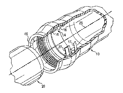
Figure 1 is a perspective view, partly broken away, of male and female pipe
sections
about to be made up into a pipe coupling, the belled end of the female pipe
section
showing one embodiment of the seal and restraint mechanism of the invention in
place
within a mating groove provided therein.
CA 02592669 2007-06-28
WO 2006/062884 PCT/US2005/043879
-6-
Figure 2A is a side, cross-sectional view of a portion of the female pipe
section showing
the seal and restraint system of Figure 1 in greater detail.
Figure 2B is a view similar to Figure 2A, but showing the beginning step of
inserting the
male pipe section within the female, belled pipe end, the male and female pipe
sections
being joined to form a secure connection.
Figures 3-6 are simplified, schematic views of the prior art Rieber process
used to form
the female belled pipe end.
Figure 7 is an enlarged, side cross-sectional view of the seal and restraint
system of the
invention showing certain aspects of the geometry thereof.
Figure 8 is an isolated view of the gripping insert which is received within
the
circumferential interior region of the housing in the restraint system of the
invention.
Figure 9 is a top view of the gripping insert of Figure 8 showing the slit in
the
circumference thereof and showing a removable spacer about to be fitted within
the gap.
Figure 10 is a side, partially schematic view of one version of a forming
mandrel used
with the seal and restraint system of the invention.
Figure 11 is a close-up view of a portion of the mandrel of Figure 10 showing
the
collapsible surfaces thereof.
Figure 12 is a side, cross-sectional view similar to Figure 2A, but showing an
alternate
ring shaped housing and gripping insert of the invention.
Figure 13 is an isolated cross-sectional view of the gripping insert of Figure
12.
Figure 14 is a top view of the gripping insert of Figure 12.
CA 02592669 2011-01-27
-7-
Best Mode for Carrying Out the Invention
Turning to Figure 1, there is shown an exploded view of a plastic pipe joint
in which a
belled female pipe end 10 is provided with an annular groove (shown as 12 in
Figure
2A) for receiving the seal and restraint mechanism 14 of the invention. The
improved
integral seal and restraint mechanism of the invention is capable of joining
and sealing
the female plastic pipe 10 to the spigot end of a mating male plastic pipe
section 20
having an exterior surface 29. The plastic pipe male and female ends 10, 20
can be
made from any convenient synthetic material including the polyolefins such as
polyethylene and polypropylene but are preferably made from polyvinyl chloride
(PVC).
As best seen in Figures 1, 2A and 2B, the seal and restraint mechanism 14
includes
an elastomeric, circumferential sealing ring 16 which is formed as an
elastomeric
body. The annular sealing ring 16 is somewhat tear drop shaped in cross
section and
includes a bulbous end region 28 (Figure 2A) and a thinner forward most region
30.
The bulbous end region 28 terminates in a nose portion 8. The sealing portion
also
has an exposed exterior region (generally at 32) which contacts the exterior
surface
29 (Figure 2B) of the mating male pipe section upon assembly of the joint. The
sealing
member is preferably made of a resilient elastomeric or thermoplastic
material. The
sealing member can be formed, for example, from natural or synthetic rubber,
such as
SBR, or other elastomeric materials which will be familiar to those skilled in
the plastic
pipe arts such as EPDM or nitrile rubber. In this case, the sealing ring 16
has a metal
reinforcing band 17 about the outer circumference thereof. However, as will be
apparent from the description which follows, any number of specialized sealing
rings
can be utilized in order to optimize the sealing and restraining actions of
the
assembly.
The seal and restraint system of the invention also includes a companion
restraint
mechanism for the sealing ring 16 which allows movement of the mating male
pipe
(20 in Figure 1) relative to the belled end of the female pipe 10 in a first
longitudinal
direction but which restrains movement in a second, opposite relative
direction. The
companion restraint mechanism includes a ring shaped housing 18 (Figure 2A)
having
a circumferential interior region 19 and an exterior 21. The ring shaped
housing
provides radial stability and reinforcement for the male (spigot) pipe end
during make
CA 02592669 2011-01-27
-8-
up of the joint so that the male pipe end 20 is radially supported and remains
perfectly
circular during the joint assembly process. The exterior 21 extends from a
nose region
22 (Figure 2B) in convex fashion, gradually flattening out into a planar back
region
which terminates in a tip region 24. The tip region 24 serves as a protective
skirt
which covers any gap between the sealing ring 16 and ring shaped housing 18
during
the pipe belling operation. Although the housing could have a circumferential
opening,
it is preferably provided as a solid ring of a slightly larger internal
diameter than the
forming mandrel (to be described) upon which it is received during pipe
belling
operations. Alternatively, the housing could be used with some form of
collapsible
forming mandrel, in which case its internal diameter might approach or exceed
that of
the mandrel in certain of its states of operation. The exterior 21 of the
housing 18 may
be equipped with one or more rows of gripping teeth 23 for engaging the
surrounding
pipe groove 12. The corresponding grooves or, indentations in the pipe
interior would
be formed during the belling operation as the pipe cools. The ring shaped
housing 18
is preferably formed of a material selected from the group consisting of
metals, alloys,
elastomers, polymeric plastics and composites and is rigid or semi-rigid in
nature.
The leading portion of the circumferential interior region 19 is sloped
upwardly with
respect to the longitudinal axis (25 in Figure 1) of the pipe. This leading
portion of the
circumferential interior region 19 forms an upwardly sloping ramp surface for
a
companion gripping insert 27. The sloping ramp surface extends upwardly from a
positive stop region (34 in Figure 2B) and gradually flattens into a planar
circumferential region which terminates in an internal shoulder (26 in Figure
2B)
arranged opposite an external shoulder 44. The positive stop region 34
prevents the
companion gripping insert 27 from overly compressing the 0. D. of the mating
male
pipe as the pipe joint is being assembled.
The housing external shoulder (44 in Figures 2A and 2B) is substantially
perpendicular to the longitudinal axis 25 of the female pipe. The external
shoulder 44
is in contact with the nose region of the elastomeric body of the sealing ring
16 as the
mating male pipe is inserted into the mouth opening (46 in Figure 1) of the
female
belled pipe end 10. The housing and sealing ring can be provided as separate
pieces,
as shown in Figures 2A and 2B, or can be at least temporarily joined at a
juncture
point prior to the pipe belling operation. For example, a suitable glue or
adhesive
could be used to form a temporary juncture at the external shoulder 44 of the
housing
CA 02592669 2011-10-05
-9-
18. In such case, the temporary juncture would typically be designed to be
severed
during the belling operation so that the sealing ring 16 and the housing 18
are
separate at the time a pipe joint is made up in a field application. The
housing 18
could also be integrated with the sealing ring 16, as during the curing of the
elastomeric body of the ring.
Figures 2A and 2B illustrate the positioning of the companion ring-shaped
gripping
insert 27 which is received in complimentary fashion and contained within the
circumferential interior region 19 of the housing 18. As shown in Figures 2A
and 2B,
the nose region 22 of the gripping insert 27 contacts the positive stop region
34 on the
I. D. of the housing 18 in the forward most position to thereby assist in
retaining the
gripping insert within the housing. The gripping insert 27 has an exterior
surface 31
(Figure 8) and an interior surface 33 with at least one row of gripping teeth
35. In the
embodiment of the invention shown in Figure 8, the gripping insert 27 has four
rows of
teeth 35, 37, 39 and 43. The rows of teeth are arranged for engaging selected
points
on the exterior surface 29 of the mating male pipe section 20.
The gripping insert exterior surface 31 has a sloping profile (42 in Figure 8)
which
contacts the upwardly sloping ramp surface (generally at 19 in Figure 2A) of
the
housing 18, whereby contact with the exterior surface of a mating male pipe
(20 in
Figure 2B) causes the gripping insert 27 to ride along the male pipe exterior
surface at
an angle while the row of gripping teeth on the gripping insert internal
surface engage
the exterior surface of the mating male pipe.
The rows of teeth 35, 37, 39, 43 on the lower surface 33 of the ring shaped
insert 27
can be of equal length or can vary in length and can be arranged in either a
uniform or
nonuniform pattern about the inner circumference of the gripping insert. The
teeth of
the gripping insert are also angled away from the horizontal axis of the joint
(25 in
Figure 7) at an angle "a" of less than 90 .
As best seen in Figure 9, the gripping insert has at least one slit 38 in the
circumference thereof which forms an opening of approximately 15 with respect
to
the central axis 39, as viewed in Figure 9, for the particular size insert in
question. The
gripping insert 27 is a rigid or relatively rigid member. By "relatively
rigid" is meant that
the gripping insert 27 can be formed of a hard metal, such as corrosion
resistant
CA 02592669 2011-01-27
-I0-
stainless steel, or from other metallic materials or alloys or even a hardened
plastic or
composite.
Figures 12-14 illustrate another version of the housing and gripping insert of
the
invention. The ring shaped housing 60 in Figure 12 again has a circumferential
interior
region 57 and an exterior 59. The exterior 59 extends from a nose region 61 in
convex
fashion, gradually flattening out into a planar back region which terminates
in a tip
region 63. Unlike the housing 18 shown in Figure 2A, the housing 60 of Figure
12 has
the rows of exterior teeth 65 all moved forward of a central vertical axis 67.
The
placement of the teeth 65 has been found to more effectively counteract the
opposing
force of the pressurized pipe in use which would otherwise tend to cause the
pipe joint
to be forced apart and to cause the restraint mechanism to be squeezed through
the
resulting gap. The space indicated generally at 69 in Figure 12 is intended to
illustrate
that the preferred gripping ring insert 71 is now dramatically smaller in
diameter than
the male spigot pipe end. This difference in ring diameter effectively means
that the
male spigot pipe end must expand the gripping ring insert 71 as the pipe joint
is being
assembled. As a result, there is some drag on the pipe exterior during
installation
which facilitates the biting and gripping action of the gripping insert teeth
73.
As shown in FIG. 12, the housing circumferential interior region 75 comprises
a ring-
shaped recess and again slopes upwardly with respect to the pipe longitudinal
axis
with the leading portion thereof forming an upwardly sloping ramp surface for
a
companion ring shaped gripping insert 71, whereby the gripping insert 71 is
contained
within the circumferential interior region of the housing in the ring-
receiving recess.
The sloping ramp surface extends upwardly from a positive stop region (77 in
Figure
12) and gradually flattens into a planar circumferential region which
terminates in an
internal shoulder 79 arranged opposite external shoulder 81. The positive stop
region
77 prevents the gripping insert ring 71 from tending to over-compress the
mating male
plastic pipe section during assembly of the pipe joint. As a result of the
interaction of
the gripping insert ring 71 and the stop region 77, there is no point loading
or pipe
distortion during assembly. While point loading may not be a significant
factor in
ductile iron systems, it can be a critical factor in ductile iron to plastic
systems.
Figure 13 illustrates the different geometry of the gripping ring insert 71.
As will be
apparent from the cross-section, the gripping insert 71 has a generally
rectangular
CA 02592669 2011-01-27
-11-
cross- sectional region 83 to the rear of a vertical axis 85 and a conically
shaped
cross-sectional leading region 87 forward of the axis 85. The 0. D. of the
insert 71 has
a sloping nose region 89 which joins a cylindrical outer surface 91. The
interior
circumference 88 has a plurality of rows of gripping teeth, such as row 93 in
Figure
13. In the embodiment of the device illustrated in Figure 13, the rows of
teeth are
evenly spaced and the height of the teeth (indicated as "h" in Figure 13) in
each row is
identical. As best seen in Figure 14, the gripping insert has at least one
slit 95 in the
circumference thereof which forms an opening of approximately 150 with respect
to
the central axis 97, for the particular size insert in question.
The modified design of the gripping insert 71 tends to concentrate the contact
force
during assembly of the pipe joint on the leading teeth (93 in Figure 13). As
the teeth
begin to sink into the exterior surface of the mating male pipe, the insert
tends to
recover its original posture, so that all of the rows of teeth tend to produce
the same
indentation. By using the ring geometry shown in Figure 13 and by increasing
the
interference between the ring and the male pipe (by decreasing the diameter of
the
gripping insert), contact force can be concentrated on the leading row of
teeth 93,
even where all the rows of teeth are of the same size or height. As a result,
once the
gripping portion of the restraint mechanism is activated, all of the teeth
have virtually
the same penetration into the male pipe.
Because the preferred restraint system of the invention utilizes two
components,
namely the sealing ring and the rigid gripper ring, the sealing ring can
actually serve to
pre-load or energize the gripper ring so that the ring is more firmly engaged
on the
exterior surface of the male pipe section. This can be accomplished, for
example, by
intentionally providing an excess amount of rubber in the sealing ring over
that
normally provided to perform the sealing function alone so that the sealing
ring bears
against the gripper ring and creates a positive loading effect.
Figures 1, 2A and 2B also illustrate the make-up of a joint of plastic pipe in
which the
male spigot end 20 is inserted within the belled female pipe section 10.
Figure 2B
illustrates the gripping action of the rows of teeth 35, 37, 39, 43 of the
gripping insert
in which the teeth grip the exterior surface 29 of the male pipe section 20.
The rows of
teeth 35, 37, 39, 43 are angled inwardly with respect to the axis 25 so that
contact
with the male pipe end (20 in Figure 2B) causes the teeth to be deflected in a
CA 02592669 2011-01-27
-12-
counterclockwise direction with respect to axis 25 during the insertion step,
as viewed
in Figure 2B. Once the male pipe section 20 has been fully inserted, the rows
of teeth
35, 37, 39, 43 grip the exterior surface of the male pipe and resist movement
in an
opposite longitudinal direction. The nose region 8 of the sealing ring 16 also
contacts
and forms a sealing region with respect to the external shoulder 44 of the
housing 18.
In order to explain the manufacturing process used to locate the seal and
restraint
system of the invention within the mating groove provided in the female pipe
end 10, it
is necessary to briefly explain the prior art "Rieber" process for plastic
pipe
manufacture. That was briefly described in the Background of the Invention. As
previously described, in the Rieber process, the elastomeric gasket was
installed
within a simultaneously formed internal groove in the socket end of the female
pipe
during the pipe belling process. The provision of a prestressed and anchored
elastomeric. gasket during the belling process at the pipe factory provided an
improved
socket end for a pipe joint with a sealing gasket which would not twist or
flip or
otherwise allow impurities to enter the sealing zones of the joint, thus
increasing the
reliability of the joint and decreasing the risk of leaks or possible failure
due to
abrasion.
While the Rieber process provided an integral sealing gasket which was
"prelocated"
within the belled, female pipe end in a groove which was formed about the
gasket, it
did not provide any mechanical "restraining function" to prevent separation of
the male
and female pipe ends at the pipe connection once the pipe joint was made up.
The relevance of the Rieber process to Applicant's invention can perhaps best
be
appreciated with reference to the description of the prior art process shown
in FIGS.
3-6. FIG. 3 shows a section of a conventional elastomeric sealing gasket 111
having a
steel reinforcing ring 113 in place on the generally cylindrical outer working
surface
115 of the mandrel 117 used in the belling process. The elastomeric gasket 111
can
be formed of, for example, SBR rubber and is a ring shaped, circumferential
member
having an inner compression surface 119 and an exposed nose portion 121 which,
as
shown in FIG. 3, abuts a forming collar 123. The forming collar 123 has a
first
generally cylindrical extent
CA 02592669 2011-01-27
-13-
125 which is joined to a second cylindrical extent 127 by a step region 129,
whereby
the second extent 127 is of greater external diameter than the first
cylindrical extent
125, shown in FIG. 3.
In the first step of the prior art process, the steel reinforced elastomeric
ring 111 is
thus placed onto the working surface of the mandrel 117 and pushed to a
position
against the back-up or forming collar 123. In this position, the gasket is
firmly
anchored to the mandrel surface with the rubber between the mandrel and the
steel-
ring of the gasket being compressed by approximately 20%.
In the second step of the prior art process, the socket end 133 of the
thermoplastic
pipe 131 is heated and pushed over the steel mandrel 117, gasket 111 and back-
up
collar 123. The socket end 133 is expanded due to the thermoplastic nature of
the
pipe. A number of thermoplastic materials, such as polyethylene, polypropylene
and
polyvinylchloride (PVC) are known in the prior art having the required
expansion
characteristics, depending upon the end application of the pipe joint.
However, the
preferred material for this application is PVC due to its expansion and
contraction
characteristics. The socket end 133 flows over the first cylindrical extent
125 of the
back-up collar 123 and abuts the step region 129 in the second step of the
process.
Note that the pipe end is deformed by the presence of the gasket 11 so that a
gasket
receiving groove is formed with the pipe I. D.
In the next step of the prior art process (FIG. 5) the mandrel and pipe move
away from
the back-up collar 123 and the pipe socket end 133 retracts around the mandrel
and
gasket 111 due to the elastic forces of the thermoplastic material. Typically,
vacuum
was also applied through ports 135, 137 which connected the mandrel working
surface with a vacuum source (not shown). In the final step of the prior art
process,
the pipe socket end 133 is cooled by means of a water spray bar 139 and spray
nozzles 141. As the cooling takes place, the pipe socket end 133 shrinks
around the
gasket 111, thus compressing the rubber body of the gasket between the steel
reinforcing ring 113 and the socket-groove to establish a firm seal. The above
described Rieber process has been in commercial use since the early 1970's and
is
described in the above referenced issued United States patents, among other
sources. It will thus be well familiar to those skilled in the thermoplastic
pipe sealing
arts.
CA 02592669 2011-01-27
-14-
Applicant's seal and restraint mechanism differs from the above described
Rieber
process in that the system of the invention serves to provide both sealing and
restraining functions. In the preferred embodiment, the system is comprised of
two
distinct components, the previously described sealing ring 16 and the housing
18 and
companion gripping insert 27, rather than a single elastomeric component.
The method of installing the components of the restraining system of the
invention will
now be described. In the preferred method of installation, the sealing ring
(16 in
Figure 2A) and ring shaped housing 18 are placed side by side on the forming
mandrel (such as mandrel 117 in Figure 3) and the female pipe end is heated
and
belled over these components in the normal fashion, as has been described with
respect to the Rieber process. The backup collar position or the mandrel
seating
groove location and size may have to be adjusted for the resulting changes in
bell
dimensions, i.e., to allow enough room for the housing 18. Once the belled
pipe end
has been cooled and the forming mandrel has been retracted, the gripping
insert 27
can be snapped or popped into position on the inner circumference of the
housing 18,
as shown in Figure 2A.
It may also be possible to bell the female pipe end over the housing 18 with
the
gripping insert ring 27 already in place on the inner circumference of the
housing 18.
For example, a removable spacer 41 in Figure 9 can be temporarily placed in
the
circumferential slit 38 in the circumference of the gripping insert 27 once
the insert has
been installed in the housing. In this way, the ring shaped insert is spread
apart an
additional, preselected amount once the insert is received within the
circumferential
interior region 19 of the housing 18. As a typical example, for a ring shaped
insert 27
in Figure 9 having an internal diameter of about 348 mm, the insertion of the
spacer
41 opens the 15 opening 38 out to about a 21 opening. At the same time, the
gripping insert 27 is pushed deeper into the interior region 19 of the housing
18. The
amount the gripping insert 27 is spaced apart is selected to cause the
gripping insert
to be initially received more closely within the housing circumferential
interior
regionl9, whereby the teeth 35 of the insert are initially concealed in the
housing
circumferential interior region 19. This placement of the spacer 41 in the
slit or
opening 38 helps to prevent the insert
CA 02592669 2007-06-28
WO 2006/062884 PCT/US2005/043879
-15-
from making detrimental contact with an exterior surface of a forming mandrel
during
subsequent belling operations.
Thus, it may be possible, in some circumstances, to bell the female pipe end
about the
seal and restraint system as described in Figures 3-6 by using the previously
described
removable spacer 41. However, because the seal and restraint system of the
invention
includes two component parts, namely the resilient sealing ring and the
companion rigid
housing and gripping insert, it may not be possible to easily slide the
companion
components over the belling mandrel exterior surface as in the traditional
"Rieber style"
manufacturing process. The presence of the rigid housing 18 may also
necessitate that
more specialized design features be incorporated into the forming mandrel,
such as the
use of a "collapsible mandrel."
Figures 10 and 11 illustrate, in simplified fashion, an alternative
installation operation in
which a working mandrel is provided with an outer, generally cylindrical
working surface
55 and collapsible elements 48. The components 16, 18 can be positioned on the
forming mandrel by temporarily collapsing the elements 48. Once the components
are
in position, the elements 48 are extended. After the heated pipe end is forced
over the
mandrel and expanded over the seal and restraint components 16, 18, the pipe
end is
cooled. The mandrel elements are collapsed inwardly by means of the actuating
mechanism 50 and the mandrel is then removed from the pipe. Figure 11 is
intended to
illustrate the relative movements of the mandrel elements 48, in simplified
fashion. Pipe
forming mandrels featuring collapsible elements are known generally by those
skilled in
the pipe forming arts. For example, see U.S. Patent No. 4, 239,473 for an
example of
a collapsible mandrel and U.S. Patent No. 4,643,658 for an example of a "ramp"
style
forming mandrel.
Because the pipe joints of the invention incorporate both a sealing member and
a
separate gripping member, they depart from the teaching of the prior art
Rieber belling
process. However, as in the Rieber manufacturing process described above, the
preferred seal and restraint mechanism of the invention is integrally belled
in the female
pipe end during manufacture of the bell end. Thus, the seal and restraint
mechanism of
the invention can be installed and prelocated within a mating pipe groove in
the "Rieber
CA 02592669 2007-06-28
WO 2006/062884 PCT/US2005/043879
-16-
style", with the exception that it may be necessary to use a "collapsible
mandrel" or a
"ramp" style mandrel to accommodate the housing orgripping insert which are
positioned
on the exterior of the forming mandrel in some circumstances. Also, while the
invention
has been described with reference to a single internal groove formed within
the female
bell pipe end, it will be understood that two or more grooves can be formed in
the bell
pipe end, either mechanically at the factory prior to installing the
restraining system
components, or in the Rieber fashion so that the grooves are simultaneously
formed
about the restraining system positioned on the forming mandrel.
An invention has been provided with several advantages. The present invention
provides
a sealing and restraint system in which the restraint mechanism is integral to
the groove
formed in the bell end opening of a female pipe member. The restraining
mechanism
may be provided as a part of a "gasket formed" bell groove, as in a Rieber
style pipe
belling operation where the groove is simultaneously formed as the bell pipe
end is
formed. In its most preferred form, the manufacturing method and device of the
invention provide an improved seal and restraint system for plastic pipe
joints utilizing the
"gasket formed" bell groove, which does not require assembly in the field and
which thus
simplifies installation of pipe sections at the pipe joints used to form a
fluid conveying
pipeline.
The integral restraint system of the invention eliminates the need for an
external
clamping device of the type presently used in the industry to achieve the
restraining
function, which device is totally separated from the sealing function. This
eliminates the
possibility of external corrosion of the metallic components of the prior art
external
restraints. The system of the invention is also simple in design, dependable
in operation,
and is less costly to manufacture than the prior art restraining systems which
utilize
external glands and mechanical restraint components.
Because the ring components of the restraint system of the invention are pre-
installed,
the possibility of mistakes during field assembly is virtually eliminated.
Also, the gripping
insert component of the invention applies more pressure to the exterior
surface of the
mating male spigot pipe end as internal pressure builds within the fluid
coupling. This
action helps to ensure the integrity of the joint. In addition, the gripping
ring component
CA 02592669 2007-06-28
WO 2006/062884 PCT/US2005/043879
-17-
aids in sealing the joint by keeping a constant gripping pressure on the male
pipe end at
even the lowest operating pressures of the pipeline.
While the invention has been shown in only one of its forms, it is not thus
limited but is
susceptible to various changes and modifications without departing from the
spirit
thereof.