Note: Descriptions are shown in the official language in which they were submitted.
CA 02592760 2007-07-04
REACTIVE PROTECTION ARRANGEMENT
BACKGROUND OF THE INVENTION
1. Field of the invention
The present invention concerns pyrotechnic protection and in
particular a fragment-free reactive protection arrangement in relation to
hollow charge threats.
2. Technical background
By virtue of their very high level of penetration power the anti-tank
defense hand weapons (ATDHW) equipped with a hollow charge warhead
represent a high level of threat in particular in relation to lightly or
medium-heavily armored vehicles. In that respect the Russian PG-7 in
out-of-area uses is increasingly proving to be a battlefield threat which is
basically to be taken into consideration as that weapon system is very
widespread on a world-wide basis.
Protection for light and also medium-heavily armored vehicles in
relation to anti-tank defense hand weapons of that nature is only very
limited or no longer possible, with conventional reactive and in particular
passive protection systems, because the useful load of the vehicles is
limited and the weight in relation to surface area of the armoring, which is
necessary for protection, is too high. The lighter vehicles have only thin
wall thicknesses as the basic vehicle protection is usually only designed in
relation to small-caliber armor-piercing munition of a caliber of up to 14.5
mm. Therefore, various protective systems which are reactive, that is to
say which act with explosive, have been developed in order to reduce the
weight in relation to surface area, which is required for such protection.
For example the hollow charge protection of medium-armored
vehicles with a basic protection of about 30-50 mm armor steel equivalent
with passive protection systems requires an additional weight in relation to
surface area of the order of magnitude of 500 kg/m2 and with previously
known reactive protection systems which are already powerful, it still
1
CA 02592760 2007-07-04
requires an additional weight in relation to surface area of the order of
magnitude of 300 kg/mz in relation to the threats presented by ATDHW.
Thus, since the beginning of the Seventies, both in relation to
hollow charges (HC threat) and also in relation to inertia projectiles (KE-
threat), arrangements are known in which pyrotechnically accelerated
elements provide for lateral disruption of the hitting or entering or
penetrating threat and thus a reduction in the penetration power. Upon
initiation by the impacting threat such arrangements are referred to as
reactive protection while in the case of controlled firing they are referred
to as active armoring. Reactive arrangements quite predominantly involve
single-layer or multi-layer covering, at one or both sides, of the explosive
with mostly metal plates. Arrangements of that kind, with suitable
dimensioning, are effective both in relation to hollow charges and also in
relation to KE projectiles and are in use on a world-wide basis as
protection modules in relation to many armored vehicles.
Reactive systems which accelerate plates suffer from the crucial
disadvantage that masses of greater or lesser size have to be accelerated
to speeds of more than 100 m/s, which stress both the surroundings and
also the structure carrying them. Therefore reactive armoring
arrangements are predominantly in the form of modules (surface
elements) of a building block nature. In the case of lighter objects to be
protected or when thinner structures are involved, the use of reactive
components is severely restricted or is not possible, precisely because of
the loading due to the system itself. That applies in particular in regard to
arrangements against KE threats as relatively large masses have to be
accelerated in order to reduce the power thereof. In the case of reactive
arrangements in relation to hollow charges, the required disruption
masses are admittedly considerably less, but in return very much higher
speeds are required in order still to reach the hollow charge blasts
impinging at up to 10 km/s, with laterally effective disruption masses.
2
CA 02592760 2007-07-04
Arrangements are also known which disrupt the hollow charge
blasts during penetration directly by means of explosive layers or by
electrical fields, deflect them and thus implement a reduction in power.
Arrangements of that kind, when using explosive, are linked to the use of
considerable explosive thicknesses in order to maintain blast-disrupting
conditions over a prolonged period of time (caused by the blast length to
be disrupted). Explosive layers admittedly fire very rapidly when hollow
charge blasts penetrate thereinto but nonetheless in the case of
conventional sandwich arrangements, even with a relatively large angle of
inclination in relation to the penetrating blast, they do not provide directed
lateral blast disruption, in particular in the front region. That is only
achieved if there is an inclined, virtually free explosive surface which is
possibly combined with a supporting (tamping) wall. Pure, comparatively
thick powder or explosive layers or explosive foils applied to a plate or wall
are used in a series of known arrangements. These basically involve
reactive arrangements of conventional configuration with an explosive
covering at one side.
Although detonation of the explosive takes place very quickly in the
case of hollow charges, nonetheless a certain period of time is required to
build up a pressure field as the penetrating particles cause the target
material involved to be initially mechanically accelerated in an
approximately hemispherical configuration away from the penetrating
blast tip. That firstly gives rise to a hollow space through which a more or
less large part of the tip region of the blast, which is particularly
effective
because it is very fast, can pass without being disrupted. That region
however is crucial in regard to the residual effect of the HC threat and
thus determines the degree of efficiency of the defense or the expenditure
required for reducing power.
Corresponding considerations apply in regard to covering the
explosive layer with plates which are to be accelerated. Not only do they
have to be accelerated by shock waves and gas forces, but they also have
3
CA 02592760 2007-07-04
to bridge over the crater formed by the blast tip in order to be able to
laterally reach the penetrating blast. The structure of the arrangement
and in particular the angle thereof with respect to the penetrating threat
are here the crucial parameters. In the case of a series of known
arrangements, the attempt is made, by means of multi-layer reactive
protection structures which are in part heavily inclined, to minimize the
above-described detrimental effects of crater formation. In general
however that results in structures with a great deal of explosive or
modules with a small effective protection surface area and of a structural
depth which is great in comparison with the surface area which is covered.
In addition that gives rise to negative edge influences and inadequate
overlaps. In addition there is an increase in the proportion of dead
masses causes by the structure involved. Such masses which do not
serve directly for affording protection power, in all previously known
reactive protection arrangements, represent a considerable proportion of
the required mass in relation to surface area and correspondingly reduce
the protection efficiency.
Reactive protection arrangements are also known which are
disposed in front of the structure to be protected and the aim of which is
to reduce the negative mechanical or terminal-ballistic accompanying
phenomena on the surrounding area, by means of suitable explosive
coverings. Such structures which are generally multi-layer and generally
also complex involve an operative procedural configuration, which is
difficult to understand and manage, in respect of the individual
components and the co-operation thereof. They have admittedly proven
to be definitely effective in relation to hollow charges, but basically they
are subject to the above-discussed limitations in terms of effect and
evaluation criteria.
Previously known powerful reactive protection systems cannot
provide a complete defense against the HC threat even by the use of
considerable masses in relation to surface area as only a given proportion
4
CA 02592760 2007-07-04
of the hollow charge blast can be influenced by the disruption measures.
Therefore usually between about 20 and 30 percent of the power of the
hollow charge munition is compensated as a residual power by the basic
armoring of the vehicle.
There are a series of disadvantages as a counterpart to the weight
advantages of reactive arrangements, over passive protection
arrangements. Thus conventional reactive protection systems act
predominantly on the basis of the principle of flying plates which on the
one hand severely endanger the area surrounding the armored vehicle
and which on the other hand impinge on the structure with the plate which
is flying towards the vehicle wall. That is an aspect of very great
significance, particularly in the case of more lightly armored vehicles.
A series of armoring arrangements of that nature are known. The
accelerated plates in that case preferably consist of steel, as described for
example in EP 0 379 080 A2. In accordance with that disclosure the
reactive protection is combined with an additional passive protection in
order to compensate for the part of the hollow charge blast which is not
sufficiently reduced by the reactive protection.
US-A-S 824 951 describes a reactive armoring arrangement in
which the inert plates surrounding the explosive comprise different
materials. The plate which is accelerated towards the hollow charge blast
is of glass while the plate which flies with the blast towards the vehicle to
be protected consists of steel. A hollow space is present behind the plate
flying with the blast in order not to disrupt the movement thereof for the
period of interaction with the hollow charge blast.
US-A-4 741 244 describes a reactive armoring arrangement in
which a hollow space is provided behind the plate which is flying towards
the vehicle. That disclosure provides that the protection action of the rear
plate is greater than the plate which is flying towards the blast. The
rearwardly flying plate of steel moves at very high speed so that a
5
CA 02592760 2007-07-04
correspondingly heavy basic protection must be mounted on the vehicle so
that the vehicle wall is not penetrated by parts of the reactive protection.
DE 37 29 211 C1 describes a reactive protection arrangement in
which inclinedly arranged sandwich structures in the vehicle direction are
combined with a layer-wise structure of explosive and brittle materials
such as for example glass. The structure is intended to act against the
front part of the hollow charge blast which, by virtue of the inertia of the
inert plate members, almost unimpededly penetrates the reactive
protection mounted in front thereof. The described arrangement also
involves a high level of loading due to the parts impacting against the
vehicle.
DE 199 56 297 C2 describes reactive protection in relation to hollow
charges, in which, in layers arranged inclinedly with respect to the
bombardment direction, explosive is covered on the bombardment side
over the surface thereof with disruption layers of fiber composite material
for avoiding hard fragments. At least one disruption layer is formed from
a high-strength fiber composite material in the form of a flat textile
structure comprising synthetic or renewable raw materials or a
combination thereof.
DE 199 56 197 A describes a conventional reactive armoring
arrangement in which only the usual metallic component, for avoiding
structural and surrounding area damage, is replaced by a non-metallic
plate (preferably of fiber composite material). The protection action in
relation to HC and KE threats is achieved by the acceleration of one or
more such plates, the reactive arrangement being disposed in a non-
metallic housing. The depicted function of an additional plate which is
referred as a buckling plate cannot be understood.
US-A-5 637 824 concerns a conventional reactive composite
armoring arrangement with an explosive layer and a metallic plate which
is accelerated in the direction of the threat. Due to detonation, in a
relatively thick, dynamically acting layer which follows the explosive layer
6
CA 02592760 2007-07-04
and which is supported rearwardly by means of a metallic plate, the HC
blast is reduced in respect of its power by blast disruption. The dynamic
effect of the intermediate layer can be enhanced by a layer introduced into
the active zone and by a further explosive layer in front of the rear
metallic plate. That arrangement is based on the effect, described in the
literature, of the so-called "crater collapse" (dynamic collapse effect).
Materials referred to for the production of that effect are practically all
liquid, metallic or non-metallic materials - of which most however do not
have any physical effect of that nature. The situation is also described,
wherein the front tamping or support is only formed by a non-metallic
protection layer, in which case then an increased thickness of explosive is
required to produce the internal pressure required for a dynamic effect.
After detonation of the first foil the structure again represents a
conventional reactive armoring with an explosive layer covered on both
sides. In addition both the surrounding area and also in particular the
structure are subjected to loadings and stress.
DE 37 29 211 C involves a conventional reactive sandwich
arrangement (metallic plate with an explosive intermediate layer) which is
embedded into hard foam in a particular fashion. That first active layer is
followed by an explosive layer with subsequent brittle body structure
(glass body) with separation layers of explosive. The whole complex
arrangement is disposed in a metallic housing. In principle therefore the
described arrangement represents a relatively thick pre-armoring with
inclinedly disposed reactive sandwich structure comprising explosive-
accelerated steel plates, the intermediate spaces being filled with hard
foam. The powerful blast tip which as is known passes practically without
disruption through arrangements of that kind is to be caught in the
following layer of a dynamically supported or tamped glass body structure.
WO-A-94/20811 also involves a conventional reactive arrangement
with two explosive layers which are inclined relative to each other and
which are covered on both sides, in a massive metallic housing. The
7
CA 02592760 2007-07-04
subject of the invention was not the conventional reactive sandwich
arrangement with metallically accelerated plates, which was presumed to
be known, but the way in which they are arranged in a massive housing.
That structure provides both protection from HC threats and also from KE
threats. Such structures are used in a series of armored vehicles of Soviet
origin.
A basic problem in terms of the reactive sandwich protection
arrangements, in particular in relation to KE threats, lies in the
initiatability
of the explosives used, when relatively thin covering layers are involved,
as are required for reasons of the required low level of energy density
because of the shock loadings on the protection or housing structures.
Therefore the aim of the arrangement described in DE 33 13 208 C is to
implement blast disruption comparable to that of the so-called crater
collapse, by means of a porous or foamed layer, which is introduced into a
conventional reactive armoring arrangement, with incorporated explosive
component. That layer is covered on both sides with metallic plates in
particular to afford protection in relation to KE threats and thus again
represents a reactive structure of conventional type.
DE 102 50 132 A concerns protection arrangements in relation to
blast-producing and projectile-forming mines, but not in relation to hollow
charges. In that case the protection effect is afforded by way of
containers with a filling agent comprising a liquid or a fluid medium.
Basically this involves a protection structure which admittedly acts
dynamically, but not a reactive arrangement for defense in respect of HC
threats.
It can be deduced from the above-outlined description relating to
the state of the art for reactive protection systems that the previously
known reactive systems are still relatively heavy and require a
comparatively high level of basic protection to compensate for the residual
power. In the case of ATDHW this still corresponds to a required basic
8
CA 02592760 2007-07-04
protection of the order of magnitude of between 60 and 80 mm armor
steel equivalent.
SUMMARY OF THE INVENTION
The object of the invention is to also protect medium-heavily and
even only lightly armored vehicles with correspondingly slight basic
protection in relation to hollow charges, in particular in relation to
medium-caliber hollow charge projectiles such as for example PG-7,
without in that respect involving additional, ballistically operative
fragments. HC protection of that kind for lightly armored vehicles
requires:
- a very high level of effectiveness in respect of the protection
arrangement, a low weight in relation to surface area with at the same
time minimum residual power;
- the vehicle wall is not to be unacceptably heavily loaded or
penetrated either by the threat or by parts of the protection system;
- there is not to be any fragment loading in the area around the
vehicle by virtue of the protection system;
- the mobility of the vehicle is not to be limited, possibly it must be
possible to fit or remove parts of the protection system during a mission;
- the respective on-road authorization regulations (for example in
Germany the "Strassenverkehrs-Zulassungsordnung", abbreviated to
StVZO) must be complied with;
- there is not to be any danger going beyond the protection system
due to the explosive on the vehicle, that is to say in Germany for example
Classification 1.4 in accordance with the Hazardous Materials Regulations
("Gefahrgutverordnung", abbreviated to GGVS); and
- when the protection is mounted, rapid access to hatches and
stowage spaces must be possible.
In accordance with the present invention that object is attained in
that at least two layers of a pyrotechnic material of the same or also
different quantitative relationships and/or thicknesses are arranged at a
9
CA 02592760 2012-01-11
31416-2
spacing from each other freely or in a housing of a non-metallic material such
as for
example rubber at an angle to the bombardment direction. Advantageous
configurations and developments of the invention are subject-matter of the
appendant claims.
In a preferred configuration that pyrotechnic protection structure
comprises a carrier of any desired configuration which is inclined in the
impact region
or region of action of the threat and to which pyrotechnic layers are mounted
on both
sides. Due to firing of those layers shock waves and reaction gases are formed
and
accelerated both in opposite relationship to the direction of the penetrating
threat and
also in the direction thereof. In that way, in relation to hollow charges,
both the front
powerful blast elements and also a decisive part of the total blast length are
disrupted
and thus lose their penetration power. The pyrotechnic structure in that case
is
disposed over the entire period of action at least approximately in a
condition of
dynamic equilibrium and does not exert on its surroundings any influences
which are
destructive or relevant in terminal-ballistic terms, that is to say either on
the outside
region or on the structure itself which is to be protected. In that respect
the size of
the required presented region is afforded on the basis of simple kinematic
considerations in respect of the penetration process.
According to another aspect there is provided a reactive protection
arrangement without fragment formation being relevant in terms of terminal
ballistics
in both operational directions for an object to be protected, wherein two
pyrotechnic
layers which are inclined in the region of action of the threat are arranged
at a
spacing from each other and are arranged on both sides on a rigid or flexible,
single-layer or multi-layer carrier being inclined in the region of action of
the threat
and being formed of at least one metallic or non-metallic materials of very
low density
CA 02592760 2012-01-11
31416-2
of less than about 30 kg/m3, such that after firing of the two pyrotechnic
layers shock
waves and reaction gases are formed and are accelerated at an angle both in
opposite relationship to and also in the direction of the penetrating threat
in such a
way that the pyrotechnic protection surface made of the two pyrotechnic layers
and
the carrier is disposed almost over the entire period of action in a condition
of
dynamic equilibrium.
This involves a very simple and basic arrangement which fundamentally
is not subject to any limitations or restricting technical factors. Derived
therefrom is a
level of innovation which is not achieved by any previously known reactive
arrangement. In addition the pyrotechnic protection surface presented is
suitable for
affording a great increase in the level of protection in relation to a series
of known
armoring arrangements, both by virtue of being disposed in a frontal position
in
relation thereto and also by integration.
Basically pyrotechnic protection surfaces can be easily combined with
arrangements for defense against KE threats. At any event, no or
10a
CA 02592760 2007-07-04
only very small dead masses are required in regard to protection
optimization in relation to a number of kinds of threat.
It will be appreciated that, in spite of the basically unrestricted
freedom in terms of design configuration, a reasonable relationship in
respect of the few parameters involved must be observed. In the case of
conventional reactive armoring arrangements, the effectiveness is crucially
dependent on dimensioning factors. In contrast in the present invention
basically only a few prerequisites are to be observed, which in addition still
apply in regard to all reactive arrangements. These include for example
the minimum explosive thickness for ensuring initiation or on-going
detonation. An exception is formed by the desired deflagration, insofar as
that should not be attained by way of the composition of the pyrotechnic
layer. Further prerequisites arise out of the geometrical conditions and
the relationship between threat and protection surface dimensioning. In
that respect the materials used such as for example the nature of the
explosive or corresponding additions, up to the number of the protection
surfaces, are to be taken into consideration.
By virtue of the high level of effectiveness, with a pyrotechnic
protection surface in accordance with the invention, the explosive mass to
be employed per unit of surface area can be considerably less than in
comparison with previously known reactive armorings, as far as 50% if the
above-indicated limitations are observed. As an indicative value in regard
to that structure, the thickness of the explosive coverings, with an angle
between the defense region and the threat of over 30 , can be about 50%
of the mean blast diameter.
Fundamental considerations regarding the speeds which can be
achieved in relation to free and covered explosive surfaces can be set
forth by way of the Gurney equation for flat pyrotechnic surfaces:
vl = (2.E) .5 . ((1-A+A2)/3 + b-A2 + a)- 5
with a = M1/C and b = M2/C and A = (1 + 2*a)/(1 + 2*b);
M/C: ratio of the mass of wall and explosive;
11
CA 02592760 2007-07-04
index 1: front surface, index 2: rear surface;
(2-E) .5: Gurney factor (here assumed as 2,800 m/s);
v2 = A'vl.
In the case of a virtually single-sided covering a or b becomes equal
to zero.
The following Table calculates some dimensions which emphasize
the fundamental considerations involved. In this respect the important
consideration is not the absolute value but the clearly apparent
confirmations of the consideration in connection with the present invention
(D: thickness, M: mass, S: sandwich).
12
CA 02592760 2007-07-04
M 00 .-i m CO 00 N N CO
00 00 m 00 m Ln -4 ri N N 00 It N t0 .D
N 00 00 m 00 +-i c 'ri- Ln d' r-I It M Ln O O
> E M -I m M -1 0 m N Ln M M 't M N
M 00 .--I M 00 to m 194- N +-I lq- 0 0) N N 00
N 00 00 m 00 M 0) O O It +-i 0 It I- N / 0
.-i co 00 M 00 +-i N N N M M t0 In O O
> E m r-i m m It N M M m M It N 11, M N
O O O O O O .-i +-I N N N CO O O O O
O O O O O N N r-i O O O O .--I O O O
. . . . . . . . . . . . . .
< -I O O O O O O O
O O
O~ M O~ m k0 Ln M N N O c M In Ln
O O *-I O O N N Ln In Ln O N N
.-1 O O O O O O M N +--I Ln ~O 0 0 O O O
M c l0 N N N N N N N Ln m Ln Ln
O c ri O O M M M M M O O t0 O N N
. . . . . . . . . .
(6 +--I O O 0 0 O 0 0 O O O O 0 O O O O
N N M l0 N Ln M E O 0 O 0 0 M 0 ^ O O O N d> O t0
J
cn l0 l0 l0 l0 ,--I ri N ri L() Ln N Ln
,C r-i r-i .-I ri ,-I N l0 ri ri 00 r-4 +-I ri O 00 N
N
E N 0 l0 t0 N Ln
Ln 0) 00 [t - 't d' r-i m N m o Ln M
O 00 CO 00 06 ri M l0 CO N CO M 0 ra
N O
E 0 0 O Ln Ln Ln
N M 00 00 O O 0 N Ln In
0) 00 l0 N CO 00 CO
O N N N N Ln N Ln 00 Ct N N N O .-a
M
M
N E Ln Ln Ln
0 0 00 00 co CO co 00 00 00 00 00 00 00 00 Ln Ln Ln
i 0)0) N N N N N N N N N N r l%' N
ri ri
N O N
E
O O O O O O r-i N M O O O
N
E O O O O O O
U cn O O Ln Ln Ln Ln Ln Uf Ln N N N O O O
~C M M ,i M N N N N N ri ri ri l0 110 0
M
U E
0 0 Li) Ln Ln m Ln Ln Ln Ln Ln Ln N N N N N N
- 0) ri .-i ri ri v-1 .-i r-i r-i r-i ri r-i ,-i .-i .- .-i ri
U E N N Ln Ln Ln Ln Ln Ln Ln Ln
0 v 0 O +-i N M 0 O 0 O 0 ri ri ri 0 O 0
N
E
{ M 00 00 O 00 O CO OJ O co M co 0n N LP) Ln
- O N N N N N N N N N 0 '0N O +-i c
M
r-i E Ln Ln
0 0 00 00 O 00 00 00 00 00 00 00 00 00 00 Ln Ln Ln
0) N N N N N N N N N N N t~ t~ +-I . i d
ri ri ri O ri O O
E Q rI r-( r-I r-I rI rI rI ri .-i 0 0 .-i 0 .-I .-i
U O 0 O O 6 O O 6 6 6 6 6 O O O O
CA 02592760 2007-07-04
With a relatively great thickness of explosive (DC) and a relatively
thin carrier layer, the result is theoretical speeds of the order of
magnitude in respect of the blast speed of up to over 4 km/s. The free
surface or a slight covering in respect of the explosive surface decides on
an approximation to the theoretically attainable speeds.
When very thin coatings are involved (protection of the foil surface)
of the order of magnitude of 0.1 mm, very high surface speeds (over 3
km/s) are achieved, even with very thin explosive foil thicknesses (for
example 2 mm - the minimum thickness is determined by the firing
properties). The surface speed already falls to below 2 km/s with
coverings which are still very thin (for example 1 mm Al). It is however
still very high in comparison with conventional sandwiches.
In a situation involving single-sided or virtually single-sided
covering, average explosive thickness and relatively massive wall (for
example for KE protection or for system reasons), wall speeds of the order
of magnitude of only 50 m/s are afforded when realistic dimensionings and
very high single-sided speed are involved. Such low speeds are still to be
controlled with mechanical means. Accordingly, for this limit region of
constructions according to the invention, there are particularly attractive
combinations in which a high level of protection efficiency is combined with
a very small structural depth and without burdening the surrounding area
and structure.
The following fundament arrangements are considered by way of
example in connection with configurations of the carrier in accordance with
the present invention (see Figure 4 and Figure 5):
Figure 4A: symmetrical covering by means of pure explosive foils.
It will be appreciated that this also includes foils with surface treatment or
surface protection. This results in detonation which is simultaneous in a
first approximation. The "dynamic tamping" due to the detonation gases
increases the effective tamping mass and the result is a maximum surface
14
CA 02592760 2007-07-04
speed of the order of magnitude of the blast speed. The wall itself, by
definition, does not experience any acceleration. The speed of the
reaction gases can be considerably influenced by the foil configuration and
the explosive selected, and likewise by substances introduced into the
explosive matrix. When the explosive layer is covered with a massive
layer, as is quite predominantly the case in conventional sandwich
structures, that influencing option is severely limited.
Figures 4B and 4C: differing explosive covering. This affords a
resulting speed in respect of the separating wall or the carrier
respectively. With a suitable configuration and an appropriate choice of
material, this basically does not signify any limitation in terms of the use
bandwidth. Almost complete symmetry of the overall reactive
arrangement is then to be achieved by a symmetrical arrangement of two
surfaces. In a first approximation, the difference between the two
explosive foils can apply as the starting point for roughly estimating the
resulting acceleration of the carrying layer or the connecting layer, either
in the direction of the threat or in the opposite direction to the threat.
Figure 5A: disposed between the pure explosive foils is a more
expanded wall (for example of very low density of the order of magnitude
of 0.1 g/cm3). That wall can also be of a dynamically relatively hard
nature, with high compressibility.
Figures 5B and 5C: the explosive foils in the structure
corresponding to Figure 5A are covered either on the wall side (carrier
side) or on the outward side (threat and object side) by a very thin layer.
In accordance with the foregoing Gurney considerations, that permits
adjustment of the desired blast propagation speed on that side. Thus for
example it is also possible in the range of small surface coverings to attain
a prolongation of the duration of engagement in relation to the threat.
It will be appreciated that the explosive foils or also the coverings
may be of variable thicknesses. In that way for example it is possible to
CA 02592760 2007-07-04
influence the effectiveness of a surface portion, for example to
compensate for different protection depths or presentation angles.
In connection with capturing the fast blast portions due to
sufficiently high speeds in respect of free foil surfaces, arrangements
which act very widely over the inclined surface coatings, with a high
overall level of efficiency, can be afforded. A single-sided covering on the
explosive foil with an accelerated plate of conventional dimensioning can
then be considered as a limit case. That applies however only for that
partial component of a reactive structure but not for a reactive
arrangement in the sense of and as set forth in the claim of the present
invention.
A thicker carrying layer or a separation layer between the explosive
foils with additional physical properties, for example in respect of dynamic
behavior or specific properties in relation to shock waves, can be of
advantage if the depth of engagement is increased, that is to say a
plurality of blast particles or a greater blast length remains involved there.
Known glass bodies which are dynamically compacted by means of
explosive operate on that basis. Not least because of the required
thicknesses, in terms of the mass balance of an armoring arrangement,
they are however relatively heavy.
In the case of reactive armoring arrangements, the influence of the
size of the elements on the tamping effect and thus on the speeds which
can be achieved by the accelerated components is of great significance.
In that respect it can be readily seen that small element sizes and
relatively large explosive thicknesses as well as relatively high element
masses have a speed-reducing effect. For, the speed of an element of
small surface area is correspondingly reduced, the thicker (increased
mass) the covering is, and the thicker the explosive layer is. That
reduction in speed can be of the order of magnitude of 50% so that this
influence can greatly override other target-specific parameters. When
very small covering masses are involved or when pure explosive layers are
16
CA 02592760 2007-07-04
involved, that influence of the element size becomes correspondingly less.
In a first approximation it remains without influence on the speed of the
gas blasts. That affords a further advantage in arrangements in
accordance with the present invention. In particular the very important
design criteria such as module size and action in edge zones are positively
influenced.
A multi-layer structure for the carrier provides that the latter can
also serve as a control element for energy and signal transfer between the
explosive foils. A design criterion in that respect is the acoustic
impedance of the materials used.
The explosive layers required in pyrotechnic protection surfaces in
accordance with the invention make only slight demands in terms of
manufacturing tolerances and surface quality and thus the manufacturing
processes. That considerably increases the freedom in terms of the
design configuration of the surface of a protection element.
A further improvement is afforded by the basically known process of
covering the surfaces of the pyrotechnic layers with materials of differing
density. Advantageously, for those coverings, materials of low or higher
density, brittle, decomposing or delaminating materials such as glass,
composite materials, ceramics or materials which are shock-hard but
which are soft at relatively low deformation speeds such as for example
rubber are employed here, which with their high inertia, after a
comparatively long response time, dissipate or erode the middle and rear
part of the hollow charge blast, over a prolonged period of time. Suitable
materials of low density are for example metallic or non-metallic foams.
In the case of free explosive surfaces, air as the surrounding medium,
because of its low level of inertia, achieves a short response time and very
high acceleration for dissipating the fast parts from the front region of the
hollow charge blast.
Geometrical alterations can be made within wide limits by virtue of
application of the model rules used in ballistics, in particular the Cranz
17
CA 02592760 2007-07-04
model law which was originally formulated for the detonation of explosives
and later expanded to the whole of terminal ballistics. In that way a
structure which is tried and tested in practice can be transferred in very
wide limits to comparable uses by means of physical and geometrical
representational rules. Further aids in regard to dimensioning are
afforded by numerical simulations.
The high level of effectiveness of an arrangement according to the
invention is basically not linked to a housing. A container, housing or
covers serve primarily for fixing or protecting the active layers, also in
conjunction with protection components to be combined and in relation to
external influences.
In practice it is advantageous for the mode of operation of the
protection arrangement according to the invention to be linked to
structural factors in respect of the object to be protected. That can
extend from simply stringing them together to mutually supplemental
protection structures. The inert materials of the front and/or rear side of
the housing comprising one or more layers can also be optimized in terms
of the effectiveness in relation to KE projectiles.
In a preferred embodiment the layers of explosive and inert
materials are introduced into prefabricated pockets in the protection
module, whereby the reactive protection can be adapted to the vehicle to
be protected, in a simple manner which is readily appropriate for
manufacture.
BRIEF DESCRIPTION OF THE DRAWINGS
The Figures characterizing the invention and the description of the
processes involved in relation to impacting and penetrating threats are set
forth in the following list:
Figure 1 shows the basic structure of a pyrotechnic protection
surface according to the invention,
18
CA 02592760 2007-07-04
Figure 2 shows the mode of operation of the pyrotechnic protection
surface shown in Figure 1 at a relatively early moment in the entry and
penetration process,
Figure 3 shows the mode of operation of the pyrotechnic protection
surface shown in Figure 1 at a later moment in the entry and penetration
process,
Figure 4 shows examples of pyrotechnic protection surfaces as
shown in Figure 1 with thin carriers,
Figure 5 shows examples of pyrotechnic protection surfaces as
shown in Figure 1 with expanded carriers,
Figure 6 shows an example of a pyrotechnic arrangement with two
free explosive layers,
Figure 7 shows an example of a pyrotechnic arrangement with inner
tamping,
Figure 8 shows a further example of a pyrotechnic arrangement
with a buckling sandwich,
Figure 9 shows an example of a pyrotechnic arrangement with a
container/housing,
Figure 10 shows a further example of a pyrotechnic arrangement
with container/housing, and
Figure 11 shows a further example of a pyrotechnic arrangement
with container/housing.
DETAILED DESCRIPTION OF THE EMBODIMENTS PREFERRED AT THE
PRESENT TIME
The foregoing and further features and advantages of the invention
will be better appreciated from the description hereinafter of preferred,
non-limiting examples with reference to the accompanying drawings.
Thus Figure 1 shows the basic structure of a pyrotechnic protection
surface corresponding to the invention with the impacting hollow charge
blast or the impacting threat 1, the pyrotechnic coverings 2 and 3 and the
carrier 4 therebetween.
19
CA 02592760 2007-07-04
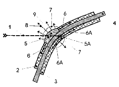
Figure 2 shows the condition or the mode of operation of the
pyrotechnic protection surface of Figure 1 at a relatively early moment in
the entry and penetration process. The initiation of the front (towards the
threat) pyrotechnic covering 2 is effected at the impact point of 1 against
2 (small circle 5). The detonation front is propagated in 2 at a speed
which is of the order of magnitude of the mean blast penetration speed in
the part of the hollow charge blast which is to be defended against
(symbolized by the arrows 6). In the case of a relatively thin carrier
initiation is effected in the rear pyrotechnic covering 3 both by the shock
waves which are propagated in a hemispherical configuration from 5 and
also by the penetrating blast tip at the impact point of 1 against 3 (small
circle 5A). The same conditions as in respect of 2 apply in respect of the
propagation of the detonation front in 3 (arrows 6A). By virtue of the
geometrical conditions and in particular also the configuration of 4, there
can be an asymmetry in the control space applicable in respect of the
moment in time being considered (large circle 7) for the play of forces and
thus the overall dynamics. That however has no influence on the
fundamental properties of the described arrangement. The detonation
fronts which are propagated against the threat, consisting of accelerated
reaction gases (and possibly accelerated surface layers), are symbolically
indicated by the expanding pressure field 9.
In the case of free or only slightly covered surfaces of 2 and 3,
there are high propagation speeds in respect of the detonation front and
the reaction gases in the direction of the entering and penetrating blast
(arrow array 8). The speed is also quite crucially increased by the
tamping property of the surfaces 4 and 3 (prior to firing statically by virtue
of the inertial mass, after firing of 3 by virtue of the pressure field which
is
formed), in relation to the explosive layer 2. As a result blast portions in
the tip region are laterally loaded and thus deflected or destroyed. In the
case of the hollow charge particles which are very sensitive to disruptions
in particular in the tip region, it is sufficient for them to be acted upon
with
CA 02592760 2007-07-04
a low level of energy for a great reduction in power (destruction) of those
parts.
By virtue of the above-described penetration mechanism however
the foremost parts of the blast still pass through the front pyrotechnic
layer 2. They are caught in the rear pyrotechnic covering 3. Because of
the currently prevailing physical conditions which apply there, the
geometrical relationships and the speeds which occur, in conjunction with
the short reaction times, the foremost blast tip is also reached in the rear
zone, so that overall the situation involves total loading on, deflection and
thus destruction of a large part of the hollow charge blast including the
foremost particles thereof.
Those conditions are shown in Figure 3. A part of the pyrotechnic
covering 2 has already been converted into a pressure field 9A which is
spreading out further. The control space for the overall dynamics,
symbolized by the large circle 8A, with the corresponding arrays of arrows
8 and 10, of the reaction surfaces of 2 and 3, shows both an overall
picture of the forces, which is compensated to a good degree of
approximation, and also the loading applied to the foremost blast tip in the
region, identified by a smaller circle 11, of the disruption field 12 formed
by 3.
Figure 4 shows examples of symmetrical or asymmetrical
pyrotechnic protection surfaces with carriers positioned therebetween.
They can be both protection-relevant (for example as KE protection or
protection against shallow cone charges) or of an extremely light nature.
Corresponding reactive arrangements can be formed from a single
element (flat or curved or any shape) or can be assembled to form a
surface by the combination of two or more elements. In that way it is
possible to adapt the reactive protection according to the invention to the
threat.
Figure 5 shows some examples of pyrotechnic protection surfaces
(here arranged symmetrically) with expanded carriers or inside surfaces
21
CA 02592760 2007-07-04
4A, 4B, 4C. As described, they can comprise extremely light materials or
they can also serve at the same time as internal volumes (for example as
containers) for other functions. It will be appreciated that no limits
whatsoever are set on the configuration of those inner regions, provided
that the mode of operation of the reactive components is not unacceptably
limited.
As shown by means of structures set forth by way of example (see
Figures 6 through 11) and experiments which have been conducted,
single-sided and/or double-sided coverings on the explosive surfaces in
the inner and/or outer regions 13, 13A, 14, 14A are of great significance
in particular for the overall efficiency of an armoring arrangement, and
equally for distribution of the protection that is still required, in relation
to
the residual penetration depth of the threat.
For an optimum protection effect in regard to reactive
arrangements according to the invention, single-sided or double-sided
support for one of the explosive layers can be advantageous in terms of
the overall balance sheet of the protection action or in connection with
factors relating to design technology. Such a support for the explosive for
enhancing the overall protection effect is advantageously implemented
with dissipating masses such as for example surfaces of metallic or non-
metallic foils, GRP, ceramic or glass or also fluids and gels.
In accordance with the foregoing description the materials of the
support and tamping means are advantageously to be so selected in
respect of amount and density that, in combination with the pyrotechnic
layers, one or more of the support or tamping layers is set in motion as
early as possible in order to destroy the front fast parts of the hollow
charge blast, and one or more support or tamping materials are set in
motion more slowly so that they can destroy the slower middle and rear
regions of the hollow charge blast.
22
CA 02592760 2007-07-04
The explosive layers can be embedded in one or more metallic or
non-metallic materials of low density (15-30 kg/m3) and high
compressibility as a matrix (see Figure 6).
The configuration of the carrier 4 is completely free. It is therefore
illustrated in Figure 1 in the form of a curved surface. All that is required
is a sufficient inclination relative to the threat in the region of action. By
virtue of the high efficiency of the pyrotechnic covering, in the
arrangement proposed herein, the minimum angle is by between 100 and
less in comparison with known reactive structures. As the basic
10 starting point in the case of sandwiches of a conventional kind is a
minimum angle of inclination of 45 , a mean angle between threat and
defense of between 30 and 40 is sufficient with the present
arrangement. The angle between the defense surface and the threat can
be formed by way of the angle of presentation of the total surface or by
15 way of geometrical modifications, by means of technical or structural
measures. Thus for example even in the case of a surface which is
inclined too little in relation to a threat for it to have a sufficient
action, the
required inclination can be achieved for example by corrugation, providing
an angled configuration or by laminating. In that respect the different
embodiments of the pyrotechnic protection surface can form a coherent
and continuous surface or can be made up from individual modules with
intermediate spaces or other separations (for example surface segments,
a Venetian blind-like arrangement, separate modules or modules which
engage into each other).
The technical configuration of the carrier is basically not subjected
to any limitations (for example metallic, non-metallic, structured, single-
layered or multi-layered). The carrier can be rigid or deformable/movable
and its thickness can extend from a foil thickness up to a massive plate or
thicker structure. It can also comprise an inert material or a
chemically/pyrotechnically reactive substance. Accordingly an inner high-
23
CA 02592760 2007-07-04
pressure field can also be built up in that carrier by the detonation of the
pyrotechnic coverings.
The powerfulness and efficiency of a protection arrangement is
generally assessed as the ratio of the reference mass (power of the
munition in armor steel equivalent) to the mass of the protection
arrangement itself, by means of two factors:
1. Em-factor, formed from: Em = mref/(mS + mRL), with mref as the
power of the threat in steel-equivalent mass, mS as the protection
mass used and mRL as the residual power in steel-equivalent mass;
and
2. Fm-factor, formed from Fm = (mref - mRL)/mS.
The Em-factor serves as an assessment scale for the quality of an
overall protection. In the case of a partial protection measure, that is to
say when there is residual power still present, assessment of the individual
protection arrangements is more meaningfully effected by way of the Fm-
factor in order to be able to comparatively assess the quality thereof.
The Fm-values which can be achieved in accordance with the
present state of the art, for passive protection arrangements, are in the
region of 5, while for reactive arrangements they are in the region of
between 8 and 10.
An arrangement according to the invention basically presupposes
the use of pyrotechnic substances with a dynamics corresponding to the
situation of use, that is to say reactivity. Handling of the pyrotechnic
elements required here and the safety precautions related thereto and
other operational factors are decisively improved insofar as the necessary
technical requirements for the carrier structure and the vehicle
respectively can be set at an extremely low level by virtue of the
described advantages. In addition the period of use of an effective
pyrotechnic covering can be minimized by suitable precautions.
Figure 6 shows a structure in principle, corresponding to Figure 5A.
The hollow charge is positioned at a spacing 15 from the reactive
24
CA 02592760 2007-07-04
protection arrangement. The latter in the simplest form comprises the
explosive layers 16 and 17 which are inclined with respect to the blast axis
1. The layers 18, 19 and 20 serve for purely fixing the explosive layers 16
and 17. Those layers 18, 19 and 20 can also serve as very light tamping
and support means. In that respect the required propagation speed of the
surface however may not be substantially limited.
The protection arrangement corresponding to Figure 6 was
experimentally tested at 45 with an experimental charge of type PG-7 at
a spacing (15) of about 2.5 calibers. The protection structure consisted of
foam/explosive/foam/explosive/foam, and the weight in relation to surface
area, with a density of the foam of about 15 kg/m3, was less than 30
kg/m2 in LoS (line of sight). The experimentally ascertained residual
power was about 30% of the power of the hollow charge in armor steel.
An extremely high Fm-value of over 70 is calculated therefrom. In
addition, as in the following examples, terminally ballistically relevant
parts are not produced either in the direction of the threat or in the
direction of the object to be protected.
That confirmed that such an extremely light arrangement according
to the invention is suitable as general protection in conjunction with
objects to be protected generally, as additional armoring and in particular
as protection for almost all vehicles. Such an arrangement is also best
suited for vehicles with a high level of basic protection, in particular
combat tanks, in order to protect the side and the tail from a threat by an
ATDHW.
In a further experiment the front explosive layer 16 was covered
with a relatively thin layer of a material of medium density. With a weight
in relation to surface area of the reactive protection arrangement of about
100 kg/m2, the residual power was only about 10%. That gives an Fm-
value of over 25.
If those experimentally ascertained power values are compared to
values of known reactive protection arrangements, the difference in
CA 02592760 2007-07-04
relation to the protection arrangement according to the invention becomes
clear, both in respect of residual power (10% in comparison with about
30%) and also weight in relation to surface area (N 100 kg/m2 in
comparison with 300 kg/m2).
In a further test both the front explosive layer 16 and also the rear
explosive layer 17 were tamped on the side of the carrier with a brittle
material of medium density (20, 20A) (Figure 7). By virtue of the
relatively thin inner layer of foam 19, this involves a particularly shallow
protection structure as shown in Figure 5B. With a weight in relation to
surface area of the reactive protection arrangement of below 90 kg/m2,
the residual power was less than 10%. That gives an Fm-value of over
30.
The residual power of the hollow charge must be compensated by
ballistically active materials. As even materials such as armor steel, high-
strength duralumin or titanium only achieve effectiveness levels of up to
1.5, the particular powerfulness of this protection arrangement according
to the invention becomes clear, in particular in consideration of the use in
relation to light systems. The extremely low levels of residual power
achieved confirm that the use of such a reactive protection arrangement
according to the invention is a possibility for medium and even lightly
armored vehicles.
This was confirmed by an experiment with a reactive protection
arrangement as shown in Figure 8. In that combination of the
arrangements shown in Figures 5 and 6 (front covering: thin layer 21 of
medium density), a buckling device 22 was arranged on the target side
after an explosive layer 17 embedded in foam 19, 20. With a weight in
relation to surface area of the overall protection arrangement of about 170
kg/m2 the residual power was only between about 1% and 2%.
A comparison of the absolute values of the reactive protection
arrangement according to the invention with reactive protection systems
according to the state of the art clearly shows this significant level of
26
CA 02592760 2007-07-04
innovation. Conventional reactive protection systems with a weight in
relation to surface area of 300 kg/m2, in the best case, achieve residual
power values of 20% of the reference power of the threat, that is to say in
the case of a threat due to an ATDHW with a power of between 300 mm
and 400 mm armor steel equivalent, they give a residual power of
between 60 mm and 80 mm armor steel. That corresponds to a weight in
relation to surface area of between 480 kg/m2 and 640 kg/m2. In the
most favorable case therefore the arrangement involves a total weight in
relation to surface area for the required armor protection of 780 kg/m2. If
the area to be protected of an object is for example 6 m2 (for example
side protection), then a total protection weight of 4680 kg is required. In
comparison the residual power of the reactive protection arrangement
according to the invention is only at a maximum 10 mm of armor steel
equivalent, corresponding to a weight in relation to surface area of 80
kg/m2. Accordingly, upon addition to the weight in relation to surface area
of this protection arrangement according to the invention, the total weight
in relation to surface area for the armor protection required is 250 kg/m2.
For the object to be protected, with a protection surface area of 6 m2, that
signifies a total protection weight of only 1,500 kg, that is to say the
weight saving in relation to reactive protection systems in accordance with
the state of the art would be 3,180 kg. With a reactive protection
arrangement according to the invention therefore only about 32% of the
protection mass of conventional reactive protection arrangements is
required.
The pyrotechnic covering of the protection surface can comprise
both a coating, a fixed or applied explosive foil, an applied reactive
mixture (for example metallic additives for enhancing the disruption
efficiency) or also a rigid or deformable container (bag) containing a
pyrotechnic active agent. The walls thereof however must be of such a
nature that the described mode of operation of the pyrotechnic protection
surface is not impaired. With covering thicknesses in respect of the fast
27
CA 02592760 2007-07-04
components of the order of magnitude of tenths of a millimeter however
that is guaranteed. The metallic or non-metallic casing of such a container
or the surface of the explosive foil can also result from the manufacturing
process. In addition such casings or surfaces can also be required for
protection in relation to handling and use loadings as well as
environmental influences.
Pyrotechnic protection surfaces can be easily combined in order to
achieve the required defense effect for example in relation to
comparatively heavy threats. Thus for example connecting together two
relatively thin pyrotechnic protection surfaces forms a new, highly
effective protection surface whose overall explosive thickness is always
still smaller than that of the known reactive armoring arrangements. Thus
even when using two pyrotechnic protection surfaces, by virtue of the
further reduction in residual power, those high efficiency values are still
achieved or even larger hollow charges are extremely effectively dealt
with. That applies in particular also in regard to tandem arrangements.
All possible options concerning firing of the pyrotechnic surface are
to be transferred from or derived from known reactive protection
arrangements. That includes triggering by directly acting thereon or by
way of firing aids, as far as controlled external firing. Equally, all
possible
options concerning cladding or encasing the pyrotechnic surface are to be
correspondingly transferred or derived from the known arrangements.
That includes introduction (or packaging) in a pure protection foil (for
example in relation to the influences of weather, to provide a safeguard
against shock or abrasion during transport or in regard to the colored
configuration of the surface).
Further advantages and possible options in respect of the
configuration, which are to be transferred or derived from known reactive
protection arrangements without involving particular knowledge, concern
the configuration of a housing and fixing means including dismantleability
and thus replaceability and mobility (pushing in, turning, tilting). That
28
CA 02592760 2007-07-04
also applies in regard to positioning at a spacing from the object to be
protected, by means of fixing elements or intermediate layers. It will be
appreciated that they are not to impair the function involved.
Intermediate layers or spacers can involve for example thin structures,
substances of very low density or air chambers. Further points concern
for example modular structures, multi-layer arrangements, changes in the
thickness of a carrier and pyrotechnic coverings and a variation in the
active components involved. It will be appreciated that it is also possible
for any layers or structures (for example curved, corrugated or angled
surfaces) to be covered with a pyrotechnic protection surface on one side
or on both sides.
The most highly efficient reactive protection arrangements or
protection surfaces according to the invention also substantially render
redundant the use of highly complex active protection technologies which
are highly susceptible to trouble and disturbance. Systems of that kind
are intended to afford a further increase in protection power in comparison
with conventional reactive protection systems, in particular where the
threat is no longer to be defended against by the object itself, even with
powerful known reactive arrangements, or the object to be protected
would be excessively severely stressed or indeed destroyed by the
reactive armoring itself.
However even where active protection systems are provided, the
reactive surfaces according to the invention can afford a crucial advantage
insofar as modules of that kind, with very low masses in relation to
surface area and also with an element size of any desired shape or of very
small dimensions, afford high levels of protection power and efficiency.
That is relevant in particular in the case of actively accelerated protection
elements as they require only relatively low levels of energy for
acceleration thereof, in accordance with the very low masses involved.
Basic advantages of pyrotechnic protection surfaces or protection
apparatuses are listed hereinafter:
29
CA 02592760 2007-07-04
- the pyrotechnic protection arrangement or protection surface is of
a minimum weight in relation to surface area.
- the pyrotechnic protection arrangement or protection surface
requires a minimum structural depth.
- the pyrotechnic protection surface is basically a free element and
is thus not bound to any further technical devices.
- the pyrotechnic protection arrangement affords optimum overall
efficiency in respect of mass and protection depth.
- there is no limitation in regard to an areal structure, both in terms
of the configuration and also the protection depth. This means that even
extremely shallow structures are possible (order of magnitude: between
20% and 30% of the HC reference penetration power in terms of armor
steel).
- it is possible to embody very small element sizes as the edge
influence (for example on the tamping or support means) is very much
less, in comparison with conventional reactive armoring arrangements.
- the arrangement is to be adapted as desired to the angle of
inclination of the surface to be protected.
- the pyrotechnic surface can be positioned as desired as a module,
thus for example as a single-layer or multi-layer front armoring, as active
surfaces in conjunction with skirts or also directly as a skirt.
- the HC blast is subjected to a loading in two different directions
with a minimum reaction time and at the same time a long temporal
extent.
- besides a generally non-problematical blast pressure, no structure
loadings and stresses occur. It is possible in that way to avoid
deformation in the carrier structure.
- no loadings occur in respect of all of the surrounding area, by
virtue of masses which are relevant in terms of terminal ballistics.
- the pyrotechnic protection surface can be of any desired shape
and can be adapted to each surface or inner structure.
CA 02592760 2007-07-04
the pyrotechnic protection surface can be rigid or
deformable/movable.
- the pyrotechnic protection surface can be fixedly or releasably
fixed to existing surfaces in any manner.
- the pyrotechnic protection surface can be suspended or clamped
in the form of a rigid or movable curtain in a frame or loosely in front of an
object to be protected.
- pyrotechnic protection surfaces can cover any layers or structures
on one or on both sides.
- any structure of technically independent protection surfaces and
combination thereof is possible. It is thus possible for example also to
combine pyrotechnic protection surfaces which are parallel or inclined
relative to each other.
- The pyrotechnic surface can be used as an independent device or
combined with other armoring arrangements (for example in relation to
KE and FK threats).
- the pyrotechnic protection arrangement can be effectively
combined with buckling plate arrangements as it reduces the high blast
speeds and thus increases the effectiveness of buckling plate
arrangements (buckling sandwiches).
- pyrotechnic surfaces can be used as a very highly efficient multi-
layer areal module for example in relation to threats of relatively large-
caliber mono-hollow charges or HC tandem threats.
- the pyrotechnic protection surface does not presuppose any
elevated technical demand (for example in terms of manufacturing
process, manufacturing tolerances and homogeneity of the explosive).
- in comparison with the protection effect achieved the
manufacturing costs of the protection surface are low.
- pyrotechnic protection surfaces afford multiple retro-fitting options
in relation to existing structures, vehicles or other surfaces to be protected
31
CA 02592760 2007-07-04
(including as additional armoring in relation to inert or reactive armoring
arrangements which are already in existence).
- when using or by replacing reactive components, a technical
improvement in the overall structure is afforded in a large number of
known examples of reactive protection arrangements.
- pyrotechnic protection surfaces can be adapted to the state of the
art, without involving major complication and expenditure.
- dynamic balance can be afforded even with different covering
thicknesses or element masses, by virtue of suitable configuring or
dimensioning of the other components.
- the carrier of a pyrotechnic protection apparatus can comprise an
inert material or a hollow or filled structure.
- the carrier of the pyrotechnic protection surface can be minimized
as a pure fixing or mounting surface or, depending on the respective
configuration (for example multi-layered or as a technical structure) can
satisfy additional ballistic or technical requirements over a wide range.
That can be done without reducing or interfering with the basic power and
efficiency of the arrangement.
- all know advantages of such arrangements apply in respect of the
housing or the fixings for the pyrotechnic surface.
- if necessary the side, roof and bottom surfaces of a housing or
container can also be covered with pyrotechnic protection surfaces.
- by means of pyrotechnic protection surfaces according to the
invention it is also possible for the first time to afford highly effective
protection against HC threats in the case of light vehicles or unarmored
apparatuses.
- by means of pyrotechnic protection surfaces according to the
invention it is also possible for the first time to afford highly effective
protection against large-caliber HC threats in the case of medium-heavily
armored vehicles (for example S-tanks).
32
CA 02592760 2007-07-04
- pyrotechnic protection surfaces can be used as a supplement
and/or an active component in regard to active armoring arrangements.
- pyrotechnic protection surfaces can serve in relation to active
armoring arrangements both for signal transmission (detonation
transmission) and also as active surfaces.
In the case of the reactive protection apparatus the respective
explosive layers are selectively enclosed by one or more chambers
provided with filling substances or air. Further configurations of the
invention, in particular in regard to the use thereof and the suitability for
employing them in relation to light vehicles or transport means are to be
briefly set forth hereinafter.
A flexible housing is particularly advantageous, by which the
explosive layers which are not supported or which are supported in region-
wise manner are enclosed. The housing (see Figures 9 through 11) can
comprise an elastic, metal-free material which does not form fragments,
such as for example elastomers, thermoplastic resins or thermosetting
resins. It may also comprise flexible materials such as foams or sintered
materials, fiber composite materials, a material from renewable raw
materials, wood or synthetic wood, an organic material (paper, leather), a
textile material or a combination of such materials. When complete
integration of one or both explosive layers into the housing walls is
involved, that provides for dynamic tamping or support for the detonating
explosive. That result in a further increase in the protection effect. In
addition the explosive layer which faces towards the battlefield can be
additionally protected with a composite armoring, in particular in relation
to small-caliber ammunition.
The following three arrangements serve to illustrate the almost
unlimited configurational options of containers or housings. Thus Figure 9
shows an example of a pyrotechnic arrangement 23 in which the housing
28 has a perpendicular rear wall. Disposed behind the thin front cover 24
is the front pyrotechnic layer 25, followed by an intermediate layer 27
33
.. CA 02592760 2007-07-04
comprising air or a medium of very low density. A further pyrotechnic
layer 26 is disposed between 27 and the rear (filled or free) volume 29.
The reactive protection can be mounted with or without a housing
directly or at a spacing on a buckling arrangement at the vehicle side.
The buckling structure comprises a front metallic or non-metallic layer, a
dynamically operative functional layer, for example rubber, and a rear
metallic or non-metallic layer which for example can represent an outer
wall of the vehicle (for example stowage boxes etc.).
Figure 10 shows such an example of a pyrotechnic arrangement
with a buckling sandwich 30 disposed therebehind. Here the pyrotechnic
layers 31, 33 are set at different angles. The front explosive foil 31 is
embedded into the front of the housing. The inclined rear wall 36 of the
housing is of differing thickness. The space 32 is here empty in order to
permit the highest possible surface speed for the foil 33 which is covered
with the thin layer 27. Disposed behind the medium of low or very low
density 34 is a buckling plate sandwich 35. The space 35 therebehind is
either empty or filled with a medium of very low density.
Figure 11 shows an example of a pyrotechnic arrangement 38 with
a housing 39 with is open on the rear side and which here is fitted directly
onto the wall 40 of the object to be protected. The arrangement 38 has a
continuous front pyrotechnic surface 41 while the inner pyrotechnic
surface is divided into two components 45, 46 which can be separated for
example by an intermediate wall 44. The chambers 42 and 43, and the
chambers 47 and 48, can be filled with air or with media of the same or
different, very low density.
In a preferred embodiment the layers of explosive and inert
materials are introduced into prefabricated pockets on the container or
housing, whereby the reactive protection can be easily adapted to the
vehicle to be protected in a suitable fashion from the point of view of
manufacture. Exchanging components, for example replacing pyrotechnic
34
CA 02592760 2007-07-04
modules by inert modules, is also easily possible. Equally, a plurality of
reactive surface portions can be combined to provide a protection surface.
Depending on the respective material used, the housing can be
produced by means of vulcanization, casting, adhesive, pressing or cutting
machining. It is also possible to envisage all combinations of said
production processes. In addition the housing can include a pre-armoring
arrangement or can represent same itself. The housing can include one or
more hollow spaces of the same or different sizes, into which the inert and
explosive materials of the pyrotechnic protection structure are inserted,
pushed in, cast in or pressed in. The wall thickness can be uniform or can
be of a varying thickness. The latter is advantageous if the housing is part
of the layer operative as protection, or itself represents an inert
supporting tamping means operative as protection. The housings can be
of such a configuration that they can be assembled to afford a fixed or
flexible contour. That arrangement of the structure prevents protection
modules from being torn out in the event of the vehicle being involved in
collisions with obstacles and/or under bombardment. Individual segments
of that wall can be displaced, bent away or rolled up in order to make
areas of the vehicle which are disposed therebehind accessible. The
segments of the wall can be removed or added with few handling
operations.
In a suitable configuration the housing is so designed that it
overlaps with adjacent housings, at the edge regions. That ensures that
even in the event of hits in the edge region or directly at the housing
edge, there is sufficient barrier material. It is particularly advantageous if
the housing wall in the region of adjacent housings is of a wall thickness
which reliably prevents sympathetic detonations of the explosive layers of
adjacent modules if a hit occurs on the module outside the overlapping
region.
The fixing elements can be vulcanized onto the housing, cast
thereon, secured thereto by adhesive or suspended thereon. Preferably
CA 02592760 2007-07-04
the fixing elements comprise a material which does not form fragments
and which involves a high level of toughness so that upon detonation of
adjacent modules, the undetonated modules remain on the vehicle. The
fixings can be reinforced by high-strength fibers and/or high-strength
inlays of polymer or steel.
The housing walls are to be of a flexible design for thermal loadings
(fire, radiation heat) which last for a prolonged period of time. The
maximum internal pressure when prolonged loading periods are involved
can be limited by structural measures on the housing so that an
insensitive explosive can burn without in that situation detonatively
reacting.
It is possible to arrange in the housing one or more chambers which
are separated from each other and which are delimited by the explosive
layers, the respective matrix material and the housing material, in each
case alone or in combination. Those chambers can be filled with materials
which break up and which do not form effective fragments such as for
example gases, solids, liquids, gels, crystals, fibers or loose material. The
cavities in the wall or in the housing can be used as containers for fuels or
working substances, fluids or also as a stowage space, for example items
of equipment. Those cavities in the housing can also be subjected to the
effect of pressure with gases or liquids in order to move the reactive HC
protection according to the invention from the space-saving transportation
position into the defense position.
The housings can be so arranged that they form interconnected
columns which are rolled up or pivoted together individually or in
pluralities for maintenance operations on the vehicle. The housing or
parts of the housing can also be designed at the same time as packaging
means for the explosive for storage, handling, carrying on the vehicle and
transport in accordance with the GGVS ("Hazardous Materials
Regulations"). To avoid an internal pressure which is critical in regard to
reaction of the explosive, defined diaphragms or excess-pressure valves
36
CA 02592760 2007-07-04
for limiting the internal pressure can also be included in the housing. The
housing material and the housing shape must be optimized for
decontamination.
It follows from the description and explanation and the above-
indicated basic advantages of the pyrotechnic protection arrangement and
protection surface according to the invention that it not only has technical
power and efficiency values which hitherto were not even approximately
achieved but it can also be designed within very wide limits. This
therefore affords a virtually unlimited width of application and modularity.
In regard to armored vehicles this extends from panoramic protection
including movable or fixedly mounted skirts to roof protection. Likewise it
is possible to envisage protection for bottom surfaces in relation to
corresponding threats. In addition pyrotechnic protection surfaces also
represent very highly effective protection for containers or building
structures.
While the present invention has been comprehensively described
hereinbefore by means of various possible design configurations, it will be
still self-evident to the man skilled in the art that numerous alterations
and modifications can also be made therein without thereby departing
from the scope of protection defined by the claims.
37