Note: Descriptions are shown in the official language in which they were submitted.
= CA 02592908 2007-06-27
- 1 -
LINE DIAGNOSTIC DEVICE, BUS SYSTEM, LINE DIAGNOSTIC METHOD,
BUS SYSTEM CONTROL METHOD, AND LINE DIAGNOSTIC PROGRAM
BACKGROUND OF THE INVENTION
Field of the Invention
The present invention relates to a line
diagnostic device, a bus system, a line diagnostic
method, a bus system control method, and a line
diagnostic program, and more particularly to a line
diagnostic device, a bus system, a line diagnostic
method, a bus system control method, and a line
diagnostic program that are suitable for ensuring
safety.
Description of Related Art
Recent advances in the bus arbiter technology
for mediating competition for mastership on the common
bus are remarkable. Especially, the data transfer
speed of a common bus used for a PC system, such as a
PCI bus or an ISA bus, is rapidly increasing and, to
guarantee the operation of the system, a bus arbiter
for mediating multiple bus masters is required.
The operation of the bus arbiter is executed
by mediation means that selects one bus master from
multiple bus masters, each of which issues a bus usage
right request, and grants the bus usage right to the
selected bus master. The selected bus master acquires
the bus usage right for transferring data to the bus.
CA 02592908 2007-06-27
- 2 -
In general, the arbiter-based mediation is executed by
inputting and outputting the bus-usage-right requesting
REQ signal and the bus-usage-right granting GNT signal
between the masters and the arbiter as in the PCI bus.
To mediate requests, the arbiter mediates the REQ
signals, issued from multiple masters, according to a
predetermined mediation algorithm and outputs the GNT
signal to one master. A technology for a bus arbiter
is disclosed, for example, in JP-A-2003-099395 (See
Patent Document 1).
In a system, such as a plant, a railway, and
a plane, where extremely high reliability is required
to protect the safety of human beings and environment,
the failsafe mechanism is required to keep the whole
system safe without adverse effects on others even if a
system failure or a system error occurs.
Such a system tends to employ more and more
electronic devices to perform sophisticated control
operations and this tendency, in turn, requires higher
reliability of the electronic devices.
Safety that is based on the assumption that
the devices operate properly is called functional
safety. Recently, the IEC (International
Electrotechnical Commission) 61508 standard is
constituted to define the objective level of the
functional safety of a system that uses electronic
devices. To implement a system that satisfies this
level, various reliability mechanisms must be included
CA 02592908 2007-06-27
- 3 -
into all constituent hardware and software parts.
For example, in a power generation plant
system, the control unit receives an instruction from a
control terminal and sends the received instruction to
an I/0 device to run the power generation plant. A
failure or an error, if generated in the control device
controlling those I/0 devices, may endanger the
controlled power generation plant. 'I'o prevent this
situation, various types of failsafe mechanisms are
included.
In the bus system part in this control device
where two masters A and B and multiple slaves A and B
are connected via the bus, master A or B sends data to
the slaves A and B to perform control processing. To
increase the reliability of the control device
including the bus, each component of the transmission
system composed of masters A and B, slaves A and B, and
the bus is duplicated. In this redundant
configuration, data is compared between the two
transmission systems to detect an error and, if a
mismatch is found, the system is safely migrated or
stopped. Although a dual system like this is used in
many fields, the problem is that the system
configuration cost and the power consumption are
several times as high as those of a standard non-dual
system.
To solve this problem, the following
configuration is sometimes built. That is, one-bit
CA 02592908 2007-06-27
- 4 -
parity signal is added to the bus, and the parity check
unit is added to the masters and the slaves. Each
parity check unit adds a one-bit parity to data that is
sent to the bus and, when data is received from the
bus, checks the one-bit parity to see if the
transferred data is correct. This checking increases
the reliability of data transferred via the bus.
Instead of the parity signal, the error correction code
or the cyclic redundancy check code is also used in
many cases.
During the control operation, data is not
always required to be transferred among all multiple
masters and multiple salves. To transfer data between
a particular master and a particular slave, JP-A-11-
328383 discloses a configuration in which a bus switch,
selectively turned on and off, is provided in the
connection part between a slave and a bus. JP-A-2005-
276136 discloses another configuration in which a
master and a slave are connected via a data transfer
path generated by dividing the bus via a bus switch.
During a data transfer between a master and a slave,
this configuration allows another master and another
slave, not involved in the data transfer, to transfer
data via another data transfer path in the same bus.
In the control field having a control device,
many systems are built using this arbiter technology.
For example, when multiple plug-ins each having the
arbiter function are provided on the backplane of a
CA 02592908 2007-06-27
- 5 -
control device rack mounted on the control panel in a
control plant and the multiple plug-ins, which act as
bus masters, control the input/output of control
objects, data is read from, and written into, the bus
masters via the common bus. Especially, in the field
of control where responsiveness is required, the
arbiter operation is required to quickly switch the
mediation of bus masters when a large amount of data is
transferred, including a large amount of communication
data transferred from multiple bus masters, to allow
the online software processing operation to keep
running at a constant speed. This requires quick
switching between the data transfer and the mediation.
The bus used in this case is either a unique bus or a
current mainstream general system bus such as the PCI
bus.
On the other hand, it is highly possible,
from the nature of the device and the system, that not
only a control device used in a mission critical
control field is responsible for controlling and
protecting devices via data input/output to or from
control objects but also the operation of a control
device is related to the safety of devices of the
controlled objects (process side) and to the protection
of human beings. This possibility leads to the high
requirements for the safety of the system and the
control device that controls the system. One of the
responses to those requirements is IEC61508, an
CA 02592908 2007-06-27
- 6 -
international standard for the functional safety, that
is beginning to be applied to a control device across
the world. This functiorial safety standard IEC61508
includes the definition of the safety requirements for
a bus arbiter. Satisfying those safety requirements
enables a control device to attain a predetermined
safety level.
To prevent a control device from performing
dangerous operations, the functional safety requires
that the main functions be diagnosed. The standard
also requires that the arbiter operation, which is the
core operation on the bus, be diagnosed. When the
central processing unit, which processes safety data
and outputs the processed data to a process based on
data entered from a controlled object (process side),
acts as a bus master and transfers the safety data to
the bus, it is required that the safety-related data
does not affect the safety operation when an incorrect
output is sent to, or an incorrect operation is
performed on, a controlled object. Even when the
arbiter operates incorrectly, it is necessary to detect
the error and to stop outputting the safety data to a
process within the reaction time in order to prove that
the safety data is not destroyed and that the safety
data is not output incorrectly to a controlled object.
Various diagnostic methods are proposed as a
technology for increasing the safety of a control
device. The diagnosis rate can be increased by
CA 02592908 2007-06-27
- 7 -
diagnosing the microprocessor, bus, memory, ASIC, and
input/output. However, those diagnoses are sometimes
insufficient to cover the failure mode (abnormality)
that may occur on the bus arbiter, and the arbiter
function must be diagnosed to further increase the
diagnosis rate.
First, the possible failure mode of an
arbiter includes a malfunction caused by the signal
sticking of the bus request signal REQ and the bus
grant signal GNT and an arbiter malfunction generated
by a function error caused by an error in the functions
in the arbiter such as the mediation operation function
and the status control function. When any of those
errors is generated and there is a failure mode that is
not detected but may lead to a dangerous operation, it
is necessary to check if safety data is transferred
safely. Thus, diagnosing a failure mode described
above that may affect the transfer of safety data is
necessary to increase the safety of a control device.
One of the diagnostic methods is the
software-based diagnosis of the arbiter operation. The
advantage of the software-based diagnosis is that the
arbiter can be diagnosed relatively flexibly by the
diagnostic operation executed via a diagnostic pattern
created by the microprocessor, while the disadvantage
is that the creation of the diagnostic processing
program requires manpower and that the diagnostic
processing during the online operation takes long.
CA 02592908 2007-06-27
- 8 -
Especially, the disadvantage described above requires
the interruption of data transfer during the real time
operation where responsiveness and high-speed operation
are required, thus resulting that safety data cannot be
transferred regularly and timely. This may lead to a
fatal performance problem in the online real-time
processing where speedy control operations are
required.
Another problem is that an arbiter is usually
built as a custom LSI (ASIC) and the circuit for
diagnosing the arbiter is sometimes built as the
hardware logic in the same LSI. In this case, if an
error occurs, it is difficult to identify the scope of
the error. Therefore, if an error occurs in the
arbiter, it is necessary to verify that the diagnostic
circuit in the same LSI for diagnosing the arbiter
functions correctly.
It is one of the objects of the present
invention to provide a diagnostic device, a line
diagnostic method, and a line diagnostic program that
can solve at least one of the problems described above.
For example, if a slave not involved in the
transfer fails while a master is transferring data to
another slave, the failed slave may improperly send
incorrect data to the bus and the bus data become
disturbed. If only one bit of the bus data signal is
affected by the bus data disturbance, the error may be
detected by the parity signal and the parity check.
CA 02592908 2007-06-27
- 9 -
However, if two or more bits are changed at a time or
if all data transferred from the master to the salve is
overwritten by the data sent from the failed slave, the
error cannot be detected by the parity or the error
correction code. If the data transferred at that time
is important data related to the functional safety of
the system, the system may enter the dangerous state.
The method disclosed in JP-A-11-328383 is
that, while data is transferred to a specific slave via
the bus, processing is performed between each of the
other slaves and its own local memory. However, there
is no means for the system to check if the data is
related to the functional safety. Therefore, after the
data is transferred, the salve is disconnected from the
bus and the processing is performed between the slave
and the local memory. This means that the slave side
cannot perform the functional safety processing and, in
addition, there is no means for maintaining the safety
of the device and the system when the master or the
salve fails or the bus switch fails. The document does
not describe what status will occur in this case.
The device disclosed in JP-A-2005-276136 does
not have means for checking if the data is related to
the functional safety. The document does not disclose
means for maintaining the safety when the master or a
slave fails or a bus switch fails.
It is one of the objects of the present
invention to provide a reliable bus system that can
CA 02592908 2007-06-27
- 10 -
prevent a failure, which occurs in a part not related
to the transfer of priority data during its transfer,
from affecting the transfer of the priority data.
SUMMARY OF THE INVENTION
To achieve the above object, the present
invention provides a line diagnostic device comprising
a mediation control unit that sends and receives a
usage right mediation signal of a second communication
line via a first communication line wherein information
on a controlled object is sent and received via the
second communication line; and a diagnosis unit that
monitors signals on the first communication line for
checking for an abnormality in the mediation unit,
wherein, if an abnormality is found in the mediation
unit, the diagnosis unit outputs a signal for
suppressing a communication on the second communication
line.
To increase the diagnosis rate of a control
device itself, the present invention does not rely on a
techrlology for diagnosing the bus, which is a data
transfer path, and on the diagnosis by a microprocessor
but provides an external diagnostic device having the
arbiter function diagnosis means to cause this device
to safely stop the output of data when an arbiter
abnormality is detected.
According to the present invention, the "line
diagnostic device" is a diagnostic device configured as
CA 02592908 2007-06-27
- 11 -
a part separate from the system LSI containing the
arbiter. The device monitors the bus right request REQ
signal output from bus masters to the arbiter, the bus
right grant GNT signal output from the arbiter to the
bus masters, and the signals related to other arbiter
operations to diagnose the arbiter operation.
The diagnostic device monitors the signals in
the mediation period before the bus transfer cycle
during the online operation. As described above, to
solve the problem of performance degradation involved
in the software-based arbiter operation diagnosis, the
diagnostic device performs hardware-based monitoring in
the mediation period to prevent the data transfer from
being interrupted. Monitoring the output status of the
bus right grant GNT signal in the monitoring time
period makes it possible to detect whether the arbiter
operation is normal or abnormal. Normally, the
effective bus right grant signal should not be output
during the mediation period to multiple bus masters.
If the bus right grant signal is issued to multiple bus
masters, it is possible that a signal sticking
condition occurs or a bus right grant GNT signal
generation unit in the arbiter fails. In this case,
the diagnostic device can monitor the bus right grant
GNT signal to diagnose the arbiter function. If
multiple bus right grant GNT signals are output,
multiple bus masters, which incorrectly identify that
they have received the bus right, may output data to
CA 02592908 2007-06-27
- 12 -
the bus with the result that a data conflict may occur.
Such a situation, if generated while safety data is
being transferred, destroys the safety data.
Therefore, the diagnostic device has means that, when
this abnormality is detected, protects the safety data
immediately and outputs a stop instruction to the bus
control unit to stop the data safely.
The monitoring means described above is an
example, and there are other monitoring methods.
Embodiments of the present invention describe means for
increasing the diagnosis rate of the arbiter and the
means for testing the diagnostic device from an
external microprocessor on a software basis. Those
means are implemented by monitoring the state
transition of the arbiter, by monitoring the bus SW
control signal on/off status that changes with the
safety data transfer status signal on the line, and by
monitoring the GNT signal.
A bus system in which one or more masters and
a plurality of slaves are connected to a bus via bus
switches for transferring data between the masters and
the slaves comprises a first data transfer period
specification unit provided in the master for
specifying a transfer period of first data; and a
switch control unit that, when the transfer period of
the first data is specified, sets the bus switches,
corresponding to the master and the slave between which
the first data is transferred, to ON and, sets the bus
CA 02592908 2007-06-27
- 13 -
switches, corresponding to the master and the slave not
related to the transfer of the first data, to OFF.
In a preferred embodiment of the present
invention, when there are two types of transfer data in
a target system, the transfer of the first data is a
transfer of data to which priority should be given.
In a preferred embodiment of the present
invention, the transfer of the first data is a transfer
of data necessary for maintaining the safety operation
of a target system.
In a preferred embodiment of the present
invention, the first data is data related to the basic
function of a target system and the other transfer data
is data related to the auxiliary function the target
system.
For example, in a power generation plant,
data related to the power generation plant control
function is data related to the basic function of the
target system and data for use by a control monitor
that monitors and displays the operation status of the
power generation plant is data related to the auxiliary
function of the power plant system to be diagnosed.
The present invention satisfies the
requirements for the responsiveness and for the safety
of data transfer and mediation control operation
without decreasing the transfer performance, thus
increasing the safety of the whole control device.
More specifically, the diagnostic device, configured by
CA 02592908 2007-06-27
- 14 -
a part different from the arbiter, provides means for
monitoring the timing of data transfer during an online
operation for diagnosing an arbiter operation
abnormality, not through software diagnostic
processing, but on a hardware basis. This diagnostic
device satisfies the requirement for the responsiveness
of data transfer and for the safety of the mediation
control operation without performance degradation due
to a failure in the data transfer on the line, thus
increasing the safety of the whole control device.
The present invention provides bus switches
between the bus and the masters and between the bus and
slaves and, during the transfer of first data,
disconnects the master and the slave, not related to
the transfer, from the bus. This configuration reduces
failures generated in the transfer of data on the bus.
This configuration implements a reliable bus
system that reliably transfers priority data simply by
adding low-cost improvements to an existing bus system
without duplicating the bus and the circuits.
Other objects and features of the present
invention will be made more apparent by the description
of embodiment described below.
BRIEF DESCRIPTION OF THE DRAWINGS
FIG. 1 is a diagram showing the general
configuration of a line diagnostic device.
FIG. 2 is a diagram showing the internal
CA 02592908 2007-06-27
- 15 -
configuration of the line diagnostic device.
FIG. 3 is a diagram showing the status
transition and the operation timing at a normal
operation time.
FIG. 4 is a diagram showing a software-based
mediation control unit and its diagnosis execution.
FIG. 5 is a diagram showing a first
embodiment of the line diagnostic device (1-1).
FIG. 6 is a diagram showing the first
embodiment of the line diagnostic device (1-2).
FIG. 7 is a diagram showing a second
embodiment of the line diagnostic device (2-1).
FIG. 8 is a diagram showing the second
embodiment of the line diagnostic device (2-2).
FIG. 9 is a diagram showing a third
embodiment of the line diagnostic device (3-1).
FIG. 10 is a diagram showing a fourth
embodiment of the line diagnostic device (4-1).
FIG. 11 is a diagram showing the fourth
embodiment of the line diagnostic device (4-2).
FIG. 12 is a diagram showing the fourth
embodiment of the line diagnostic device (4-3).
FIG. 13 is a block diagram showing the
configuration of a bus system in a fifth embodiment of
the present invention and showing the states of bus
switches when priority (safety) data is transferred.
FIG. 14 is a block diagram showing a switch
control unit in the bus system.
CA 02592908 2007-06-27
- 16 -
FIG. 15 is a timing diagram when priority
(safety) data is transferred in the bus system.
FIG. 16 is a block diagram showing the
configuration of the bus system and showing the states
of bus switches when non-priority (ordinary) data is
transferred.
FIG. 17 is a timing diagram when non-priority
(ordinary) data is transferred in the bus system.
FIG. 18 is a block diagram showing a bus
system having a function to diagnose a bus switch OFF
sticking condition in a sixth embodiment of the present
invention.
FIG. 19 is a detailed block diagram showing a
switch control unit.
FIG. 20 is a block diagram showing a bus
system having a mechanism to diagnose a bus switch ON
sticking condition.
FIG. 21 is a timing diagram showing the flow
of the bus system and switch diagnostic processing
FIGs. 22A, 22B, and 22c are diagrams showing
examples of the configuration of transistor cells used
in a bus switch.
FIG. 23 is a diagram showing the block
configuration in which the bus system is applied to a
power generation plant.
FIG. 24 is a diagram showing the block
configuration in which the bus system is applied to a
car.
CA 02592908 2007-06-27
- 17 -
FIG. 25 is a diagram showing the block
configuration in which the bus system is applied to a
multi-function mobile phone.
DETAILED DESCRIPTION OF THE EMBODIMENTS
Embodiments of the present invention will be
described below.
FIG. 1 shows an example of the general
configuration of a control device in which a line
diagnostic device according to the present inventi_on is
used. The control device comprises a central
processing storage unit CPU 10 connected by a line 2
that is a data transfer path, a communication control
device P0 30 that controls the communication, and an
input device 1 40 and an output device 1 50 that are an
interface with a controlled object.
The following describes the basic operation
of the control device. The central processing storage
unit CPU 10 transfers data to and from a data register
33 in the communication control device P0 30 via a line
2 61. The transmission/reception data written in the
data register 33 is sent to a communication control
device Si serially or in parallel via a line 3 62. At
reception time, data received via the line 3 is written
in the data register 33 from which the central
processing storage unit CPU 10 reads it. Similarly,
the central processing storage unit CPU 10 transfers
data to or from an input data register 42 of the input
= CA 02592908 2007-06-27
- 18 -
device 1 40 and an output data register 52 of the
output device 1 50. Process input data 43 sent from a
controlled object 70 to the input device 1 40 is
written in the input data register 42 from which the
central processing storage unit CPU 10 reads it. Data
written from the central processing storage unit CPU 10
to the output data register 52 in the output device 1
50 is output to the controlled object 70 as process
output data 53.
The central processing storage unit CPU 10
has a line control unit 13, and the communication
control device P0 30 has a line control unit 31, for
controlling the transfer of data to the line 2 61. The
line control units, which issue the line usage right
request signal and the line usage right grant signal,
and a mediation control unit 1.2 in the central
processing storage unit CPU 10 control the mediation of
those signals. The communication control device P0 30
has a line SW (bus SW) 32, the input device 1 40 has a
line SW 41, and the output device 1 50 has a line SW
51. The bus SW has a switching function for
electrically connecting the device to, and electrically
disconnecting the device from, the line 2 61, and the
switch control signal is a part of the signals sent
over a line 1 60. The switching control signal, output
from the mediation control unit 12 of the central
processing storage unit CPU 10, establishes the one-to-
one connection between the central processing storage
CA 02592908 2007-06-27
- 19 -
unit CPU 10 and each of the communication control
device P0 30, input device 1 40, and output device 1
50.
The central processing storage unit CPU 10 or
the communication control device P0 30 can acquire the
bus right in the control device for using the line 2
61. When each of the control devices acquires the bus
right, the bus right usage request signal and the bus
right usage grant signal of the line 1 are used to
control the mediation of the line usage. When the
central processing storage unit CPU 10 requests the
transfer of data, the line control unit 13 outputs the
line usage right request signal to the mediation
control unit 12 and, after receiving the line usage
right grant signal of the line 1 60 output by the
mediation control unit 12, transfers the data from a
data register 11 to the transfer destination via the
line 2 61. On the other hand, when the communication
control device P0 30 requests the transfer of data, the
same procedure is used. That is, the line control unit
31 out.puts the line usage right request signal to the
mediation control unit 12 and, after receiving the line
usage right grant signal of the line 1 60 output by the
mediation control unit 12, transfers the data from the
data register 33 in the communication control device P0
to the transfer destination via the line 2 61.
Next, the following describes a line
diagnostic device 20 according to the present
CA 02592908 2007-06-27
- 20 -
invention. The line diagnostic device 20 monitors the
signal of the line 2 61 used for data transfer and the
signal of the line 1 60 used for the mediation
operation. In this embodiment, when a line usage
request is issued alternately between the central
processing storage unit CPU 10 and the communication
control device P0 30 both of which have the bus usage
right, the mediation control unit 12 mediates the use
of the line 2 using the signal transmitted via line 1
60. A monitor unit 22 in the line diagnostic device 20
monitors the signal operation and the timing of the
mediation operation of the line 1 in synchronization
with the timing signal sent over the line 2 61. When
an abnormal operation is detected on the line 2 61, the
monitor unit 22 sends an abnormal condition
notification to an operation instruction unit 21 in the
line diagnostic device 20. Upon receiving this
notification, the operation instruction unit 21 issues
an instruction to the line control unit 13 in the
central processing storage unit CPU 10 to stop the
output of data.
The following describes, in detail, the
timing of the mediation control operation performed via
the line 1 60 and the monitor operation of the line
diagnostic device 20 with reference to FIG. 2.
FIG. 2 shows the internal configuration of
the line diagnostic device 20, the detailed timing of
the mediation control operation performed via the line
CA 02592908 2007-06-27
- 21 -
1 60, and the monitor signal issued by the monitor unit
22 in the line diagnostic device 20. FIG. 2 shows a
configuration comprising the central processing storage
unit CPU 10 and the line diagnostic device 20 shown in
FIG. 1 as well as multiple communication control
devices (communication control device P0 30,
communication control device 21 80, ..., communication
control device Pn 90) that output a line usage right
reauest for the line 2 61 to make it available for use.
The signals sent via the line 1 60 for controlling the
mediation of the line usage right are as follows: a
line usage right request signal 98 output by the line
control unit 13 in the central processing storage unit
CPU 10, a line usage right grant signal 97 output by a
GNT generation unit 15 in the mediation control unit
12, a line usage right request signal 36 output by the
communication control device P0 30, a line usage right
grant signal 35 and a switch control signal 153 output
by the GNT generation unit 15, a line usage right
request signal 86 output by the communication control
device Pl 80, a line usage right grant signal 85 and a
switch control signal 155 output by the GNT generation
unit 15, a line usage right request signal 96 output by
the communication control device Pn 90, and a line
usage right grant signal 95 and a switch control signal
154 output by the GNT generation unit 15. The GNT
switching specification (signal) 16, output by a
mediation unit 14 in the mediation control unit 12,
CA 02592908 2007-06-27
- 22 -
causes the GNT generation unit 15 to issue the line
usage right grant signal to one of multiple
communication control devices, from which multiple line
usage requests are output, under line mediation
control. The GNT switching specification (signal) 16
is generated by a state transition output from the
mediation unit 14 in the mediation control unit 12, and
the state transition output in the mediation unit 14 is
generated based on the input/output signal state of the
line 1 60 and the line 2 61. The detailed timing
diagram will be shown in FIG. 3.
The line diagnostic device 20 according to
the present invention, connected to the line 2 61 used
as a data transfer path, is configured as a part
separate from the mediation control unit 12. The line
diagnostic device 20 monitors the line 1 60, the line 2
61, and a STATE signal 23 indicating the mediation
operation state output by the mediation unit 14 in the
mediation control unit 12 to provide means for
detecting an abnormal operation in the mediation
control unit. The line diagnostic device 20 has the
operation instruction unit 21 that outputs an
instruction to the line control unit 13 in the central
processing storage unit CPU 10 when an abnormal
condition is detected to provide means for stopping the
output data.
In the configuration shown in FIG. 2, it is
possible to monitor all signals sent via the line 1 60,
CA 02592908 2007-06-27
- 23 -
on which the mediation control operation is performed
between the central processing storage unit CPU 10 and
the communication control devices P0 30, pl 80, and pn
90, to detect an abnormal operation of the mediation
operation executed when the communication control
devices issues line usage requests. This diagnostic
module monitors the signals to diagnose not only the
signal sticking (fixed at the high level or low level),
which may occur when the signal sent via the line 1 60
is disconnected, opened, or shorted, but also a state
transition malfunction in the mediation control unit 12
or an abnormal operation in a functional block.
Especially, the mediation control unit, which includes
complex logic usually implemented by an LSI (custom
ASIC), uses a third-party part other than the LSI to
diagnose not only an external signal sticking
abnormality but also the internal operation of the
mediation control unit when a logic abnormality in the
LSI or a functional abnormality occurs. The present
invention also allows the mediation operation to be
diagnosed not by the software but by the hardware of
the line diagnostic device 20. That is, the hardware
monitor means of the line diagnostic device 20 monitors
the data transfer on the line 2 61 without interrupting
the software diagnostic processing, thus achieving both
the safety and the responsiveness of the data transfer
and the mediation control operations without affecting
the data regularity and timeliness in the real-time
CA 02592908 2007-06-27
- 24 -
control operation.
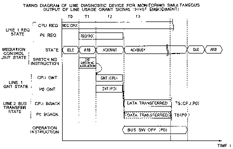
FIG. 3 is a timing diagram showing the normal
operation of the mediation control unit, and FIG. 4
shows an effect on the data responsiveness and the data
transfer when the mediation control unit is diagnosed
via software processing.
The following describes the operation timing
diagram of the mediation control unit at a normal
operation time shown in FIG. 3. The timing diagram
shows the state of the STATE signal 23 indicating the
mediation state transition output by the mediation unit
14 in the mediation control unit 12, the state of the
line usage right grant signal GNT on the line 1 60, and
the bus transfer state on the line 2 61 when the
central processing storage unit CPU 10 and the
communication control device P0 30 issue the line usage
right request of the line 2 61 in the control device
composed of the central processing storage unit CPU 10
and the communication control device P0 30.
The STATE signal 23 has five states, T0-T4,
from the mediation operation of the line 2 61 to the
completion of bus transfer. STATE=TO, IDLE state,
indicates the idle state before the bus mediation
operation is started. STATE=T1, ARB state, indicates
that line usage right requests are issued from multiple
devices and the mediation operation is being performed.
STATE=T2, ACKWAIT state, indicates a cycle in which the
line usage right grant signal GNT is issued to a
CA 02592908 2007-06-27
- 25 -
device, selected by the mediation operation in the ARB
state, the GNT switching specification (signal) 16 is
output. FIG. 3 shows an example in which GNT is issued
to the central processing storage unit CPU 10.
STATE=T3, ACKBUSY state, indicates that the device
receiving the line usage right grant is transferring
data via the line 2 61. A state transition occurs from
T2 to T3 when the data transfer is started. FIG. 3
indicates that the central processing storage unit CPU
10 is transferring data. TS(CPU,PO) shown in the
figure indicates that the former item in parentheses is
the transfer source device and the latter is the
transfer destination device. FIG. 3 shows that data is
transferred from the central processing storage unit
CPU 10 to the communication control device P0 30.
STATE=T4, WAIT state, indicates the wait period after
the data transfer is completed and before the state
transition to the IDLE state occurs.
As shown in FIG. 3, the basic operation of
the mediation control unit is that line usage right
request signals REQ issued from multiple devices are
mediated in the STATE=T1 cycle and the line usage right
grant signal GNT is output to one device selected in
the STATE=T2 cycle to allow the device that acquires
GNT (central processing storage unit CPU 10 in FIG. 3)
to transfer data via the bus. That is, in the period
of the STATE=T2 cycle, GNT is not output to a device
other than the central processing storage unit CPU 10
CA 02592908 2007-06-27
- 26 -
(GNT to the communication control device P0 30 in FIG.
3). Such a condition, if generated, is caused by a
malfunction or a functional abnormality in the
mediation control unit 12 or a signal sticking
condition on the line 1 60. This condition may
produces an effect that causes the communication
control device P0 30 to incorrectly detect the line
usage right grant signal, with a potential that the
central processing storage unit CPU 10 and the
communication control device P0 30 transfer data and
the data correctly output by the central processing
storage unit CPU 10 is destroyed.
As described above, in the timing diagram of
line 2 61 to which multiple control devices output the
line usage right request REQ at normal operation time,
the state transition, T0-T4, repeatedly occurs under
control of the mediation control unit 12 to transfer
data. The line diagnostic device according to the
present invention provides means that monitors the
timing, the state signal, and the signals sent over the
line 1 60 on a hardware basis. FIG. 4 is an operation
timing diagram of the software-based diagnosis.
The following describes the flow of the
software-based diagnostic operation, performed by the
mediation control unit, with reference to FIG. 4. One
of the advantages of the software-based diagnostic
means is that the diagnosis rate of a diagnosis target
can be easily increased by generating a variety of
CA 02592908 2007-06-27
- 27 -
diagnostic patterns. The international safety standard
IEC61508 also defines an internal diagnostic method for
diagnosing signal sticking conditions and the mediation
operation as the safety requirements for an arbiter,
and those diagnoses can be made by the software
processing. Especially, to increase the diagnosis rate
of the LSI acting as the arbiter, it is recommended
that the arbiter function diagnosis and the internal
operation diagnosis be made.
Considering the above, the following
describes the timing diagram of the software diagnosis
shown in FIG. 4 while referencing the normal operation
of the mediation control unit shown in FIG. 3. In the
configuration shown in FIG. 1, the control device,
which transfers data between the central processing
storage unit CPU 10 and the communication control
device P0 30, performs the diagnostic processing and
the data transfer operation according to the procedure
described below.
First, the central processing storage unit
CPU 10 performs diagnostic processing 130 for the
mediation control unit and performs input processing A
133 based on input data from a controlled object.
After the input processing A 133 is completed, the
central processing storage unit CPU 10 transfers data
from the data register 11 to the data register 33 in
the communication control device P0 30 via the line 2
61. After that, the timing diagram shows that the
CA 02592908 2007-06-27
- 28 -
communication control device P0 30 acquires the line
usage right grant and transfers data to the line 2 and,
after that, the central processing storage unit CPU 10
acquires the line usage right grant again and transfers
data to the line 2. The mediation control unit 12
performs the mediation operation to switch the line
usage right grant for data transfer to allow data to be
transferred based on the timing diagram of the normal
operation shown in FIG. 3. The online processing
performed by the microprocessor in the standard central
processing storage unit CPU 10 corresponds to the input
processing A 133, input processing B 134, and operation
processing 135. Those types of processing are
performed either in parallel with the data transfer
operation on the line 2 61 or in another period to
prevent the processing of the microprocessor from
affecting the data transfer on the line 2 and from
affecting the regularity and timeliness. On the other
hand, the software-based diagnostic processing of the
mediation control unit 12 corresponds to the diagnostic
processing 130, diagnostic processing 131, and
diagnostic processing 132, and those types of
processing are performed by interrupting the data
transfer on the line 2.
While the method described above increases
the diagnosis rate though the variation in the data
timeliness depends on how often the software-based
diagnostic processing is performed, this method has a
CA 02592908 2007-06-27
- 29 -
problem in data responsiveness, regularity, and
timeliness. Therefore, the diagnostic method executed
by the line diagnostic device implemented by the
hardware monitor means of the present invention offers
solutions to those problems. The following describes
examples of the line diagnostic device of the present
invention with reference to FIG. 5 to FIG. 11.
[Description of first embodiment]
FIG. 5 and FIG. 6 show the failure mode and
the abnormal operation of the mediation control unit,
monitored and detected by the line diagnostic device,
and one solution applied when an abnormality is
detected. The description of FIG. 3 refers to the
possibility of a data conflict that may occur when the
line usage right grant signal GNT is issued from the
mediation control unit 12 to two or more devices. The
monitor unit 22 in the line diagnostic device comprises
means for monitoring and detecting this failure mode.
FIG. 5 shows the flow of diagnosis of the line
diagnostic device 20 performed when the line usage
right grant signal GNT is issued to two or more
devices, and FIG. 6 is a timing diagram showing the
operation performed when the GNT signal is issued to
two or more devices as well as an example of a
solution.
FIG. 5 shows the abnormality detection means,
one of the means included in the line diagnostic device
20, for detecting an abnormality in the mediation
CA 02592908 2007-06-27
- 30 -
control unit 12 and the flow of the diagnosis of the
means. The monitor unit 22 in the line diagnostic
device 20, which monitors the line 1 60, comprises a
simultaneous output CHK unit 25 that checks if the line
usage right grant signal GNT is output to two or more
devices. The simultaneous output CHK unit 25 monitors
if two or more line usage right grant signals GNT are
issued to two or more devices. The monitor unit 22
starts monitoring when the mediation control unit 12
enters the STATE=ARB cycle. The monitor unit 22
monitors all line usage right grant signals GNT on the
line 1 60 in the STATE=ACKWAIT cycle to check if the
signal is issued only to one device that is effective.
For example, when GNT is issued to the central
processing storage unit CPU 10, the monitor unit 22
monitors if GNT is issued also to the communication
control device P0 30 that is another device. The
detection means checks the other combinations in the
same way. If the monitor unit 22 detects a
simultaneous output event (abnormality), the GNT
simultaneous output CHK unit 25 issues an instruction
signal to the operation instruction unit 21 in the
mediation control unit 12 and, in response to this
signal, the operation instruction unit 21 outputs an
operation instruction signal to the line control unit
13.
FIG. 6 is an operation timing diagram of the
first embodiment. As described in the operation
CA 02592908 2007-06-27
- 31 -
description above, this figure shows that the line
usage right grant signal GNT is issued to the central
processing storage unit CPU 10 and the communication
control device P0 30. (In the timing diagram, the line
usage right grant signal GNT is shown as GNT(CPU) and
GNT(P0)). In this condition, the central processing
storage unit CPU 10 and the communication control
device P0 30 transfer data and, as a result, a data
conflict occurs. The line diagnostic device of the
present invention detects the simultaneous output of
the GNT signal in the STATE=ACKWAIT cycle and outputs
the operation instruction signal to the line control
unit 13 to prevent the data conflict. In response to
the operation instruction signal, the line control unit
13 outputs the switch control signal="Bus SWOFF(PO)" to
the line SW 32 of the corresponding communication
control device P0 to take an action for this situation.
In the first embodiment, the line diagnostic
device 20 detects the simultaneous output of the line
usage right grant signal GNT, generated by a failure
mode such as a signal sticking condition on the line 1
60 or an abnormality in the mediation control unit 12,
and takes an action for this situation to avoid a data
conflict on the line 2 61 and to ensure safety.
[Description of second embodiment]
FIG. 7 and FIG. 8 show the failure mode and
the abnormal operation of the mediation control unit,
monitored and detected by the line diagnostic device,
= CA 02592908 2007-06-27
- 32 -
and another action that is taken when an abnormality is
detected. FIG. 7 shows the diagnostic flow that is
executed when a line diagnostic device 20 works as
means for detecting an abnormality in the switch
control signal. FIG. 8 shows the diagnostic flow that
is executed when the line diagnostic device 20 works as
means for detecting an abnormality in the line usage
right grant signal GNT.
Referring to FIG. 7, a monitor unit 22 in a
mediation control unit 12 has a bus SW output status
CHK unit 26. The bus SW output status CHK unit 26
monitors the line 1 60 and the line 2 61. If the
safety data transfer status signal, which is a part of
the signals output by the central processing storage
unit CPU 10 or the communication control device P0 30,
indicates that "safety data is being transferred", the
bus SW output status CHK unit 26 assumes that the
safety data is being transferred and compares and
checks the on/off states between the transfer
destination address slot and the switch control signal.
The purpose of the output of the safety data transfer
status signal indicating that the safety data is being
transferred is to notify the whole control device that
the safety data is being transferred. The data
transferred to the line 2 61 is classified roughly into
two: one is "safety data" that includes input/output
data transferred to the controlled object 70 and
protection instruction data and the other is "general
CA 02592908 2007-06-27
- 33 -
data" that includes communication data used primarily
for monitoring. To protect "safety data" that is
transferred via the line 2 61 when the condition
"safety data being transferred" is detected, the line
diagnostic device of the present invention conducts
diagnosis and takes an action for a potential
abnormality so that the whole control device will not
perform a dangerous operation when an abnormality
occurs in any of the lines or in the mediation control
unit.
Referring to FIG. 8, the monitor unit 22 in
the mediation control unit 12 has a GNT output status
CHK unit 27. The GNT output status CHK unit 27
monitors the line 1 60 and the line 2 61. If the
safety data transfer status signal on the line 2 61
indicates "safety", the GNT output status CHK unit 27
assumes that the safety data is being transferred and
compares and checks the transfer destination address
slot and the GNT output destination slot.
If the means shown in FIG. 7 and FIG. 8
detects an abnormality, the operation instruction unit
21 outputs the operation instruction signal to the line
control unit 13. In response to the operation
instruction signal, the line control unit 13 identifies
that a switch control signal abnormality or a GNT
signal abnormality is generated by a failure mode in
the mediation control unit 12 and moves to the stop
processing state of the current output data. To stop
CA 02592908 2007-06-27
- 34 -
the current output data, several safety data output
stop methods are possible including the freeze of the
current output data or the output of the safety
shutdown signal. Note that the present invention is
not limited to those methods.
In the second embodiment, the line diagnostic
device detects a signal sticking condition on the line
1 60 that is considered a failure mode or the incorrect
output of the switch control signal or the GNT signal
generated by an abnormality in the mediation control
unit 12, and takes an action for those conditions to
ensure safety. More specifically, when safety data is
protected by the bus SW on/off control, the means shown
in FIG. 7 can avoid a data conflict caused by a
duplication error. For example, when the line SW of a
device that may affect the safety data is disconnected
under the bus SW on/off control, the means shown in
FIG. 7 can avoid an abnormality that may be generated
by a duplication error caused if the device whose line
SW is disconnected malfunctions and if an abnormality
occurs in the switch control signal issued to that
device. Also, the means shown in FIG. 8 can prevent
the timeout of the GNT signal output to an incorrect
slot and a data conflict caused when a duplication
failure occurs. Thus, as in the first embodiment, the
means ensures the safety of the data transfer in the
control device and the safety of the mediation control
operation.
CA 02592908 2007-06-27
- 35 -
[Description of third embodiment]
FIG. 9 shows the failure mode and the
abnormal operation of the mediation control unit,
monitored and detected by the line diagnostic device,
and another action that is taken when an abnormality is
detected. FIG. 9 shows the diagnostic flow that is
executed when a line diagnostic device 20 works as
abnormality detection means for detecting an
abnormality in the state transition in the mediation
control unit 12.
Referring to FIG. 9, the monitor unit 22 in
the mediation control unit 12 has a state transition
CHK unit 28. The state transition CHK unit 28 monitors
a mediation state transition STATE signal 23 output by
the mediation control unit 12, the line 1 60, and the
line 2 61. The state transition CHK unit 28 checks the
validity of the state transition sequence of the
mediation state transition STATE signal 23.
The state transition during the normal
operation executed by the mediation unit 14 of the
mediation control unit 12 shown in FIG. 2 is as shown
in FIG. 3. Usually, the state transition during the
normal operation is T0(IDLE)110 -> T1(ARB)l11 ->
T2(ACKWAIT)112 -> T3(ACKBUSY)1l3 -> T4(WAIT)114, as
shown in FIG. 9. In this embodiment, STATE signal
23=001 is output in the STATE=TO cycle, STATE signal
23=010 is output in the STATE=Tl cycle and, after the
subsequent cycles, the STATE signal 23 is output
CA 02592908 2007-06-27
- 36 -
similarly in order of 01l -> 100 -> 101. The state
transition CHK unit 28 monitors the state using CHK1
100, CHK2 101, CHK3 102, CHK4 103, and CHK5 104
corresponding to the STATE signals 23 output during the
state transition and, if a state abnormality is
detected, takes the same output data stop action that
is taken in the second embodiment. CHK1-CHK5,
implemented not by the software but by the hardware,
starts checking when the switching trigger signal,
which switches the state, is received. The state
transition CHK unit 28 in the monitor unit 22 has a
checking unit 29 that compares and checks the STATE
signal expected value of CHK1-CHK4 and the actual STATE
signal 23 output by the mediation unit 14 in FIG. 2,
thus acting as means for checking using the switching
trigger signal.
An example of the abnormal operation is that
the state detected by CHK1 is normal (CHK1
100=STATE=001), the state detected by CHK2 is normal
(CHK2 101=STATE=010), and the state detected by CHK3 is
abnormal (CHK3 102=STATE=100 (expected value=011)),
meaning that a state transition abnormality is detected
in the ACKWAIT state detected by CHK3 102. In this
case, the output timing of the GNT switching
specification (signal) 16 shown in FIG. 2 is incorrect
and the line usage right grant signal GNT is output to
two or more device, with a possibility that a data
conflict occurs on the line 2 61. When the abnormality
CA 02592908 2007-06-27
- 37 -
is detected, the state transition CHK unit 28 notifies
the condition to the operation instruction unit 21 as
the function abnormality of the mediation control unit
12 and takes the output data stop action by means of
the method shown in the second embodiment.
In the third embodiment, a state transition
abnormality in the mediation unit 14 in the mediation
control unit 12 that is considered a failure mode, an
error in the internal logic state transition status
bit, or a state transition abnormality generated by a
signal sticking condition in the LSI for implementing
the operation of the mediation control unit is
detected, and an action is taken for them. This
ensures the safety of the data transfer in the control
device and the safety of the mediation control
operation in the same way as in the first embodiment.
[Description of fourth embodiment]
FIG. 10 and FIG. 11 show the diagnostic test
means of the line diagnostic device. FIG. 10 shows the
operation flow when the line diagnostic device conducts
a test. FIG. 11 is an operation timing diagram.
A control device in FIG. 10 comprises a
central processing storage unit CPU 10 and a line
diagnostic device 20. The central processing storage
unit CPU 10 comprises a microprocessor P 170 that
generates a diagnostic test pattern used by the line
diagnostic device 20 for conducting a diagnostic test
via software processing, a diagnostic test pattern
CA 02592908 2007-06-27
- 38 -
storage unit 15 that stores a generated test pattern,
and a line control unit 13 that transfers a diagnostic
test pattern via a line 2 61. Next, the configuration
of the line diagnostic device 20 is as follows. The
line diagnostic device 20 comprises a monitor unit 22
that monitors the signals sent via a line 1 60 and the
line 2 61, a diagnostic test pattern setting unit 124
that stores a diagnostic test pattern generated by the
central processing storage unit CPU 10 and transferred
via the line 2 61, a diagnostic control unit 125 that
controls the start of a diagnostic test by a software
instruction issued from a microprocessor 14 of the
central processing storage unit CPU 10, and a switch
SW-A 120 and a switch SW-B 1.21 that switch the
operation between the normal monitor operation and the
diagnostic test operation when the diagnostic test
start instructions 122 and 123 are executed by the
diagnostic control unit in response to the diagnostic
test instructions 126 and 127.
The following describes the operation flow
with reference to FIG. 10. The microprocessor P 170
of the central processing storage unit CPU 10 creates a
test pattern for use by the line diagnostic device 20
and writes the created diagnostic test pattern in the
diagnostic test pattern storage unit 15. This
diagnostic test pattern is either written once at
initialization time or updated and rewritten at each
execution time. Two types of diagnostic pattern are
CA 02592908 2007-06-27
- 39 -
prepared and written: one is a pattern used by the line
diagnostic device 20 to detect a normal operation and
the other is a pattern used by the line diagnostic
device 20 to detect an abnormal operation. FIG. 11
shows the detailed contents of a test pattern table.
The test pattern information created by the
microprocessor P 170 is as follows. The patterns
simulating the simultaneous output of the line usage
right grant signal GNT described in the first
embodiment, that is, a "GNT signal normal pattern" 160
that is a normal pattern and a "GNT signal abnormal
pattern" 161 that is an abnormal pattern, are generated
and stored. Similarly, the patterns simulating the
switch control signal abnormality described in the
second embodiment, that is, a "switch control signal
normal pattern" 162 that is a normal pattern and a
"switch control signal abnormal pattern" 163 that is an
abnormal pattern, are generated and stored. Similarly,
the patterns simulating the state abnormality of the
state controlling STATE signal 23 described in the
third embodiment, that is, a "state transition STATE
signal normal pattern" 164 that is a normal pattern and
a "state transition STATE signal abnormal pattern" 165
that is an abnormal pattern, are generated and stored.
The microprocessor P 170 of the central processing
storage unit CPU 10 sequentially reads the test
patterns and writes the test patterns, which have been
read, in the diagnostic test pattern setting unit 124
CA 02592908 2007-06-27
- 40 -
in the line diagnostic device 20 via the line 2 61.
When the writing of the test patterns is completed, the
microprocessor P 170 of the central processing storage
unit CPU 10 issues a diagnostic test instruction 127 to
the diagnostic control. unit 125 in the line diagnostic
device 20 via the line 2 61. In response to this
diagnostic test instruction, the diagnostic control
unit 125 outputs the switching instruction signals 122
and 123, respectively, to the switch SW-A 120 and the
switch SW-B 121. The switch SW-A 120 is the switching
switch of the line 2 61, and the switch SW-B 121 is the
switching switch of the line 1 60. Both switches
perform switching between data/signals, received from
the line 1 and the line 2, and a data pattern read from
the diagnostic test pattern setting unit, and outputs
the data/signals or the data pattern to the monitor
unit 22. During the normal operation, the switch SW-A
120 and the switch SW-B 121 are connected,
respectively, to the line 1 60 and the line 2 61. The
switching instruction signals 122 and 123, output by
the diagnostic control unit 125 in response to the
diagnostic test instruction 127, cause the switch SW-A
120 and the switch SW-B 121 to be connected to the
diagnostic test pattern setting unit 124. After the
switching operation is completed, the test pattern data
stored in the diagnostic test pattern setting unit 124
is output to the monitor unit 22 via the switch SW-A
120 and the switch SW-B 121. After receiving the test
CA 02592908 2007-06-27
- 41 -
pattern, the monitor unit 22 performs the test
operation of the monitor unit and, if a normal pattern
is received, writes the result in the diagnostic status
unit 125. If an abnormal pattern is received, the
monitor unit 22 writes the result also in the
diagnostic status unit 125. After the writing of the
diagnostic test is completed, the diagnostic test
writing completion flag is set in the diagnostic status
unit 125 to send a completion notification 126 to the
central processing storage unit CPU 10. In response to
the completion notification 126, the central processing
storage unit CPU 10 reads the result information stored
in the diagnostic status unit 125, and determines the
result. The expected value when the normal pattern is
written is "status=normal" and the expected value of
the abnormal pattern is "status=abnormal". If the
result is not an expected value, it is determined that
a diagnostic test error occurs. A diagnostic test
error, if detected, means that the diagnostic operation
performed by the line diagnostic device 20 for the
mediation control does not function correctly. When
the operation is being performed normally, there is no
problem even if the diagnostic test is discarded.
However, if a duplication error (diagnostic test error
and a mediation control unit error) is generated, the
abnormality in the mediation control unit cannot be
detected and, in this case, the safety may be affected.
This means that, when the central processing storage
CA 02592908 2007-06-27
- 42 -
unit CPU 10 detects a diagnostic test error, it is
necessary to stop the safety data output.
FIG. 12 is an operation timing diagram
showing the diagnostic test operation performed by the
line diagnostic device 20. FIG. 12 is a diagram
showing the timing analysis of the diagnostic test
operation among the central processing storage unit CPU
10, the line diagnostic device 20 of the present
invention, another input device 1, and the line 2 61.
The central processing storage unit CPU 10 first
conducts the diagnostic test of the line 2 61. The
central processing storage unit CPU 10 outputs a line 2
diagnostic test instruction 140 to cause a line 2
diagnostic device to perform diagnostic test processing
145 for the line 2 61. After the processing is
completed, the central processing storage unit CPU 10
receives a termination acknowledgement ACK 141 to
acknowledge the completion of the processing. After
the line 2 diagnostic test processing is completed, the
central processing storage unit CPU 10 starts the
diagnostic test performed by the line diagnostic device
20 and the diagnostic test processing of other devices.
As described in FIG. 10 and FIG. 11 of this embodiment,
the central processing storage unit CPU 10 issues a
test pattern setting 142 and issues a diagnostic test
trigger instruction 143. This causes the devices to
start the diagnostic test operations 146 and 147 and,
finally, the central processing storage unit CPU 10
CA 02592908 2007-06-27
- 43 -
receives the termination acknowledgement ACK 144 as the
termination acknowledgement and acknowledges the
completion of the processing.
In the fourth embodiment, the diagnostic test
conducted by the line diagnostic device 20 of the
present invention is performed using test patterns
generated by the microprocessor P 170 of the central
processing storage unit CPU 10 for ensuring the safety
when a duplication failure occurs. The diagnostic test
processing is performed by allocating a part of the
software processing time to the test processing in a
control cycle during the execution of online
processing.
Although the devices, such as the line
diagnostic device 20, are shown using the functional
block diagram in the above description, the central
processing storage unit and the functions described
above may also be created as programs.
Embodiments of the present invention will be
described below with reference to the drawings. In all
of the drawings, the same reference numeral is
basically given to components having the same function
and repetitive description will not be given.
[Description of fifth embodiment]
F'IG. 13 is a diagram showing the
configuration of a bus system in another embodiment of
the present invention.
A master (A) 301, a master (B) 302, a slave
CA 02592908 2007-06-27
- 44 -
(A) 303, and a slave (B) 304 are connected to a bus 305
via bus switches 331-334, respectively.
Bus switch control signal (swc) 321-324,
output by a switch control unit 311, switch the bus
switches 331-334 between the ON state and the OFF
state. In the description below, the state is ON when
the bus switch control signal (swc) is 1, and OFF when
the bus switch control signal is 0.
The master (A) 301 is connected to the bus
305 when the bus switch 331 is ON, and is disconnected
from the bus 305 when the bus switch 331 is OFF. The
same applies to the master (B) 302, slave (A) 303, and
slave (B) 304.
A bus arbiter 312 is a part that mediates
requests to avoid a conflict when multiple masters
request the use of the bus 305. For example, the bus
arbiter receives an asserted request (req) signal 361
from the master (A) 301, and an asserted req signal 362
from the master (B) 302 and, as a result of mediation,
asserts an acknowledge (ack) signal 351 or 352 of one
of the masters.
The master (A) 301 or master (B) 302, whose
ack signal is asserted, transfers data via the bus 305
and, after the transfer is terminated, negates the req
signal and, in response to it, the ack signal is
negated.
The switch control unit 311 in FIG. 13 is a
part that generates the bus switch control signals
CA 02592908 2007-06-27
- 45 -
(swc) for the masters and the slaves. The switch
control unit 311 receives the ack signal 351 of the
master (A) 301, an ack signal 352 of the master (B)
302, an address signal 393 used by the master (A) 301
for specifying a transfer destination slave, and an
address signal 394 used by the master (B) 302 for
specifying a transfer destination slave.
Note that there are two types of data
transfer used for transferring data in the bus system
of the system. The first data transfer is the transfer
of data whose priority is higher than that of other
(second) transfer data, for example, the transfer of
data necessary to maintain the safety operation of the
system. In another example, the first data is data
related to the basic function of the system, and the
other (second) transfer data is data related to the
auxiliary function of the system.
In FIG. 13, the master (A) 301 and the slave
(A) 303 are a part where the first data of the system
is transferred, while the master (B) 302 and the slave
(B) 304 are a part where the second data of the system
is transferred. The first data in this embodiment is a
target of functional safety that is transferred by
priority. It is assumed that safety data is
transferred only from the master (A) 301 to the slave
(A) 303. The master (B) 302 and the slave (B) 304 are
a part where relatively low priority ordinary data, not
related to functional safety, is transferred and is not
CA 02592908 2007-06-27
- 46 -
a target of functional safety.
In addition, a priority (safety) data signal
371, output by the master (A) 301, is 1 in the period
of time during which the master (A) 301 transfers the
first (safety) data in the bus system in FIG. 13, and
is 0 in the other periods.
FIG. 14 is a diagram showing an example of
the actual configuration of the switch control unit 311
in the fifth embodiment shown in FIG. 13 of the present
invention.
In the period when the value of the priority
(safety) data signal 371 is 1 and the priority (safety)
data of functional safety is transferred, the value of
a priority (safety) data signal 384 inverted by a NOT
gate 376 becomes 0.
When the value of the ack signal 351 sent to
the master (A) 301 is 1, an OR gate 377 sets the value
of the bus switch control signal (swc) 321 of the
master (A) 301 to 1. Similarly, when the value of the
ack signal 352 sent to the master (B) 302 is 1, an OR
gate 378 sets the value of the bus switch control
signal (swc) 322 of the master (B) 302 to 1. When the
value of the priority (safety) data signal 371 is 1,
the values of the bus switch control signals (swc) 323
and 324 for the slaves are determined as follows.
The address signal 393 of the slave accessed
by the master (A) 301 and the address signal 394 of the
slave accessed by the master (B) 302 are output by a
CA 02592908 2007-06-27
- 47 -
selector 372 as a selection address signal 395. The
output of the selector 372 is selected by the ack
signal 351 sent to the master (A) 301 and the ack
signal 352 sent to the master (B) 302. The bus arbiter
312 mediates the ack signal 351 and the ack signal 352
so that only one of them is set to 1. The selection
address signal 395 is decoded by an address decoder 374
from which slave selection signals 381 and slave
selection signal 382 are output. The value of the
slave selection signal 381 is 1 when the slave (A) 303
is specified as the transfer destination as a result of
address decoding, and is 0 when the slave (A) 303 is
not specified as the transfer destination. This
applies also to the slave selection signal 382 used to
specify the slave (B) 304. An ack effective signal
383, whose value is set to 1 by an OR gate 375 when one
of the values of the ack signals 351 and 352 is 1, is
input to AND-OR gates 379 and 380. That is, the bus
switch control signal (swc) 323 sent to the slave (A)
303 causes the master to select the slave (A) 303 as
the transfer destination when the priority (safety)
data signal 371 is 1. Its value remains 1 only when
the ack signal to one of the masters is effective and
data is being transferred; otherwise, the value is 0.
The value of the bus switch control signal (swc) 324
sent to the slave (B) 304 also varies in the same way
the bus switch control signal (swc) 323 sent to the
slave (A) 303 varies.
CA 02592908 2007-06-27
- 48 -
On the other hand, in the period when the
value of the priority (safety) data signal 371 is 0 and
ordinary data not related to functional safety is
transferred, the value of the priority (safety) data
signal 384 inverted by the NOT gate 376 is 1.
Therefore, the values of the bus switch control signals
(swc) 321-324, output from the OR gates 377 and 378 and
the AND-OR gates 379 and 380, are all set to 1.
FIG. 15 is an example of the timing diagram
when priority (safety) data is transferred in the
embodiment of the present invention in FIG. 13 and FIG.
14. The figure is a timing diagram when the value of
the priority (safety) data signal 371 is 1 and the
safety data, indicated by a broken line 391 in FIG. 13,
is transferred from the master (A) 301 to the slave (A)
303. In the timing diagrams in the description below,
it is assumed that the value of a signal is 1 when the
signal is asserted and is 0 when the signal is negated
and that the address bus and the data bus in the timing
diagram are lines included in the bus 305.
From clock cycle tO to clock cycle tl in FIG.
15, data is not transferred on the bus, the value of
the priority (safety) data signal 371 is 0, and the bus
switch control signals (swc) of the masters and slaves
are all 1.
Assume that the master (A) 301 asserts the
req signal 361 of the master (A) 301 in clock cycle t2
to request the bus for transferring priority (safety)
CA 02592908 2007-06-27
- 49 -
data to the slave (A) 303. This req signal 361 remains
asserted till the data transfer of the master (A) 301
is terminated.
Judging that the master (A) 301 is the only
master that issues a request in clock cycle t2, the bus
arbiter 312 asserts the ack signal 351 of the master
(A) 301 in clock cycle t3. The master (A) 301, which
has the ack signal 351 asserted, asserts the priority
(safety) data signal 371 and negates the bus switch
control signal (swc) 322 of the master (B) 302. In
addition, the address included in the selection address
signal 395 is decoded to find that the slave is the
slave (A) 303, and the bus switch control signal (swc)
324 of the slave (B) 304 is negated.
The timing diagram shown in FIG. 15 indicates
that the address bus includes the address of the slave
(A) 303 from cycle t3 to cycle t6 and that the data bus
includes safety data from cycle t5 to cycle t6.
Assume that the slave (B) 304 fails during
the transfer of the priority (safety) data from clock
cycle t5 to clock cycle t6 in FIG. 15 and incorrect
data, which flows unintentionally into the bus 305,
disturbs the data. In this case, the value of the bus
switch control signal (swc) of the slave (B) 304 is 0
in the cycle from t3 to t6 and, as shown in FIG. 13,
the bus switch 334, which is OFF, disconnects the slave
(B) 304 from the bus 305. Therefore, the transfer of
the priority (safety) data between the master (A) 301
CA 02592908 2007-06-27
- 50 -
and the slave (A) 303 via the bus 305 is not affected,
and the reliability of the priority (safety) data is
ensured.
FIG. 16 is a diagram showing the states of
the bus switches during the transfer of ordinary data
in the bus system in the fifth embodiment of the
present invention, shown in FIG. 13, when the value of
the priority (safety) data signal 371 is 0.
The switch control unit 311 shown in FIG. 16
is the same switch control unit that is shown in FIG.
14. When the value of the priority (safety) data
signal 371 is 0, the values of the bus switch control
signals (swc) 321-324 are all 1 and the bus switch 331-
334 are all ON.
FIG. 17 is a diagram showing an example of
the timing diagram of the bus system in the embodiment
of the present invention shown in FIG. 16 when the
value of the priority (safety) data signal 371 is 0 and
ordinary data, indicated by a broken line 392 (FIG.
16), is transferred from the master (B) 302 to the
slave (B) 304.
Because the value of the priority (safety)
data signal 371 is 0 in the period from clock cycles uO
to u9 in FIG. 17, the values of all bus switch control
signals (swc) of the masters and slaves are 1 and all
bus switches are ON.
In clock cycle ul, the master (B) 302 that
transfers ordinary data to the slave (B) 304 asserts
CA 02592908 2007-06-27
- 51 -
the req signal 362 of the master (B) 302 to request the
bus 305. Because the master (B) 302 is the only master
that issues a request in clock cycle ul, the ack signal
352 of the master (B) 302 is asserted in clock cycle
u2. Therefore, data is transferred from the master (B)
302 to the slave (B) 304 in the period from u2 to u5.
In clock cycle u3, the master (A) 301 that
transfers ordinary data to the slave (A) 303 asserts
the req signal 361 of the master (A) 301 to request the
bus 305. However, because the master (B) 302 is using
the bus 305, the master (A) 301 must wait until clock
cycle u6 when the master (B) 302 terminates the
transfer. Because the master (A) 301 is the only
master that requests the bus in clock cycle u6, the
master (A) 301 transfers data to the slave (A) 303
beginning in clock cycle u7.
Assume that the master (A) 301 or the slave
(A) 303 fails during the transfer of data from the
master (B) 302 to the slave (B) 304 in FIG. 17 and
incorrect data, which flows unintentionally into the
bus 305, disturbs the data. In this case, because the
transferred data is not priority (safety) data but
ordinary data, the functional safety is not affected
and the system is not endangered.
Note that the bus system may be configured in
such a way that the part corresponding to the switch
control unit and the address signals are built in the
master, which output safety data, to allow the switch
CA 02592908 2007-06-27
- 52 -
control signal to be output from the master.
In the above embodiment, the masters and
slaves, which transfer first data and second data, are
mixed on the bus in the bus system where multiple
masters and slaves are connected to orie bus. The first
data is priority (safety) data whose reliability must
be guaranteed, and the second data is ordinary data
other than priority (safety) data. That is, the master
and the slave, which handle priority (safety) data, and
the master and the slave, which does not handle
priority (safety) data, are mixed on the bus. In this
case, even if the master or the slave not related to
the transfer of priority (safety) data fails during the
transfer of the priority (safety) data on the bus, the
priority (safety) data can be transferred correctly.
That is, even if the failed mater or slave
unintentionally flows incorrect data into the bus, the
bus switch control disconnects a part not related to
the transfer to allow the priority (safety) data to be
transferred correctly.
In addition, when ordinary data that is not
priority (safety) data is transferred, setting all bus
switches to ON to make the configuration compatible
with a conventional bus to allow the design of this
embodiment to be added and applied to an existing bus
system easily.
Although the address bus and the data bus are
separate in FIG. 15 and FIG. 17, priority (safety) data
CA 02592908 2007-06-27
- 53 -
can also be transferred reliably using a period during
which the request signal is asserted, even if addresses
and data are sent in a time-dividing manner via one
shared bus.
In addition, if the salves have the direct
memory access function for transferring data between
the slaves, the control operation to switch the bus
switches between ON and OFF also enables priority
(safety) data to be transferred reliably. Ordinary
data can also be transferred compatibly with a
conventional bus.
Another advantage is that adding only the bus
switches and the switch control unit without
multiplexing the bus, masters, and salves can also
implement a safe, reliable bus system.
[Description of sixth embodiment]
Next, an example of a method for diagnosing a
bus switch sticking condition in a bus system in a
sixth embodiment of the present invention will be
described.
FIG. 18 is a block diagram of a bus system
having the function to diagnose a bus switch OFF
sticking condition in an embodiment of the present
invention. This bus system is similar to that in FIG.
13 except that a switch diagnosis unit 313 and a switch
diagnostic mode signal (swd) 373 are added.
A master (A) 306 contains a data register 341
that holds data, and a master (B) 307, a slave (A) 308,
CA 02592908 2007-06-27
- 54 -
and a slave (B) 309 also contain data registers 342,
343, and 344, respectively. Those data registers 341-
344 are interconnected via a register access unit 315
contained in the switch diagnosis unit 313 so that they
can access each other via the bus 305. The register
access unit 315 writes specified data to, and reads
data from, the data registers 341-344.
A diagnostic mode register 345 contained in
the switch diagnosis unit 313 is a two-bit register.
Changing the value of the diagnostic mode register 345
changes the value of the switch diagnostic mode signal
(swd) 373. The value of 1 of the low-order bit of the
switch diagnostic mode signal (swd) 373 indicates the
switch diagnostic processing mode in which a check is
made if the bus switch is in a sticking condition,
while the value of 0 indicates the normal operation
mode.
In the switch diagnostic mode, the value of
the high-order bit of the switch diagnostic mode signal
(swd) 373 is directly output to bus switch control
signals (swc) 325-328.
FIG. 19 is a detailed block diagram showing
the switch control unit in the embodiment of the
present invention shown in FIG. 18. The figure shows
an example of the actual configuration of a switch
control unit 314 shown in FIG. 18. This switch control
unit is similar to the switch control unit 311 shown in
FIG. 14 except that the switch diagnostic mode signal
CA 02592908 2007-06-27
- 55 -
(swd) 373 and selectors 385-388 are added. In FIG. 19,
the selector 385 receives the value of a switch
diagnostic mode signal (swd) [0] 367 to select one of
the bus switch control signal (swc) 321 and a switch
diagnostic mode signal (swd) [1] 366, and generates the
bus switch control signal (swc) 325 for the master (A)
306. This also applies to the bus switch control
signals (swc) 326-328 for the master (B) 307, slave (A)
308, and slave (B) 309. When the value of the switch
diagnostic mode signal (swd) [0] 367 is 1, all bus
switch control signals (swc) have the same value.
The value of the two bits of the switch
diagnostic mode signal (swd) 373 is 11 in FIG. 18,
meaning that the switch diagnostic processing is
performed. The values of the bus switch control
signals (swc) 325-328 are all 1 and, as a result, the
bus switches 331-334 are all ON. At this time, the
register access unit 315 makes a register access 396 to
the data register 341 of the master (A) 306. During
the register access 396, the register access unit 315
writes diagnostic data in the data register 341 and,
after writing the diagnostic data, reads the same data
register 341. If the data written immediately before
is read, it is determined that the bus switch 331 is
correctly ON.
Conversely, if the data written immediately
before is not read but different data or an arbitrary
value is read, it is determined that the bus switch 331
CA 02592908 2007-06-27
- 56 -
sticks to the OFF state. Therefore, this read/write
operation can avoid a situation in which data cannot be
transferred due to a failure in the master (A) 306 and
the system is endangered.
In this way, this embodiment can diagnose
that the bus switch 331 of the master (A) 306 does not
stick to the OFF state but is correctly in the ON
state.
The bus switches 332-334 of the master (B)
307, slave (A) 308, and slave (B) 309 can also be
diagnosed in the same way to check whether or not the
switch sticks to the OFF state.
Next, FIG. 20 is a block diagram of a bus
system having a mechanism to diagnose the ON sticking
condition of bus switches in another embodiment of the
present invention. In FIG. 20, because the value of
the two bits of the switch diagnostic mode signal (swd)
373 shown in FIG. 18 is 01, the switch diagnostic
processing is performed. The values of the bus switch
control signals (swc) 325-328 are all 0. As a result,
the bus switches 331-334 are all OFF. At this time,
the register access unit 315 makes a register access
397 to the data register 342 of the master (B) 307 as
indicated by the broken line. During the register
access 397, the register access unit 315 writes
diagnostic data and, after writing the diagnostic data,
reads the same data register 342. If the data written
immediately before is not read but different data or an
CA 02592908 2007-06-27
- 57 -
arbitrary value is read, it is determined that the bus
switch 332 is correctly OFF.
Conversely, if the data written immediately
before is read, it is determined that the bus switch
332 sticks to the ON state. As a result, this
read/write operation can avoid a situation in which
another failure in the master (B) 307 adversely affects
the bus 305.
In this way, this embodiment can diagnose
that the bus switch. 332 of the master (B) 307 does not
stick to the ON state but is correctly in the OFF
state.
The bus switches 331, 333, and 334 of the
master (A) 306, slave (A) 308, and slave (B) 309 can
also be diagnosed in the same way to check whether or
not the switch sticks to the ON state.
FIG. 21 is a timing diagram showing the
processing flow of the bus system and the switch
diagnostic processing in the embodiment of the present
invention shown in FIG. 18 and FIG. 20.
After the bus system power is turned on,
start processing 441 is performed first and, before
normal processing is started, switch diagnostic
processing 442 is performed. The switch diagnostic
processing refers to the processing for checking if the
bus switch sticks to the ON state and to the OFF state
as described in FIG. 18 and FIG. 20. After the switch
diagnostic processing 442 is terminated normally,
CA 02592908 2007-06-27
- 58 -
processing 1, processing 2, and processing 3 are
performed as normal processing. After that, the switch
diagnostic processing is performed regularly in such a
way that switch diagnostic processing 443 is performed
after normal processing is performed for a fixed period
of time, switch diagnostic processing 444 is performed
after normal processing is performed for a fixed period
of time, and so on.
If a bus switch sticking failure is detected
in the switch diagnostic processing 442-444, the
processing is terminated abnormally and a notification
is sent to the system to avoid a dangerous situation.
According to another embodiment of the
present invention described above, the diagnosis can
detect a potential failure that may be caused when a
bus switch sticks, increasing the reliability of the
bus system and reducing the possibility that the whole
system is endangered.
Although the switch diagnostic mode signal
(swd) 373 is represented by the 2-bit line in this
embodiment, it is also possible to provide the signal
into two: the diagnostic mode switching signal and
diagnostic data signal.
Although the means is disclosed in the
embodiment for detecting a bus switch failure by
writing to and reading from a data register, the
diagnostic communication path of the communication path
diagnostic device, disclosed in JP-A-2006-139634, may
CA 02592908 2007-06-27
- 59 -
also be used to detect a bus switch sticking failure.
Next, the following describes the structure
of a bus switch used in the bus system of the present
invention.
FIGs. 22A, 22B, and 22C are diagrams showing
an example of the configuration of a transistor cell
used for the bus switch in the embodiment of the
present invention. FIG. 22A shows an example in which
an MOS switch 401 is used as the bus switch. This MOS
switch 401, in which the value of a control signal 402
determines whether an input 403 is sent to an output
404, is configured by connecting the input 403 to a
master or a slave and by connecting the output 404 to
the bus.
In this configuration, the bus switch is
implemented by controlling the value of the control
signal 402 in such a way that the MOS switch is set to
ON to set the bus switch to ON and that the MOS switch
is set to OFF to set the bus switch to OFF.
FIG. 20B shows an example in which a selector
405 is used as the bus switch.
This selector 405, in which a control signal
406 causes one of an input (A) 407 and an input (B) 408
to be transmitted to an output 409, is configured by
connecting one of the input (A) 407 and the input (B)
408 to a master or a slave and by connecting the output
409 to the bus.
The input not connected to the master is set
CA 02592908 2007-06-27
- 60 -
to a high impedance state. In this configuration, the
bus switch is implemented by controlling the value of
the control signal 406 in such a way that the input to
which the master is connected is selected to set the
bus switch to ON and that the high impedance input is
selected to set the bus switch to OFF.
FIG. 22C shows an example in which a tri-
state buffer 450 is used as the bus switch.
In this tri-state buffer 450, the value of a
control signal 451 determines whether the value of an
input 452 is output to an output 453 or high impedance
is output to the output 453. This tri-state buffer 450
is configured by connecting the input 452 to a master
or a slave and by connecting the output 453 to the bus.
In this configuration, the bus switch is
implemented by controlling the value of the control
signal 451 in such a way that the value of the input
452 is output to the output 453 to set the bus switch
to ON and that the high impedance is output to the
output 453 to set the bus switch to OFF.
The use of a widely used general-purpose
transistor cell as the bus switch as described above
allows the bus switch to be implemented relatively
easily and at a low cost.
The following describes examples of
applications of the bus system according to the present
invention.
FIG. 23 is a diagram showing the block
CA 02592908 2007-06-27
- 61 -
configuration in which the bus system of the present
invention is applied to a power generation plant.
Basically, a power generation plant 410 is controlled
by a control device 411 based on a command issued from
a control terminal 412. The power generation plant 410
and the control device 411 are connected by an I/0
device 413, and a control monitor 414 is provided. In
the control device 411, a plant control unit 415, an
I/0 control unit 416, and a display control unit 417
are connected via a bus 418.
Basically, the power generation plant 410 is
started as follows. A command entered from the control
terminal 412 causes the I/0 control signal to be sent
from the plant control unit 415 to the I/0 control unit
416 via the bus 418. This I/0 control signal starts
the I/0 device 413 that starts the power generation
plant 410. Therefore, rather than the display control
unit 417, the plant control unit 415 and the I/0
control unit 416 perform the basic function to control
the power generation plant 410. Therefore, the I/0
control signal, which flows through the bus 418, must
be highly reliable. This I/0 control signal is the
first data having high reliability described above.
On the other hand, the display control unit
417 monitors display data flowing through the bus 418
and displays necessary information on the control
monitor 414. Therefore, this monitor-related data,
which is auxiliary function data described above for
CA 02592908 2007-06-27
- 62 -
the power generation plant 410, corresponds to the
second data.
To apply the present invention to the power
generation plant 410, the bus system is configured in
which the plant control unit 415 corresponds to the
master (A) 301 in FIG. 13, the I/O control unit 416
corresponds to the slave (A) 303 in FIG. 13, and the
display control unit 417 corresponds to the slave (B)
304 in FIG. 13. FIG. 23 shows the switch control unit
311 and the bus switches 331, 333, and 334
corresponding to those in FIG. 13.
If the display control unit 417 fails in this
application example, the display of the control monitor
414 is disturbed or erased. However, even if the
display is erased, the operation of the power
generation plant 410 is not affected and so the power
generation should be continued. It is only required
that a monitor failure can be corrected at a later time
by replacing the display control unit 417 or the
control monitor 414 when the plant is stopped.
To allow the control signal to be output to
the power generation plant 410, the bus switches 331
and 333 are set to ON and the bus switch 334 is set to
OFF as shown in the figure. Therefore, this
configuration prevents the data in the bus 418 from
being disturbed by a failure in the display control
unit 417 and from the value of the I/0 control signal
from being changed unintentionally. This means that
CA 02592908 2007-06-27
- 63 -
this configuration ensures the correct I/O control
operation, avoids the worst situation in which the
power generation plant cannot be controlled, and
increases the reliability of the power plant system.
FIG. 24 is a diagram showing the block
configuration in which the bus system of the present
invention is applied to a car system. Various ECUs
(Electric Control Unit) for controlling the driving of
a car 420 are connected to the car 420 via an in-
vehicle network 421. First, the acceleration signal,
which varies according to the pressing amount of an
accelerator pedal 22, is transmitted from an
accelerator I/0 device 423 to an engine ECU 424 to
change the number of engine rotations for changing the
speed of the car 420. The steering signal, which
varies according to the operation of a steering wheel
425, is transmitted from a steering I/0 device 426 to
steering ECUs 1571 and 1572 to change the direction of
front tires 1581 and 1582 for changing the driving
direction of the car 420. In addition, a brake signal,
which varies according to the pressing amount of a
brake pedal 429, is transmitted from a brake I/0 device
1591 to brake ECUs 1592-1595 to decelerate or stop the
car 420.
Note that, for the car 420, a command for the
steering wheel and the brake is more important than a
command for the engine. That is, a command for the
engine corresponds to the second (ordinary) data of the
CA 02592908 2007-06-27
- 64 -
present invention, and a command for the steering wheel
and the brake corresponds to the first data transfer
necessary for maintaining the safety operation of the
system.
During the period when the brake pedal 429 is
pressed and the brake command is active, the switch
control unit 311 controls the bus switches so that the
fuel injection command from the accelerator pedal 422
is inhibited. That is, bus switches 611-615 for the
brake and the bus switches 621-623 for the steering
wheel are always ON, and bus switches 631-632 for the
accelerator are set to OFF during the period when the
brake pedal 429 is pressed and the brake command is
active.
Even if the value of the acceleration signal
(fuel injection command) is garbled and the speed
changes unintentionally when the engine ECU 424 fails,
the driver can press the brake pedal 429 to stop the
car correctly for maintaining the safety of the car
system.
Even if the engine ECU 424 fails and
incorrect data flowing through the in-vehicle network
421. disturbs the operation, the driver can press the
brake pedal 429 to disconnect the engine ECU 424 from
the in-vehicle network 421 by means of the
corresponding bus switch 432 as shown in the figure.
This configuration avoids a brake failure due to a
garbled brake signal and an improper steering due to a
CA 02592908 2007-06-27
- 65 -
garbled steering signal, and ensures the safety of the
car system.
FIG. 25 is a diagram showing the block
configuration in which the bus system of the present
invention is applied to a multi-function mobile phone.
The multi-function mobile phone refers to a mobile
phone having the music function and the television
function. In this case, the multi-function mobile
phone is fundamentally a mobile phone, the bus system
is configured with priority given to the telephone
function judging that the telephone function is
considered more important than the music function and
the television function.
The internal configuration of a mobile phone
430 is that a telephone processing unit 432, a voice
input unit 433, a music function unit 434, and a
television function unit 435 are connected via a
communication bus 431.
When the mobile phone 430 is used as a
telephone that is the basic function, the telephone
processing unit 432 and the voice input unit 433 start
the operation. In this case, the switch control unit
311 sets the bus switches 611 and 612 to ON, and sets
the other bus switches 621 and 622 to OFF. In this
state, voices entered from a microphone 436 are
converted to radio waves and are transmitted to a
telephone at the other end of the line via an antenna
437 and a base station. Radio waves from the telephone
CA 02592908 2007-06-27
- 66 -
at the other end of the line, sent from a base station,
are received and converted to voices and are output to
the user via a speaker 438.
When other auxiliary functions of the mobile
phone are used, the switch control unit 311 sets all
bus switches 611, 612, 621, and 622 to ON.
First, when the music function is used, the
music function unit 434 starts the operation and
reproduces favorite music from the music data stored in
the mobile phone via the bus switch 621 and the
communication bus 431, and outputs the reproduced music
from the headphone speaker 438. Next, when the
television function is used, the television function
unit 435 starts the operation, converts the radio waves
received from the bus switch 622 via the communication
bus 431 into videos and sounds, and outputs them to a
liquid crystal monitor 439 and the (headphone) speaker
438.
Even if the music function unit 434 or the
television function unit 435 fails, the configuration
described above minimizes the failure to such a degree
that the sound or the display is disturbed or the sound
is not heard.
However, if a failure in the music function
unit 434 or the television function unit 435 causes
incorrect data to flow into the communication bus 431,
there is a possibility that the failure affects the
telephone function that is the core function, prevents
CA 02592908 2007-06-27
- 67 -
a correct telephone call from being made, and disables
the telephone function itself. To avoid this
situation, the bus switches 611 and 612 related to the
communication are set to ON and the bus switches 621
and 622 related to the music function unit 434 and the
television function unit 435 are set to OFF during a
telephone call, as shown in the figure, to prevent the
telephone function from being disturbed.
The bus system of the present invention is
applicable not only to the power generation plant, the
car, or the multi-function mobile phone such as those
shown in FIGS. 23-25, but also to a wide range of
fields such as control devices or semiconductor
integrated circuits used in industrial systems or
railway vehicles for increasing the reliability of
those systems.
It should be further understood by those
skilled in the art that although the foregoing
description has been made on embodiments of the
invention, the invention is not limited thereto and
various changes and modifications may be made without
departing from the spirit of the invention and the
scope of the appended claims.