Note: Descriptions are shown in the official language in which they were submitted.
CA 02593022 2007-06-06
WO 2006/062357 PCT/KR2005/004188
[DESCRIPTION]
[Invention Title]
VESSEL CAP AND SYSTEM FOR MANUFACTURING THE SAME
[Technical Field]
The present invention relates to a vessel cap for opening and closing a
vessel inlet and a system for manufacturing the same, and more particularly,
to a
vessel cap capable of detaching a sealing member formed at a vessel inlet from
the
vessel inlet together with an opened vessel cap by cutting the sealing member,
and
a system for manufacturing the same.
[Background Art]
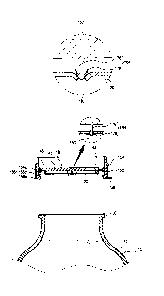
FIG. 1 is a sectional view showing a vessel cap in accordance with the
conventional art.
Generally, a beverage vessel containing liquid such as a lactobacillus
drink is provided with a vessel inlet 102, a sealing member 114 attached to
the
vessel inlet 102 for sealing a liquid material stored in a vessel 104 and thus
preventing the liquid material from being discharged outwardly, and a vessel
cap
100 for preventing the sealing member 114 from being damaged by an external
impact or by a contact with an object.
The vessel cap 100 has a cylindrical shape of which upper side is closed.
A hooking jaw 110 locked by a locking rib 108 formed at an outer
circumferential
surface of the vessel inlet 102 is formed at an inner circumferential surface
of the
vessel cap 100. A handgrip 112 held by a user in order to detach the vessel
cap 100
from the vessel inlet 102 is formed at one side of the vessel cap 100.
In the conventional art, the vessel cap 100 is detached from the vessel
inlet 102 by pulling the handgrip 112 held by the user. Then, the sealing
member
114 is removed from the vessel inlet 102, and the liquid material stored in
the
vessel is discharged out through the vessel inlet 102.
However, in the conventional vessel cap, the sealing member attached to
the vessel inlet has to be removed by the user's hand or by an additional tool
such
1
CA 02593022 2007-06-06
WO 2006/062357 PCT/KR2005/004188
as a knife, etc. after detaching the vessel cap from the vessel inlet, thereby
causing
a user's inconvenience.
Especially, when the sealing member is removed by the user's hand, the
sealing member is not smoothly detached from an edge of the vessel inlet due
to a
strong adhesion force therebetween. Therefore, the user has to remove the
sealing
member again by his hand, which causes a sanitary problem.
[Disclosure]
[Technical Problem]
Therefore, an object of the present invention is to provide a vessel cap
capable of enhancing a user's convenience by automatically removing a sealing
member by opening the vessel cap by integrally forming a sealing member
removing unit at the vessel cap without additionally removing the sealing
member.
Another object of the present invention is to provide a vessel cap capable
of preventing environment pollution due to a discarded sealing member by
storing
a sealing member removed by opening the vessel cap in the vessel cap.
Still another object of the present invention is to provide a vessel cap
capable of solving a sanitary problem that a user's hand comes in contact with
a
vessel inlet at the time of removing a sealing member by automatically
removing
the sealing member by a sealing member removing unit.
Still another object of the present invention is to provide a vessel cap
capable of reducing a production cost by manufacturing the vessel cap with one
molding.
Still another object of the present invention is to provide a vessel cap
capable of enhancing a user's convenience, shortening a manufacturing process,
and reducing a production cost by constructing a handgrip of a spoon stored in
the
vessel cap to serve as a cover for protecting the spoon without an additional
cover.
Still another object of the present invention is to provide a vessel cap
capable of preventing a pressing plate from being pressed during a non-usage
due
to an external force by fixing the pressing plate of a sealing member removing
unit
to an inner circumferential surface of a body.
2
CA 02593022 2007-06-06
WO 2006/062357 PCT/KR2005/004188
[Technical Solution]
To achieve these and other advantages and in accordance with the
purpose of the present invention, as embodied and broadly described herein,
there
is provided a vessel cap, comprising: a body mounted at a vessel inlet through
which a liquid material stored in a vessel is discharged outwardly, and having
a
certain space therein; a pressing plate disposed in the body to be movable in
upper
and lower directions; a cutter formed at an edge of a lower surface of the
pressing
plate in a circumferential direction with the same gap for penetrating a
sealing
member when the pressing plate is pressed and cutting the sealing member when
the body is rotated; a hooking member downwardly protruding at the lower
surface
of the pressing plate for storing the sealing member cut by the cutter in the
body;
and a connection portion formed between an outer circumferential surface of
the
pressing plate and an inner circumferential surface of the body for guiding
the
pressing plate to be moved in upper and lower directions.
The cutter comprises a plurality of supporting portions formed at an
edge of a lower surface of the pressing plate with the same gap, a first
cutting
portion sharply formed at a lower end of the supporting portion for
penetrating the
sealing member when the pressing plate is pressed, and a second cutting
portion
formed on at least one side surface of both side surfaces of the supporting
portion
for cutting the sealing member as a circular shape when the body is rotated.
The hooking member comprises a rod downwardly extending from a
center of a lower surface of the pressing plate, and a hooking portion formed
at an
end of the rod for hooking the sealing member so that the cut sealing member
can
be stored in the body when the body is detached from the vessel inlet and
penetrating the sealing member when the pressing plate is pressed.
The vessel cap according to the present invention comprises: a body
mounted at a vessel inlet through which a liquid material stored in a vessel
is
discharged outwardly; a pressing plate disposed in the body to be movable in
upper and lower directions; at least one cutter formed at an edge of a lower
surface
of the pressing plate in a circumferential direction for penetrating a sealing
3
CA 02593022 2007-06-06
WO 2006/062357 PCT/KR2005/004188
member when the pressing plate is pressed and cutting the sealing member when
the body is rotated; a hooking member downwardly protruding at the lower
surface
of the pressing plate for storing the sealing member cut by the cutter in the
body;
and a connection portion formed between an outer circumferential surface of
the
pressing plate and an inner circumferential surface of the body and
elastically
transformed so that the pressing plate can be moved in upper and lower
directions.
The hooking member comprises a supporting rod downwardly extending
from the lower surface of the pressing plate for penetrating the sealing
member
when the pressing plate is pressed, and at least one hooking protrusion formed
at
an outer circumferential surface of the supporting rod and elastically
transformed
to be bent for hooking the sealing member.
To achieve these and other advantages and in accordance with the
purpose of the present invention, as embodied and broadly described herein,
there
is also provided a system for manufacturing a vessel cap, comprising: a first
core
having an inlet through which a molding material is injected and positioned at
an
upper side; a second core disposed at a lower side of the first core and
having a
cavity for forming a vessel cap between the first core; a third core inserted
into a
center of the second core for forming a hooking protrusion of a vessel cap;
and a
stripper plate disposed between the first core and the second core for
separating a
molded vessel cap from the first and second cores.
[Advantageous Effects]
The vessel cap having a straw according to the present invention has the
following advantages in that the sealing member removing unit is installed in
the
vessel cap. Accordingly, if the pressing plate of the sealing member removing
unit
is pressed before opening the vessel cap and then the vessel cap is opened,
the
sealing member is automatically removed from the vessel inlet thereby to
enhance
the user's convenience.
Also, the sealing member removed from the vessel inlet by opening the
vessel cap is stored in the receiving portion inside the vessel cap.
Therefore,
environment pollution due to discard the sealing member out is prevented.
4
CA 02593022 2007-06-06
WO 2006/062357 PCT/KR2005/004188
Also, since the sealing member is automatically removed by the sealing
member removing unit, a sanitary problem caused as the user's hand comes in
contact with the vessel inlet at the time of removing the sealing member can
be
solved.
Also, since the spoon handgrip covers the spoon receiving portion of the
body, an additional cover for protecting the spoon head is not required
thereby to
simplify a manufacturing process and to reduce a production cost.
[Description of Drawings]
FIG. 1 is a sectional view showing a vessel cap in accordance with the
conventional art;
FIG. 2 is a perspective view showing a vessel cap according to the first
embodiment of the present invention;
FIG. 3 is a bottom view showing the vessel cap according to the first
embodiment of the present invention;
FIG. 4 is a sectional view showing a state that the vessel cap is mounted
at a vessel according to the first embodiment of the present invention;
FIG. 5 is a perspective view showing a cutter according to the first
embodiment of the present invention;
FIG. 6 is a sectional view taken along line A-A of FIG. 5;
FIGS. 7 and 8 are sectional views showing the cutter according to other
embodiments of the present invention;
FIG. 9 is a perspective view showing a hooking member according to
the first embodiment of the present invention;
FIG. 10 is a perspective view showing the hooking member according to
other embodiments of the present invention;
FIGS. 11 and 12 are views showing an operation of a vessel cap
according to the present invention;
FIG. 13 is a sectional view showing a vessel cap according to the second
embodiment of the present invention;
FIG. 14 is an enlarged view showing a part of'B' of FIG. 13;
5
CA 02593022 2007-06-06
WO 2006/062357 PCT/KR2005/004188
FIG. 15 is an enlarged view showing a part of 'C' of FIG. 13;
FIG. 16 is a view showing an operation of the vessel cap according to
the second embodiment of the present invention;
FIG. 17 is a perspective view showing a vessel cap according to the third
embodiment of the present invention;
FIG. 18 is a bottom view showing the vessel cap according to the third
embodiment of the present invention;
FIG. 19 is a sectional view showing a state that the vessel cap is
mounted at a vessel according to the third embodiment of the present
invention;
FIG. 20 is a perspective view showing a cutter according to the third
embodiment of the present invention;
FIG. 21 is a sectional view taken along line D-D of FIG. 20;
FIG. 22 is a perspective view showing a hooking portion according to
the third embodiment of the present invention;
FIG. 23 is a view showing an operation of the vessel cap according to
the third embodiment of the present invention;
FIG. 24 is an enlarged view showing a part of'E' of FIG. 23;
FIG. 25 is a view showing an operation that the vessel cap is detached
from a vessel according to the third embodiment of the present invention;
FIG. 26 is a sectional view showing a system for manufacturing the
vessel cap according to the third embodiment of the present invention;
FIG. 27 is an enlarged view showing a part of 'F' of FIG. 26;
FIG. 28 is an enlarged view showing an operation of the system for
manufacturing the vessel cap according to the third embodiment of the present
invention;
FIG. 29 is a sectional view showing the system for manufacturing the
vessel cap of the third embodiment according to other embodiments of the
present
invention;
FIG. 30 is a sectional view taken along line G-G of FIG. 29;
FIG. 31 is a perspective view showing a state that a vessel cap is
mounted at a vessel according to the fourth embodiment of the present
invention;
FIG. 32 is a perspective view showing a state that a spoon is detached
6
CA 02593022 2007-06-06
WO 2006/062357 PCT/KR2005/004188
from the vessel cap according to the fourth embodiment of the present
invention;
FIG. 33 is a perspective view showing an inner side of the vessel cap
according to the fourth embodiment of the present invention;
FIG. 34 is a sectional view showing the vessel cap according to the
fourth embodiment of the present invention;
FIGS. 35 and 36 are perspective views showing the spoon inside the
vessel cap according to the fourth embodiment of the present invention;
FIGS. 37, 38, and 39 are views showing an operation of the vessel cap
according to the fourth embodiment of the present invention;
FIG. 40 is a perspective view showing a vessel cap according to the fifth
embodiment of the present invention;
FIG. 41 is a top view showing the vessel cap according to the fifth
embodiment of the present invention;
FIG. 42 is a sectional view showing a state that the vessel cap is
mounted at a vessel according to the fifth embodiment of the present
invention;
FIG. 43 is a perspective view showing the vessel cap according to the
fifth embodiment of the present invention;
FIGS. 44 and 45 are views showing an operation of the vessel cap
according to the fifth embodiment of the present invention;
FIG. 46 is a top view showing a vessel cap according to the sixth
embodiment of the present invention;
FIG. 47 is a sectional view taken along line H-H of FIG. 46;
FIG. 48 is a sectional view taken along line I-I of FIG. 46;
FIG. 49 is a bottom view showing a rotation force transmitting portion
of the vessel cap according to the sixth embodiment of the present invention;
FIG. 50 is a view showing an operation of the vessel cap according to
the sixth embodiment of the present invention;
FIG. 51 is a sectional view showing a vessel cap according to the
seventh embodiment of the present invention;
FIG. 52 is a perspective view showing a cutter according to the seventh
embodiment of the present invention;
FIG. 53 is a view showing an operation of the vessel cap according to
7
CA 02593022 2007-06-06
WO 2006/062357 PCT/KR2005/004188
the seventh embodiment of the present invention;
FIG. 54 a perspective view showing a vessel cap according to the eighth
embodiment of the present invention;
FIG. 55 is a sectional view showing a state that the vessel cap is
mounted at a vessel according to the eighth embodiment of the present
invention;
FIG. 56 is a perspective view showing a punch according to the eighth
embodiment of the present invention;
FIG. 57 is a perspective view showing the punch of the eighth
embodiment according to another embodiment of the present invention;
FIG. 58 is a sectional view showing the punch of the eighth embodiment
according to still another embodiment of the present invention;
FIGS. 59 and 60 are views showing an operation of the vessel cap
according to the eighth embodiment of the present invention;
FIG. 61 is a perspective view showing a vessel cap according to the
ninth embodiment of the present invention;
FIG. 62 is a top view showing the vessel cap according to the ninth
embodiment of the present invention;
FIG. 63 is a sectional view showing the vessel cap according to the ninth
embodiment of the present invention;
FIGS. 64 and 65 are views showing an operation of the vessel cap
according to the ninth embodiment of the present invention;
FIG. 66 is a sectional view showing a vessel cap according to the tenth
embodiment of the present invention;
FIG. 67 is a sectional view taken along line L-L of FIG. 66;
FIG. 68 is a perspective view showing a hooking portion of the vessel
cap according to the tenth embodiment of the present invention;
FIG. 69 is a perspective view showing a cutter according to the tenth
embodiment of the present invention;
FIGS. 70 and 71 are views showing an operation of the vessel cap
according to the tenth embodiment of the present invention;
FIG. 72 is a sectional view showing a vessel cap according to the
eleventh embodiment of the present invention;
8
CA 02593022 2007-06-06
WO 2006/062357 PCT/KR2005/004188
FIG. 73 is a frontal view showing the vessel cap according to the
eleventh embodiment of the present invention;
FIG. 74 is a perspective view showing a cutter of the vessel cap
according to the eleventh embodiment of the present invention;
FIGS. 75 and 76 are views showing an operation of the vessel cap
according to the eleventh embodiment of the present invention;
FIG. 77 is a perspective view showing the vessel cap according to the
twelfth embodiment of the present invention;
FIG. 78 is a plane view of the vessel cap of FIG. 77;
FIG. 79 is a sectional view of the vessel cap of FIG. 77;
FIG. 80 is a sectional view showing operation of the vessel cap of FIG.
77;
FIG. 81 is a perspective view showing the vessel cap according to the
thirteenth embodiment of the present invention;
FIG. 82 is a plane view of the vessel cap of FIG. 81;
FIG. 83 is a sectional view showing the vessel cap of FIG. 81 connected
with the safety member;
FIG. 84 is a sectional view showing the rotated state of the safety
member of the vessel cap of FIG. 81;
FIG. 85 is a perspective view the modified embodiment of the vessel cap
of FIG. 81;
FIG. 86 is a plane view of the vessel cap of FIG. 85;
FIG. 87 is a sectional view showing one example of the safety member
of the vessel cap of FIG. 81; and
FIG. 88 is a sectional view showing another example of the safety
member of the vessel cap of FIG. 81.
[Mode for Invention]
Hereinafter, preferred embodiments of the present invention will be
explained in more detail with reference to the attached drawings.
FIG. 2 is a perspective view showing a vessel cap according to the first
9
CA 02593022 2007-06-06
WO 2006/062357 PCT/KR2005/004188
embodiment of the present invention, FIG. 3 is a bottom view showing the
vessel
cap according to the first embodiment of the present invention, and FIG. 4 is
a
sectional view showing a state that the vessel cap is mounted at a vessel
according
to the first embodiment of the present invention.
A vessel cap 2 according to the first embodiment of the present
invention comprises a body 16 mounted at a vessel inlet 12 through which a
liquid
material stored in a vessel 10 is discharged outwardly and having a certain
space
therein, and a sealing member removing unit 18 formed in the body 16 for
removing a sealing member 20 attached to the vessel inlet 12 when the vessel
cap
2 is detached from the vessel inlet 12 and storing the removed sealing member
20
in the vessel cap 2.
The vessel 10 stores a liquid material therein, and the sealing member 20
for sealing the vessel inlet 12 and thus protecting the liquid material is
attached to
the vessel inlet 12 through which the liquid material is discharged outwardly.
Preferably, the sealing member 20 is formed of a material that can be easily
removed by a knife, etc. such as paper, an aluminum thin plate, etc.
The body 16 has a cylindrical shape, and a plurality of concave-convex
protrusions 28 for facilitating to rotate the vessel cap 2 by a user's hand
are formed
at an outer circumferential surface of the body 16. A mounting portion 34
detachably mounted at the vessel inlet 12 is formed at a lower portion of the
body
16.
The mounting portion 34 comprises two protrusions 34a and 34b
protruding from an inner circumferential surface of a lower end of the body 16
with a certain gap as a belt shape, and a hooking groove 34c formed between
the
two protrusions 34a and 34b for hooking a hooking jaw 30 formed at an outer
circumferential surface of the vessel inlet 12 and thus maintaining a mounted
state
of the vessel cap 2 to the vessel inlet 12.
A handgrip 36 held by a user and pulled for detaching the body 16 from
the vessel inlet 12 is formed at a lower end of the body 16.
Besides the aforementioned structure, a female screw portion is formed
at an inner circumferential surface of the body 16 and a male screw portion is
formed at the vessel inlet 12, so that the female screw portion is coupled to
the
CA 02593022 2007-06-06
WO 2006/062357 PCT/KR2005/004188
male screw portion.
The sealing member removing unit 18 comprises a pressing plate 40
disposed in the body 16 to be movable in upper and lower directions and
pressed
by a user, a cutter 42 formed at an edge of a lower surface of the pressing
plate 40
in a circumferential direction with the same gap for penetrating a sealing
member
20 when the pressing plate 40 is pressed and cutting the sealing member 20
when
the body 16 is rotated, a hooking member 44 downwardly protruding at the lower
surface of the pressing plate 40 for storing the sealing member cut by the
cutter 42
in the body 16, and a connection portion 46 formed between an outer
circumferential surface of the pressing plate 40 and an inner circumferential
surface of the body 16 for guiding the pressing plate 40 to be moved in upper
and
lower directions.
The pressing plate 40 is fonned as a disc shape having a diameter
smaller than an inner diameter of the body 16, and a pressing portion 50
pressed
by the user's hand is protruding from a center of an upper surface of the
pressing
plate 40. A plurality of reinforcing ribs 52 are radially formed at an outer
circumferential surface of the pressing portion 50.
The reinforcing rib 52 reinforces an intensity of the pressing plate 40
thereby to evenly distribute a force applied to press the pressing portion 50
onto
the pressing plate 40. That is, the reinforcing rib 52 allows the pressing
plate 49
pressed by the user to be entirely lowered so that the plural cutters 42 can
penetrate the sealing member 20. Preferably, the number of the reinforcing
ribs 52
is equal to the number of the cutters 42.
As shown in FIGS. 5 and 6, the cutter 42 comprises a plurality of
supporting portions 54 formed at an edge of a lower surface of the pressing
plate
40 with the same gap, a first cutting portion 56 sharply formed at a lower end
of
the supporting portion 54 and downwardly moved when the pressing plate 40 is
pressed for penetrating the sealing member 20, and a second cutting portion 58
formed on at least one side surface of both side surfaces of the supporting
portion
54 and contacting an inner circumferential surface of the vessel inlet 12 when
the
body is rotated for cutting the sealing member 20 as a circular shape.
The supporting portion 54 has a sectional surface of a trapezoid shape,
11
CA 02593022 2007-06-06
WO 2006/062357 PCT/KR2005/004188
and protrusions sharply protruding from both sides of the sectional surface
form
the second cutting portion 58. The supporting portion 54 is more inclined
towards
a center of the body 16 as it is closer to a lower end thereof. Accordingly,
when
the pressing portion 50 is pressed, the cutter 42 is prevented from coming in
contact with the vessel inlet 12.
The first cutting portion 56 is inclined towards an inner surface of the
supporting portion 54 from an outer surface of the supporting portion 54,
thereby
preventing the cutter 42 from being hooked at the vessel inlet 12 when the
cutter
42 is lowered.
Referring to FIG. 7, the cutter 42 can be formed as a curve shape having
the same curvature radius as that of an inner circumferential surface of the
vessel
inlet 12. Referring to FIG. 8, the cutter 42 can have a sectional surface of a
triangular shape.
It is also possible that the first cutting portion 56 is formed at a lower
surface of the cutter 42 and the second cutting portion 58 is formed on at
least one
side surface of both side surfaces.
As shown in FIG. 9, the hooking member comprises a rod 60
downwardly extending from a center of a lower surface of the pressing plate
40,
and a hooking portion 62 formed at an end of the rod 60 for penetrating the
sealing
member 20 when the pressing plate 40 is pressed and for hooking the sealing
member 20 so that the cut sealing member 20 can be stored in the body 16 when
the body 16 is detached from the vessel inlet 12.
The hooking portion 62 has a triangular shape and a sharp end for
penetrating the sealing member 20. An upper surface 64 of the hooking portion
62
is perpendicularly extending from an end of the rod towards both sides,
thereby
hooking a lower surface of the sealing member 20.
A pin hole 68 for passing a molding tool to mold the hooking portion 62
at the time of molding the vessel inlet 2 is formed at the pressing plate 40.
When the pressing plate 40 is lowered, the hooking member 44 is
together lowered and thus the hooking portion 62 penetrates the sealing member
20. When the body 16 is rotated by an angle of 90 or 270 the sealing member
20
is hooked at an upper surface 64 of the hooking portion 62.
12
CA 02593022 2007-06-06
WO 2006/062357 PCT/KR2005/004188
Referring to FIG. 10, the hooking member 44 is formed as a conical
shape, and a sharp end thereof penetrates the sealing member 20. The sealing
member 20 is hooked at a circular upper surface 74 of the hooking member 44.
The connection portion 46 is formed between an outer circumferential
surface of the pressing plate 40 and an inner circumferential surface of the
body 16
as a thin film having a dome shape. Also, the connection portion 46 is
elastically
transformed when the pressing plate 40 is pressed by a force more than a
certain
degree, thereby guiding the pressing plate 40 to be moved in a lower
direction.
The connection portion 46 elastically maintains a current position of the
pressing plate 40. That is, when the pressing plate 40 is upwardly protruding,
the
connection portion 46 has a convex dome shape and maintains the current state
of
the pressing plate 40. However, when the pressing plate 40 is pressed by a
force
more than a certain degree, the connection portion 46 is elastically
transformed
into a concave shape and maintains the pressed state of the pressing plate 40.
An operation of the vessel cap according to the present invention will be
explained.
FIGS. 11 and 12 are views showing an operation of the vessel cap
according to the present invention.
When the pressing plate 40 is downwardly pressed in order to discharge
the liquid material stored in the vessel 10 outwardly, the connection portion
42 is
elastically transformed and the pressing plate 40 is downwardly moved. Then,
the
first cutting portion 56 of the cutter 42 formed at a lower surface of the
pressing
plate 44 penetrates an edge of the sealing member 20, and the hooking member
44
penetrates a center of the sealing member 20.
Then, if the body 16 is rotated by the user's hand, the cutter 42 is rotated
under a contact state to an inner circumferential surface of the vessel inlet
12.
Accordingly, the second cutting portion 58 formed at both side surfaces of the
supporting portion 54 cuts the sealing member 20 as a circular shape. Herein,
the
hooking member 44 is together rotated, so that the upper surface 64 of the
hooking
portion 62 is positioned at a lower surface of the sealing member 20.
When the handgrip 36 formed at the body 16 is upwardly pulled, the
hooking jaw 30 formed at an upper surface of the vessel inlet 12 is detached
from
13
CA 02593022 2007-06-06
WO 2006/062357 PCT/KR2005/004188
the hooking groove 32 formed at an inner circumferential surface of the body
16.
Accordingly, the vessel cap 2 is detached from the vessel inlet 12.
Since the sealing member 20 that has been removed from the vessel inlet
12 is hooked at the hooking member 44, it is detached from the vessel inlet 12
together with the body 16 thus to be stored in the body 16.
FIG. 13 is a sectional view showing a vessel cap according to the second
embodiment of the present invention.
The vessel cap according to the second embodiment is applied to a
vessel having a vessel inlet 12 of a comparatively large size. A plurality of
sealing
member removing units 80 are disposed in the body 16 in a circumferential
direction. Also, a hooking unit 84 for storing the removed sealing member in
the
body is installed at the center of the body 16.
That is, in the vessel cap 2 of the second embodiment, a partition plate
82 is formed at an inner circumferential surface of the body 16, and at least
two
mounting holes 86 are formed at the partition plate 82 in a circumferential
direction. The sealing member removing unit 80 is formed at each mounting hole
86.
A mounting hole 88 is formed at a center of the partition plate 82, and
the hooking unit 84 is installed at the mounting hole 88.
As shown in FIG. 14, the sealing member removing unit 80 comprises a
connection portion 90 formed at an inner circumferential surface of the
mounting
hole 86 as a flexible bellows type, a pressing plate 92 mounted at an inner
circumferential surface of the connection portion 90 and pressed by the user,
and a
cutter 94 formed at a lower surface of the pressing plate 92 for cutting the
sealing
member 20.
A width T 1 of the connection portion 90 positioned at an edge of the
partition plate 82 is wider than a width T2 of the connection portion 90
positioned
at an inner side of the partition plate 82, so that the pressing plate 82 is
pressed
with an inclined state.
The pressing plate 92 is formed as a flat plate of a triangular shape so as
to be easily pressed with an inclined state.
One cutter 94 is formed at a lower surface of the pressing plate 92, and
14
CA 02593022 2007-06-06
WO 2006/062357 PCT/KR2005/004188
has the same shape as that of the aforementioned cutting portion.
As shown in FIG. 15, the hooking unit 84 comprises a connection
portion 96 formed at an inner circumferential surface of the mounting hole 88,
a
pressing plate 98 mounted at an inner circumferential surface of the
connection
portion 96 and pressed by the user, and a hooking member 100 formed at a lower
surface of the pressing plate 98 for penetrating the sealing member 20 and
hooking
the sealing member 20.
The connection portion 96 and the hooking member 100 have the same
structure and operation as those of the aforementioned connection portion and
the
hooking member, and thus a detail explanation thereof will be omitted.
FIG. 16 is a view showing an operation of a vessel cap according to the
second embodiment of the present invention.
An operation of the vessel cap according to the second embodiment of
the present invention will be explained. When the user downwardly presses the
pressing plate 92 of each sealing member removing unit 80 mounted at the
partition plate 82 in a circumferential direction, the connection portion 90
is
elastically transformed and the pressing plate 92 is downwardly moved.
Accordingly, the cutter 94 formed at a lower surface of the pressing plate 92
penetrates the edge of the sealing member 20.
When the user presses the pressing plate 98 of the hooking unit 84
disposed at the center of the partition plate 82, the hooking member 100
mounted
at a lower surface of the pressing plate 98 penetrates the center of the
sealing
member 20.
Under the state, if the vessel cap is rotated, the cutter 90 cuts the edge of
the sealing member 20, and the hooking member 100 is rotated thereby to hook
the
lower surface of the sealing member 20.
When the body 16 is detached from the vessel inlet 12, the sealing
member 20 is stored in the body 15 under a hooked state by the hooking member
20.
FIG. 17 is a perspective view showing a vessel cap according to the third
embodiment of the present invention, FIG. 18 is a bottom view showing the
vessel
cap according to the third embodiment of the present invention, and FIG. 19 is
a
CA 02593022 2007-06-06
WO 2006/062357 PCT/KR2005/004188
sectional view showing a state that the vessel cap is mounted at a vessel
according
to the third embodiment of the present invention.
The vessel cap according to the third embodiment of the present
invention comprises a body 150 mounted at a vessel inlet 12 through which a
liquid material stored in a vessel 10 is discharged outwardly and having a
certain
space therein, and a sealing member removing unit 152 formed in the body 150
for
removing a sealing member 20 attached to the vessel inlet 12 when the vessel
cap
is detached from the vessel inlet 12 and storing the removed sealing member 20
in
the vessel cap.
The body 150 has a cylindrical shape, and a plurality of concave-convex
protrusions 154 for facilitating to rotate the vessel cap by a user's hand are
formed
at an outer circumferential surface of the body 150. A mounting portion 156
detachably mounted at the vessel inlet 12 is formed at a lower portion of the
body
150.
The mounting portion 156 comprises two protrusions 156a and 156b
protruding from an inner circumferential surface of a lower end of the body
150
with a certain gap as a belt shape, and a hooking groove 156c formed between
the
two protrusions 156a and 156b for hooking a hooking jaw 30 formed at an outer
circumferential surface of the vessel inlet 12 and thus maintaining a mounted
state
of the vessel cap to the vessel inlet 12.
A handgrip 158 held by a user and pulled for detaching the body 150
from the vessel inlet 12 is formed at a lower end of the body 150.
Besides the above structure of the mounting portion 156, a female screw
portion is formed at an inner circumferential surface of the body 150 and a
male
screw portion is formed at the vessel inlet 12, so that the female screw
portion is
coupled to the male screw portion. That is, if the body 150 is rotated by the
user's
hand, the vessel cap is detached from the vessel inlet 12. The mounting
portion
156 can have any structure only if it can be detachably mounted at the vessel
inlet.
The sealing member removing unit 152 comprises a pressing plate 160
disposed in the body 150 to be movable in upper and lower directions and
pressed
by the user, a cutter 162 formed at an edge of a lower surface of the pressing
plate
160 in a circumferential direction with the same gap for penetrating a sealing
16
CA 02593022 2007-06-06
WO 2006/062357 PCT/KR2005/004188
member 20 when the pressing plate 160 is pressed and cutting the sealing
member
20 when the body 150 is rotated, a hooking portion 164 downwardly protruding
at
the lower surface of the pressing plate 160 for hooking the sealing member and
storing the sealing member cut by the cutter 162 in the body 150, and a
connection
portion 166 formed between an outer circumferential surface of the pressing
plate
160 and an inner circumferential surface of the body 150 for guiding the
pressing
plate 160 to be moved in upper and lower directions and supporting a moved
position of the pressing plate 160 by its elastic force.
The pressing plate 160 is formed as a disc shape having a diameter
smaller than an inner diameter of the body 150, and is disposed at a position
lower
than an upper surface of the body 150. A cover (not shown) for protecting the
pressing plate 160 can be mounted at the upper surface of the body 150.
As shown in FIGS. 20 and 21, the cutter 162 comprises a plurality of
supporting portions 170 formed at an edge of a lower surface of the pressing
plate
160 with the same gap, a first cutting portion 172 sharply formed at a lower
end of
the supporting portion 170 and downwardly moved for penetrating the sealing
member 20 when the pressing plate 160 is pressed, and a second cutting portion
174 formed on at least one side surface of both side surfaces of the
supporting
portion 170 and rotated under a contact state to an inner circumferential
surface of
the vessel inlet 12 for cutting the sealing member 20 as a circular shape when
the
body 150 is rotated.
The supporting portion 170 has a sectional surface of a trapezoid shape,
and protrusions sharply protruding from both sides of the sectional surface
form
the second cutting portion 174. The supporting portion 170 is more inclined
towards a center of the body 150 as it is closer to a lower end thereof.
Accordingly,
when the pressing portion 160 is downwardly pressed, the cutter 162 is
prevented
from coming in contact with the vessel inlet 12.
The first cutting portion 172 is inclined towards an inner surface of the
supporting portion 170 from an outer surface of the supporting portion 170,
thereby preventing the cutter 162 from being hooked at the vessel inlet 12
when
the cutter 162 is lowered.
The connection portion 166 is formed between an outer circumferential
17
CA 02593022 2007-06-06
WO 2006/062357 PCT/KR2005/004188
surface of the pressing plate 160 and an inner circumferential surface of the
body
150 as a thin film having a dome shape. Also, the connection portion 166 is
elastically transformed when the pressing plate 160 is pressed by a force more
than
a certain degree, thereby guiding the pressing plate 160 to be moved in a
lower
direction.
The connection portion 166 elastically maintains a current position of
the pressing plate 160. That is, when the pressing plate 160 is upwardly
protruding,
the connection portion 166 has a convex dome shape and maintains the current
state of the pressing plate 160. However, when the pressing plate 160 is
pressed by
a force more than a certain degree, the connection portion 166 is elastically
transformed into a concave shape and maintains the pressed state of the
pressing
plate 160.
As shown in FIG. 22, the hooking member 44 comprises a supporting
rod 176 downwardly extending from the center of the lower surface of the
pressing
plate 160 for penetrating the sealing member 20 when the pressing plate 160 is
pressed, and at least one hooking protrusion 178 formed at an outer
circumferential surface of the end of the supporting rod 176 for hooking the
sealing member 20 so as to store the sealing member cut by the cutter 162 in
the
body 150.
The supporting rod 176 is formed as a bar shape perpendicularly
extending from the center of the pressing plate 160 downwardly, and a punch
portion 180 having a sharp shape to penetrate the sealing member 20 is formed
at
the end of the supporting rod 176.
The supporting protrusion 178 formed to be elastically transformed is
upwardly bent at the time of penetrating the sealing member 20. Then, the
supporting protrusion 178 passes through a hole formed by the punch portion
180
thus to penetrate the sealing member 20. After the supporting protrusion 178
is
positioned at an inner side of the sealing member 20, it is extended into the
original state thereby to be hooked at an inner surface of the sealing member
20.
At least one hooking protrusion 178 is perpendicularly extending from
an outer circumferential surface of the supporting rod 176 with a certain
length.
Preferably, a pair of hooking protrusions 178 are formed at the outer
18
CA 02593022 2007-06-06
WO 2006/062357 PCT/KR2005/004188
circumferential surface of the supporting rod 176 with an angle of 180 .
An operation of the vessel cap according to the present invention will be
explained.
FIGS. 23 to 25 are views showing an operation of the vessel cap
according to the third embodiment of the present invention.
When the pressing plate 160 is downwardly pressed in order to
discharge the liquid material stored in the vessel 10 outwardly, the
connection
portion 166 is elastically transformed and the pressing plate 160 is
downwardly
moved. Then, the first cutting portion 172 of the cutter 162 formed at a lower
surface of the pressing plate 160 penetrates an edge of the sealing member 20,
and
the supporting rod 176 of the hooking portion 164 penetrates a center of the
sealing member 20.
The hooking protrusion 178 of the hooking member 164 is upwardly
bent at the time of penetrating the sealing member 20, and passes through a
hole
formed by the punch portion 180 of the supporting rod 176. After the
supporting
protrusion 178 is positioned at an inner side of the sealing member 20, it is
extended into the original state thereby to be hooked at an inner surface of
the
sealing member 20.
Then, if the body 150 is rotated by the user's hand, the cutter 162 is
rotated under a contact state to an inner circumferential surface of the
vessel inlet
12. Accordingly, the second cutting portion 174 formed at both side surfaces
of the
supporting portion 170 cuts the sealing member 20 as a circular shape.
When the handgrip 158 formed at the body 150 is upwardly pulled, the
hooking jaw 30 formed at an upper surface of the vessel inlet 12 is detached
from
the hooking groove 156c formed at an inner circumferential surface of the body
150. Accordingly, the vessel cap is detached from the vessel inlet 12.
Since the sealing member 20 that has been removed from the vessel inlet
12 is hooked at the hooking protrusion 178 of the hooking member 164, it is
detached from the vessel inlet 12 together with the body 150 thus to be stored
in
the body 150.
FIG. 26 is a sectional view showing a system for manufacturing the
vessel cap according to the third embodiment of the present invention, FIG. 27
is
19
CA 02593022 2007-06-06
WO 2006/062357 PCT/KR2005/004188
an enlarged view showing a part of 'F' of FIG. 26, and FIG. 28 is an enlarged
view
showing an operation of the system for manufacturing the vessel cap according
to
the third embodiment of the present invention.
A system for manufacturing a vessel cap according to the third
embodiment of the present invention serves to mold a vessel cap. The system
comprises a first core 202 having an inlet 200 through which a molding
material is
injected and positioned at an upper side, a second core 206 disposed at a
lower
side of the first core 202 and having a cavity 204 for forming a vessel cap
between
the first core 202, a third core 208 inserted into a center of the second core
206 for
forming a hooking protrusion 178 of a vessel cap, and a stripper plate 210
disposed between the first core 202 and the second core 206 for separating a
molded vessel cap from the first core and the second core.
The cavity 204 having a shape of the vessel cap and into which the
molding material is injected is formed between the first core 202 and the
second
core 206.
A supporting rod molding portion 212 for molding the supporting rod
176 of the vessel cap is formed at the center of the second core 206. A
hooking
protrusion molding portion 214 for molding the hooking protrusion 178
extending
to an outer side of the supporting rod 176, and a punch molding portion 216
for
molding the punch portion 180 formed at the end of the supporting rod 178 are
formed at an upper end of the third core 208.
Since the hooking protrusion 178 is horizontally extending from the
supporting rod 176, it is hooked at the first core and the second core when
the
molding material is detached from the cores after molding the vessel cap. To
solve
the problem, the hooking protrusion molding portion 214 is formed at the third
core 208 and the third core 208 is separated from the second core 206. As the
result, a lower portion of the molded hooking protrusion 178 becomes free.
Under
the state, if the hooking protrusion 178 is instantaneously inserted into the
supporting rod molding portion 212, the hooking protrusion 178 passes through
the supporting rod molding portion 212 with being bent downwardly. Then, the
hooking protrusion 212 is elastically restored into the original state.
A process for manufacturing a vessel cap by the system according to the
CA 02593022 2007-06-06
WO 2006/062357 PCT/KR2005/004188
first embodiment of the present invention will be explained.
A molding material is injected into the cavity 204 formed between each
core 202, 206, and 208 through the inlet 200 formed at the first core 202.
When the vessel cap is completed, the first core 202 is upwardly pulled.
Then, the third core 208 is downwardly detached from the second core 206, and
the stripper plate 210 is upwardly moved, thereby detaching the vessel cap
from
the second core 206.
When the third core 208 is detached from the second core 206, the lower
portion of the hooking protrusion 178 becomes free. Accordingly, when the
hooking protrusion 178 formed to be elastically transformed is instantaneously
inserted into the supporting rod molding portion 212 of the second core 206,
it
passes through the supporting rod molding portion 212 with being bent. After
the
hooking protrusion 178 passes through the supporting rod molding portion 212,
it
is elastically transformed thus to be restored into the original state.
FIG. 29 is a sectional view showing the system for manufacturing the
vessel cap of the third embodiment according to other embodiments of the
present
invention, and FIG. 30 is a sectional view taken along line G-G of FIG. 29.
A system for manufacturing a vessel cap according to other embodiment
of the present invention comprises a first core 252 having an inlet 250
through
which a molding material is injected and positioned at an upper side, a second
core
256 disposed at a lower side of the first core 252 and provided with a cavity
254
having a shape of the vessel cap between the first core 252, a third core 258
inserted into the second core 256 for forming the hooking protrusion 178, and
a
stripper plate 260 disposed between the first core 252 and the second core 256
for
separating a molded vessel cap from the first core 252 and the second core
256.
An insertion hole 262 for inserting the third core 258 is formed at the
second core 256. Also, a supporting rod molding portion 264 for molding the
supporting rod 176 of the vessel cap is formed between an inner
circumferential
surface of the insertion hole 262 of the second core 256 and a lateral surface
of the
third core 258. A hooking protrusion molding portion 266 for molding the
hooking
protrusion 178 is horizontally extending from the supporting rod molding
portion
264 of the second core 256.
21
CA 02593022 2007-06-06
WO 2006/062357 PCT/KR2005/004188
The third core 258 is formed to have a circular shape. The supporting
rod molding portion 264 for molding the supporting rod 176 is formed at an
upper
surface of the third core 258. Also, an outer circumferential surface of the
third
core 258 is disposed at the hooking protrusion molding portion 266 of the
second
core 256, thereby forming one side surface of the hooking protrusion 178.
Since one side surface of the hooking protrusion 178 is formed by the
circular third core 258, the hooking protrusion 178 is curvedly formed at the
outer
circumferential surface of the supporting rod 176.
A process for manufacturing a vessel cap by the system according to
another embodiment of the present invention will be explained.
A molding material is injected into the cavity 254 formed between each
core 252, 256, and 258 through the inlet 250 formed at the first core 252.
When the vessel cap is completed, the first core 252 is upwardly pulled.
Then, the third core 258 is detached from the second core 256.
One side surface of the hooking protrusion 178 formed at the hooking
protrusion molding portion 266 becomes free. Under the state, if the stripper
plate
260 is upwardly moved, the vessel cap is detached from the second core 256.
Since one side surface of the hooking protrusion 178 becomes free, the
vessel cap is detached form the hooking protrusion molding portion 266 of the
second core 256 with being inclined towards an empty space through which the
third core 258 has passed.
The hooking protrusion 178 can be perpendicularly extending from the
supporting rod 176.
FIG. 31 is a perspective view showing a state that a vessel cap is
mounted at a vessel according to the fourth embodiment of the present
invention,
FIG. 32 is a perspective view showing a state that a spoon is detached from
the
vessel cap according to the fourth embodiment of the present invention, FIG.
33 is
a perspective view showing an inner side of the vessel cap according to the
fourth
embodiment of the present invention, and FIG. 34 is a sectional view showing
the
vessel cap according to the fourth embodiment of the present invention.
A vessel cap according to the fourth embodiment of the present
invention comprises a body 300 mounted at a vessel inlet 12 through which a
22
CA 02593022 2007-06-06
WO 2006/062357 PCT/KR2005/004188
liquid material stored in a vessel 10 is discharged outwardly and having a
certain
space therein, a sealing member removing unit 302 formed in the body 300 for
removing a sealing member 20 attached to the vessel inlet 12 when the vessel
cap
is detached from the vessel inlet 12 and storing the removed sealing member 20
in
the vessel cap, and a spoon 304 detachably mounted at an upper surface of the
body 300.
The vessel 10 stores a liquid material to drink or a material to eat by
using a spoon therein, and the sealing member 20 for sealing the vessel inlet
12
and thus protecting the liquid material stored in the vessel 10 is attached to
the
vessel inlet 12 through which the liquid material is discharged outwardly.
Preferably, the sealing member 20 is formed of a material that can be easily
removed by a knife, etc. such as paper, an aluminum thin plate, etc.
A hooking jaw 306 for detachably mounting the vessel cap is protruding
at an outer circumferential surface of the vessel inlet 12 in a
circumferential
direction.
A spoon receiving portion 308 for detachably mounting the spoon 304 is
formed at an upper surface of the body 300. A mounting hole 310 for mounting
the
sealing member removing unit 302 is formed in the body 300. Also, a mounting
portion 312 for detachably mounting the hooking jaw 306 formed at the outer
circumferential surface of the vessel inlet 12 is formed at a lower inner
circumferential surface of the body 300.
The mounting hole 310 of the body 300 is formed by an oval partition
plate 314 downwardly extending from a position eccentric from the center of
the
body 300 with a certain length. A reinforcing rib 316 for reinforcing an
intensity
of the vessel cap is radially formed between an outer circumferential surface
of the
oval partition plate 314 and an inner circumferential surface of the body 300.
The mounting portion 312 comprises a protrusion 312a protruding from
an inner circumferential surface of a lower end of the body 300 as a belt
shape,
and a hooking groove 312b formed at an inner surface of the protrusion 312a
for
hooking the hooking jaw 306 formed at an outer circumferential surface of the
vessel inlet 12 and thus maintaining a mounted state of the vessel cap to the
vessel
inlet 12.
23
CA 02593022 2007-06-06
WO 2006/062357 PCT/KR2005/004188
Besides the above structure of the mounting portion 312, a female screw
portion is formed at an inner circumferential surface of the body 300 and a
male
screw portion is formed at the vessel inlet 12, so that the female screw
portion is
coupled to the male screw portion. That is, if the body 300 is rotated by the
user's
hand, the vessel cap is detached from the vessel inlet 12. The mounting
portion
312 can have any structure only if it can be detachably mounted at the vessel
inlet.
As shown in FIGS. 35 and 36, the spoon 304 comprises a spoon
handgrip 318 mounted at the spoon receiving portion 308 formed at the body 300
and held by the user, a spoon head 320 connected to the end of the spoon
handgrip
318 for feeding a liquid material to eat to a user's mouth, and a folding
portion 322
formed between the spoon handgrip 318 and the spoon head 320 for connecting
the spoon head 320 to the spoon handgrip 318.
The spoon handgrip 318 is formed as a flat plate, and covers an upper
surface of the spoon receiving portion 308 formed at the body 300 thereby to
prevent foreign materials or dust from being introduced into the spoon head
320.
That is, the spoon handgrip 318 is formed to have the same size and shape as
those
of an upper inner circumferential surface of the spoon receiving portion 308.
When the spoon handgrip 318 is inserted into the spoon receiving portion 308,
it
prevents foreign materials from being introduced into the spoon receiving
portion
308 having the spoon head 320 therein.
The spoon receiving portion 308 has a stepped edge, and a fitting portion
326 for fitting the spoon handgrip 318 is formed at an upper circumferential
surface of the spoon receiving portion 308.
That is, the spoon handgrip 318 is forcibly fitted into the fitting portion
326 of the spoon receiving portion 308 thereby not to be detached from the
spoon
receiving portion 308. A detachment preventing jaw for stably mounting the
spoon
handgrip 318 to the spoon receiving portion 308 can be formed at an edge of
the
spoon receiving portion 308.
The spoon head 320 is foldably connected to the spoon handgrip 318,
and is received in the spoon receiving portion 308. The spoon head 320 is
mounted
at an inner upper side of the mounting hole 310 of the body 300.
The folding portion 322 is fixed to one end of the spoon handgrip 318,
24
CA 02593022 2007-06-06
WO 2006/062357 PCT/KR2005/004188
and is connected to the end of the spoon head 320 as a thin film, thereby
folding or
unfolding the spoon head 320 to/from the spoon handgrip 318.
A hooking protrusion 324 for preventing the spoon head 320 in an
unfolded state from being folded is formed at the spoon handgrip 318. That is,
the
hooking protrusion 324 is formed at the end of the spoon handgrip 318, and the
end portion thereof is curvedly formed. The hooking protrusion 324 is hooked
at
both side surfaces of the spoon head 320 when the spoon head 320 is unfolded
thereby to prevent the spoon head 320 from being folded.
Since the spoon handgrip 318 is detachably mounted at the spoon
receiving portion 308 formed at the upper surface of the body 300 thereby to
cover
the spoon receiving portion 308, foreign materials are prevented from being
introduced into the spoon head 320 with which the material to drink or to eat
comes in contact. Therefore, an additional cover for protecting the spoon head
320
is not required, thereby shortening a manufacturing process and reducing a
production cost.
The sealing member removing unit 302 comprises a pressing plate 330
disposed in the mounting hole 310 of the body 300 to be movable in upper and
lower directions and pressed by a user, a cutter 332 formed at an outer edge
of a
lower surface of the pressing plate 330 for penetrating a sealing member 20
when
the pressing plate 330 is pressed and cutting the sealing member 20 when the
body
300 is rotated, a hooking portion 334 formed at an inner edge of a lower
surface of
the pressing plate 330 for hooking the sealing member 20 so that the_sealing
member 20 cut by the cutter 332 can be stored in the body 300, and a
connection
portion 336 formed between an outer circumferential surface of the pressing
plate
330 and an inner circumferential surface of the mounting hole 310 of the body
300
for guiding the pressing plate 330 to be moved in upper and lower directions
and
supporting a moved position of the pressing plate 330 by its elastic force.
The pressing plate 330 is formed as an oval flat plate to be disposed in
the oval mounting hole 310, and is disposed at a position lower than an upper
surface of the mounting hole 310. Since the spoon head 320 is mounted at the
upper surface of the mounting hole 310, the pressing plate 330 is preferably
disposed at an inner surface of the mounting hole 310.
CA 02593022 2007-06-06
WO 2006/062357 PCT/KR2005/004188
The cutter 332 is formed at an outer edge of a lower surface of the
pressing plate 330, and has the same shape and operation as those of the
cutter of
the third embodiment. Therefore, its detail explanation will be omitted.
The hooking portion 334 comprises a supporting rod 340 downwardly
extending from the center of the lower surface of the pressing plate 330 for
penetrating the sealing member 20 when the pressing plate 330 is pressed, and
at
least one hooking rod 342 formed at an outer circumferential surface of the
end of
the supporting rod 340 for hooking the sealing member 20 so as to store the
sealing member 20 cut by the cutter 332 in the body 300.
The hooking portion 334 has the same construction and operation as
those of the hooking portion of the third embodiment, and thus its detail
explanation will be omitted.
The connection portion 336 is formed between an outer circumferential
surface of the pressing plate 330 and an inner circumferential surface of the
mounting hole 310 of the body 300 as a thin film having a dome shape. Also,
the
connection portion 336 is elastically transformed when the pressing plate 330
is
pressed by a force more than a certain degree, thereby guiding the pressing
plate
330 to be moved in a lower direction.
The connection portion 336 elastically maintains a current position of
the pressing plate 330. That is, when the pressing plate 330 is upwardly
protruding,
the connection portion 336 has a convex dome shape and maintains the current
state of the pressing plate 330. However, when the pressing plate 330 is
pressed by
a force more than a certain degree, the connection portion 336 is elastically
transformed into a concave shape and maintains the pressed state of the
pressing
plate 330.
An operation of the vessel cap according to the present invention will be
explained.
FIGS. 37, 38, and 39 are views showing an operation of the vessel cap
according to the fourth embodiment of the present invention.
First, the spoon 304 stored in the vessel cap is detached from the vessel
cap. That is, when the spoon 304 received in the spoon receiving portion 308
is
upwardly pulled, the spoon 304 is detached from the spoon receiving portion
308.
26
CA 02593022 2007-06-06
WO 2006/062357 PCT/KR2005/004188
Since the spoon handgrip 318 is disposed to cover the spoon receiving portion
308,
an additional cover for protecting the spoon head 320 is not required.
After detaching the spoon 304 from the body 300, the spoon head 320 is
unfolded. As the result, the spoon head 320 and the spoon handgrip 318 are
arranged as one straight-line thereby to complete the spoon. Since both side
surfaces of the spoon head 320 are locked by the hooking protrusion 324 of the
spoon handgrip 318, the spoon head 320 is prevented from being folded.
When the pressing plate 330 disposed at the mounting hole 310 of the
body 300 is downwardly pressed in order to discharge the liquid material
stored in
the vessel 10 outwardly, the connection portion 336 is elastically transformed
and
the pressing plate 330 is downwardly moved. Then, the cutter 332 formed at an
outer edge of a lower surface of the pressing plate 330 penetrates an edge of
the
sealing member 20, and the supporting rod 340 of the hooking portion 334
penetrates a center of the sealing member 20.
At the time of penetrating the sealing member 20, the hooking rod 342
of the hooking portion 334 is upwardly bent thus to pass through a hole
penetrated
by the supporting rod 340. Once the hooking rod 342 is positioned at an inner
surface of the sealing member 20, it is elastically transformed into the
original
state as an extended state.
Then, if the body 300 is rotated by the user's hand, the cutter 332 is
rotated under a contact state to an inner circumferential surface of the
vessel inlet
12 thereby to cut the sealing member 20 as a circular shape.
When the body 300 is upwardly pulled, the hooking jaw 306 formed at
an upper surface of the vessel inlet 12 is detached from the hooking groove
306
formed at an inner circumferential surface of the body 300. Accordingly, the
vessel cap is detached from the vessel inlet 12.
Since the sealing member 20 that has been removed from the vessel inlet
12 is locked by the hooking rod 342 of the hooking portion 334, it is detached
from the vessel inlet 12 together with the body 300 thus to be stored in the
body
300.
Then, the user feeds the liquid material stored in the vessel 10 to his
mouth by using the spoon 304.
27
CA 02593022 2007-06-06
WO 2006/062357 PCT/KR2005/004188
FIG. 40 is a perspective view showing a vessel cap according to the fifth
embodiment of the present invention, FIG. 41 is a top view showing the vessel
cap
according to the fifth embodiment of the present invention, FIG. 42 is a
sectional
view showing a state that the vessel cap is mounted at a vessel according to
the
fifth embodiment of the present invention, and FIG. 43 is a perspective view
showing the vessel cap according to the fifth embodiment of the present
invention.
A vessel cap according to the fifth embodiment of the present invention
comprises a body 400 mounted at a vessel inlet 12 through which a liquid
material
stored in a vessel 10 is discharged outwardly and having a certain space
therein,
and a sealing member removing unit 402 formed in the body 400 for removing a
sealing member 20 attached to the vessel inlet 12 when the vessel cap is
detached
from the vessel inlet 12 and storing the removed sealing member 20 in the
vessel
cap.
The vessel 10 stores a liquid material or a solid material therein, and the
sealing member 20 for sealing the vessel inlet 12 and thus protecting the
liquid
material or the solid material is attached to the vessel inlet 12 through
which the
liquid material or the solid material is discharged outwardly. Preferably, the
sealing member 20 is formed of a material that can be easily removed by a
knife,
etc. such as paper, an aluminum thin plate, etc.
A hooking jaw 30 for mounting the vessel cap is protruding at the vessel
inlet 12 in a circumferential direction.
The body 400 has a cylindrical shape, and a plurality of concave-convex
protrusions 404 for facilitating to rotate the vessel cap by a user's hand are
formed
at an outer circumferential surface of the body 400. A mounting portion 406
detachably mounted at the vessel inlet 12 is formed at a lower portion of the
body
400.
The mounting portion 406 comprises two protrusions 406a and 406b
protruding from an inner circumferential surface of a lower end of the body
400
with a certain gap as a belt shape, and a hooking groove 406c formed between
the
two protrusions 406a and 406b for hooking the hooking jaw 30 formed at an
outer
circumferential surface of the vessel inlet 12 and thus maintaining a mounted
state
of the vessel cap to the vessel inlet 12.
28
CA 02593022 2007-06-06
WO 2006/062357 PCT/KR2005/004188
A handgrip 408 held by a user and pulled for detaching the body 400
from the vessel inlet 12 is formed at a lower end of the body 400.
The sealing member removing unit 402 comprises a pressing plate 410
locked in the body 400 and unlocked to be downwardly moved when a force is
applied thereto by the user, a cutter 412 formed at an edge of a lower surface
of the
pressing plate 410 in a circumferential direction with the same gap for
penetrating
a sealing member 20 when the pressing plate 410 is pressed and cutting the
sealing
member 20 when the body 400 is rotated, and a hooking portion 414 downwardly
protruding at the lower surface of the pressing plate 410 for hooking the
sealing
member so that the sealing member cut by the cutter 412 can be stored in the
body
400.
The pressing plate 410 is formed as a disc shape having an
approximately same diameter as an inner diameter of the body 400, and is
movable
in upper and lower directions at an inner circumferential surface of the body
400.
A plurality of connection ribs 416 for maintaining a fixed state of the
pressing plate 410 to the body 400 and releasing a locked state between the
pressing plate 410 and the body 400 with being cut when the pressing plate 410
is
pressed by a force more than a certain degree are formed between an outer
circumferential surface of the pressing plate 410 and an inner circumferential
surface of the body 400.
The connection rib 416 is formed to be cut when a certain force is
applied thereto, and is cut when the pressing plate 410 is pressed to be
downwardly moved.
A plurality of guide ribs 418 are connected between an outer
circumferential surface of the pressing plate 410 and an inner circumferential
surface of the body 400 with a certain gap, thereby guiding the pressing plate
410
to be downwardly moved under a connected state to the body 400.
The guide rib 418 is formed to have an 'S' shape, and has one end
connected to the inner circumferential surface of the body 400 and another end
connected to the outer circumferential surface of the pressing plate 410. When
the
pressing plate 410 is downwardly moved, the guide rib 418 is extended thereby
to
guide the pressing plate 410 to be downwardly moved and to maintain the
29
CA 02593022 2007-06-06
WO 2006/062357 PCT/KR2005/004188
connected state of the pressing plate 410 to the body 400.
The guide rib 418 is in a state of being inserted into an insertion groove
420 formed at the outer circumferential surface of the pressing plate 410 and
an
insertion groove 422 formed at the inner circumferential surface of the body
400.
A connection belt 424 having a thin 'S' shape is formed between the two
insertion
grooves 420 and 422 and a curved portion of the guide rib 418. The connection
belt 424 is cut when the pressing plate 410 is downwardly moved.
A rotation force transmitting portion 430 for guiding the pressing plate
410 to be moved in the body 400 in upper and lower directions and rotating the
pressing plate 410 with the body 400 when the body 400 is rotated is formed
between the pressing plate 410 and the body 400.
The rotation force transmitting portion 430 comprises a guide protrusion
432 protruding at the inner circumferential surface of the body 400 in upper
and
lower directions, and a groove 434 formed at the outer circumferential surface
of
the pressing plate 410 for inserting the guide protrusion 432. The guide
protrusion
432 and the groove 434 have a sectional surface of a semi-circle shape,
respectively. Preferably, at least one rotation force transmitting portion 430
is
formed between the body 400 and the pressing plate 410.
The rotation force transmitting portion 430 can have any structure such
as a spline structure in which the pressing plate 410 can be rotated together
with
the body 400 when the body 400 is rotated.
The pressing plate 410 is fixed to the body 400 by the connection rib 416,
and thus is prevented from being pressed by an external force. When the user
presses the pressing plate 410 with a force more than a certain degree, the
connection rib 416 is cut to release the locked state of the pressing plate
410 and
thus the pressing plate 410 is downwardly moved.
However, since the pressing plate 410 and the body 400 are connected to
each other by the guide rib 418, the pressing plate 410 is prevented from
being
detached from the body 400. When the body 400 is rotated, the pressing plate
410
is rotated together with the body 400 by the rotation force transmitting
portion
430.
A plurality of the cutters 412 are formed at an edge of a lower surface of
CA 02593022 2007-06-06
WO 2006/062357 PCT/KR2005/004188
the pressing plate 410 with the same gap, and are downwardly moved when the
pressing plate 410 is pressed thus to penetrate the sealing member 20. When
the
body 400 is rotated, the cutters 412 are rotated under a contact state to an
inner
circumferential surface of the vessel inlet 12 thereby to cut the sealing
member 20
as a circular shape.
The cutter 412 has the same structure as that of the aforementioned
cutter of the third embodiment.
The hooking portion 414 comprises a supporting rod 436 downwardly
extending from the center of a lower surface of the pressing plate 410 for
penetrating the sealing member 20 when the pressing plate 410 is pressed, and
at
least one hooking protrusion 438 formed at an outer circumferential surface of
the
supporting rod 436 for hooking the sealing member 20 so as to store the
sealing
member 20 cut by the cutter 412 in the body 400.
The supporting rod 436 is formed as a bar shape perpendicularly
extending from the center of the pressing plate 410 downwardly, and an end
thereof has a sharp shape to penetrate the sealing member 20.
The supporting protrusion 438 formed to be elastically transformed is
upwardly bent at the time of penetrating the sealing member 20. After the
supporting protrusion 438 is positioned at an inner side of the sealing member
20,
it is extended into the original state thereby to be hooked at an inner
surface of the
sealing member 20.
An operation of the vessel cap according to the present invention will be
explained as follows.
FIGS. 44 and 45 are views showing an operation of the vessel cap
according to the fifth embodiment of the present invention.
When the vessel cap is not opened, the pressing plate 410 is hooked at
the body 400 by the connection rib 416. Therefore, the pressing plate 410 is
not
pressed even if an external force is applied thereto.
When the pressing plate 410 is downwardly pressed in order to
discharge the liquid material stored in the vessel 10 outwardly, the
connection rib
416 is cut and the locked state of the pressing plate 410 is released. As the
result,
the pressing plate 410 is downwardly moved in the body 400. Then, the guide
rib
31
CA 02593022 2007-06-06
WO 2006/062357 PCT/KR2005/004188
418 having an 'S' shape and connected between the pressing plate 410 and the
body 400 is extended, thereby guiding the pressing plate 410 to be downwardly
moved under a connected state to the body 400.
When the pressing plate 410 is pressed, the cutters 412 formed at a lower
surface of the pressing plate 410 penetrates an edge of the sealing member 20
and
the supporting rod 436 of the hooking portion 414 penetrates a center of the
sealing member 20.
At the time of penetrating the sealing member 20, the hooking protrusion
438 of the hooking portion 414 is upwardly bent thus to pass through a hole
penetrated by the supporting rod 436. Once the hooking protrusion 438 is
positioned at an inner surface of the sealing member 20, it is elastically
transformed into the original state as an extended state.
Then, if the body 400 is rotated by the user's hand, the rotation force of
the body 400 is transmitted to the pressing plate 410 and thus the pressing
plate
410 is rotated together with the body 400 since the groove 432 formed at the
edge
of the pressing plate 410 is in a state of being inserted into the guide
protrusion
434 formed at the inner circumferential surface of the body 400.
When the pressing plate 410 is rotated, the cutter 412 is rotated under a
contact state to an inner circumferential surface of the vessel inlet 12
thereby to cut
the sealing member 20 as a circular shape.
When the handgrip 408 formed at the body 400 is upwardly pulled, the
hooking jaw 30 formed at an upper surface of the vessel inlet 12 is detached
from
the hooking groove 406c formed at an inner circumferential surface of the body
400. Accordingly, the vessel cap is detached from the vessel inlet 12.
Since the sealing member 20 that has been removed from the vessel inlet
12 is locked by the hooking protrusion 438 of the hooking portion 414, it is
detached from the vessel inlet 12 together with the body 400 thus to be stored
in
the body 400.
FIG. 46 is a top view showing a vessel cap according to the sixth
embodiment of the present invention, and FIG. 47 is a sectional view taken
along
line H-H of FIG. 46.
The vessel cap according to the seventh embodiment is applied to a
32
CA 02593022 2007-06-06
WO 2006/062357 PCT/KR2005/004188
vessel having a vessel inlet 12 of a comparatively large size. A plurality of
sealing
member removing units 450 are disposed in the body 400 in a circumferential
direction. Also, a hooking unit 452 for storing the removed sealing member 20
in
the body 400 is installed at the center of the body 400.
That is, in the vessel cap of the seventh embodiment, a partition plate
454 is formed at an inner circumferential surface of the body 400, and at
least one
mounting hole 456 is formed at the partition plate 454 in a circumferential
direction. The sealing member removing unit 450 is formed at each mounting
hole
456.
A mounting hole 458 is formed at a center of the partition plate 456, and
the hooking unit 452 is installed at the mounting hole 458.
As shown in FIGS. 48 and 49, the sealing member removing unit 450
comprises a pressing plate 460 mounted at an inner circumferential surface of
the
mounting hole 456 and moved in upper and lower directions, a rotation force
transmitting portion 462 formed between the partition plate 454 and the
pressing
plate 460 for guiding the pressing plate 460 to be moved in the body 400 in
upper
and lower directions and rotating the pressing plate 460 with the body 400
when
the body 400 is rotated, and a cutter 464 formed at a lower surface of the
pressing
plate for cutting the sealing member 20.
The pressing plate 460 is formed as a flat plate having a triangular shape.
A plurality of 'S'-shaped guide ribs 464 are connected between an outer
circumferential surface of the pressing plate 460 and an inner circumferential
surface of the mounting hole 456 of the partition plate 454, thereby guiding
the
pressing plate 460 to be downwardly moved under a connected state to the
partition plate 454. A plurality of connection ribs 466 for maintaining a
fixed state
of the pressing plate 460 to the mounting hole 458 of the partition plate 454
and
releasing a locked state therebetween when the pressing plate 460 is pressed
are
formed between an outer circumferential surface of the pressing plate 460 and
an
inner circumferential surface of the mounting hole 456 of the partition plate
454.
The guide rib 464 and the connection rib 466 have the same construction
as the guide rib 418 and the connection rib 416 of the fifth embodiment, and
thus
their detail explanation will be omitted.
33
CA 02593022 2007-06-06
WO 2006/062357 PCT/KR2005/004188
The rotation force transmitting portion 462 comprises a guide rail 468
perpendicularly formed at a lower surface of the partition plate 454 with a
certain
length, and a guide protrusion 470 protruding at an edge of the pressing plate
460
and inserted into the guide rail 468 thus to be moved.
The guide rail 468 has a sectional surface of a semi-circle shape or a'C'
shape, and guides the guide protrusion 470 to be inserted thereinto to be
moved in
upper and lower directions. Also, when the body 400 is rotated, the guide rail
468
supports the pressing plate 460 to be rotated.
One cutter 464 is formed at an edge of a lower surface of the pressing
plate 460, and has the same shape as that of the aforementioned cutter 412 of
the
fifth embodiment.
The hooking unit 452 comprises a pressing plate 472 mounted at an
inner circumferential surface of the mounting hole 458 and pressed by the
user,
and a hooking portion 474 formed at a lower surface of the pressing plate 472
for
penetrating the sealing member 20 and hooking the sealing member 20.
A guide rib 480 and a connection rib 482 are respectively formed
between an outer circumferential surface of the pressing plate 472 and an
inner
circumferential surface of the mounting hole 458 of the partition plate 454.
The
guide rib 480 and the connection rib 482 have the same operation and
construction
as those of the guide rib 464 and the connection rib 466 formed between the
pressing plate 460 of the sealing member removing unit 450 and the mounting
hole 456, and thus their detail explanation will be omitted.
A guide protrusion 484 is formed at an outer circumferential surface of
the pressing plate 472. Also, a guide rail 486 for inserting the guide
protrusion 484
is movably formed at a lower surface of the partition plate 454, thereby
guiding
the pressing plate 472 to be downwardly moved.
The hooking portion 474 has the same structure and operation as those
of the aforementioned hooking portion 414 of the fifth embodiment, and thus
its
detail explanation will be omitted.
FIG. 50 is a view showing an operation of the vessel cap according to
the sixth embodiment of the present invention.
When the user downwardly presses the pressing plate 460 of each
34
CA 02593022 2007-06-06
WO 2006/062357 PCT/KR2005/004188
sealing member removing unit 450 mounted at the partition plate 454 in a
circumferential direction, the connection rib 466 formed between the pressing
plate 460 and the mounting hole 456 of the partition plate 454 is cut to
release the
locked state of the pressing plate 460 and thus the pressing plate 460 is
downwardly moved. While the guide rib 464 connected between the pressing plate
460 and the mounting hole 456 becomes unfolded, the connected state between
the
pressing plate 460 and the partition plate 454 is maintained. The guide
protrusion
470 formed at the edge of the pressing plate 460 is moved along the guide rail
468
formed at the lower surface of the partition plate 454, thereby guiding the
pressing
plate 460 to be perpendicularly moved.
When the pressing plate 460 is downwardly moved, the cutter 464
penetrates the sealing member 20.
When the pressing plate 472 of the hooking unit 452 is pressed, the
hooking portion 474 formed at the lower surface of the pressing plate 472
penetrates the center of the sealing member 20.
Under the state, if the body 400 is rotated, the guide protrusion 470
formed at the pressing plate 460 of each sealing member removing unit 450 is
hooked by the guide rail 468 formed at the partition plate 454. Therefore, if
the
body 400 is rotated, the pressing plate 460 is together rotated. Then, the
cutter 464
cuts the edge of the sealing member 20, and the hooking portion 474 is hooked
at
the lower surface of the sealing member 20.
When the body 400 is detached from the vessel inlet 12, the sealing
member 20 is received in the body 400 under a hooked state to the hooking
portion
474.
FIG. 51 is a sectional view showing a vessel cap according to the
seventh embodiment of the present invention, and FIG. 52 is a perspective view
showing a cutter according to the seventh embodiment of the present invention.
The vessel cap according to the seventh embodiment is the same as the
vessel cap according to the fifth embodiment except that a sealing member
receiving portion 504 for storing the sealing member 20 is formed at a cutter
502
of the sealing member removing unit 500.
The sealing member removing unit 500 according to the seventh
CA 02593022 2007-06-06
WO 2006/062357 PCT/KR2005/004188
embodiment comprises a pressing plate 510 locked in the body 400 and unlocked
at the time of being pressed by the user thus to be downwardly moved, a
rotation
force transmitting portion 512 formed between an outer circumferential surface
of
the pressing plate 510 and an inner circumferential surface of the body 400
for
guiding the pressing plate 510 to be moved in the body 400 in upper and lower
directions and transmitting a rotation force of the body 400 to the pressing
plate
510 when the body 400 is rotated, a cutter 502 formed at an edge of a lower
surface of the pressing plate 510 with the same gap for penetrating the
sealing
member 20 when the pressing plate 510 is pressed and cutting the sealing
member
20 when the body 400 is rotated, and a sealing member receiving portion 504
for
storing the sealing member 20 cut by the cutter 502 in the body 400.
A connection rib (not shown) for maintaining a fixed state of the
pressing plate 510 to an inner circumferential surface of the body 400 and
releasing a locked state of the pressing plate 510 to the body 400 with being
cut
when the pressing plate 510 is pressed by a force more than a certain degree
are
formed between the pressing plate 510 and the body 400. Also, the guide rib
418
for maintaining a connected state of the pressing plate 510 to the inner
circumferential surface of the body 400 is formed between the pressing plate
510
and the body 400.
The guide rib 418 and the connection rib have the same construction and
operation as those of the guide rib 418 and the connection rib 416 of the
fifth
embodiment, and thus their detail explanation will be omitted.
The rotation force transmitting portion 512 has the same construction
and operation as those of the aforementioned rotation force transmitting
portion
430 of the fifth embodiment, and thus their detail explanation will be
omitted.
As shown in FIG. 52, the cutter 502 comprises a plurality of supporting
portions 520 formed at an edge of a lower surface of the pressing plate 510
with
the same gap, a first cutting portion 522 sharply formed at a lower end of the
supporting portion 520 and downwardly moved when the pressing plate 510 is
pressed for penetrating the sealing member, and a second cutting portion 524
formed on at least one side surface of both side surfaces of the supporting
portion
520 for cutting the sealing member 20 as a circular shape with being rotated
under
36
CA 02593022 2007-06-06
WO 2006/062357 PCT/KR2005/004188
a contact state to the inner circumferential surface of the vessel inlet 12
when the
body 400 is rotated.
The sealing member receiving portion 504 is protruding from an inner
side surface of the supporting portion 520, and locks the edge of the sealing
member 20 cut by the cutter 502 thereby to store the sealing member 20 in the
body 400 when the body 400 is detached from the vessel inlet 12.
As shown in FIG. 53, the vessel cap according to the seventh
embodiment has the same operation as that of the vessel cap according to the
fifth
embodiment except that the sealing member 20 cut by the cutter is stored in
the
sealing member receiving portion 504 formed at an inner side surface of the
cutter
502.
FIG. 54 a perspective view showing a vessel cap according to the eighth
embodiment of the present invention, and FIG. 55 is a sectional view showing a
state that the vessel cap is mounted at a vessel according to the eighth
embodiment
of the present invention.
The vessel cap according to the eighth embodiment of the present
invention comprises a body 600 mounted at a vessel inlet 12 through which a
liquid material stored in a vessel 10 is discharged outwardly and having a
certain
space therein, and a sealing member punching unit 604 for penetrating the
sealing
member 20 attached to the vessel inlet 12 so that the liquid material stored
in the
vessel can be discharged.
A hooking jaw 30 for mounting the vessel cap is protruding at the vessel
inlet 12 in a circumferential direction.
The body 600 has a cylindrical shape, and a plurality of concave-convex
protrusions 604 for facilitating to rotate the vessel cap by a user's hand are
formed
at an outer circumferential surface of the body 600. A mounting portion 606
detachably mounted at the vessel inlet 12 is formed at a lower portion of the
body
600.
The mounting portion 606 comprises two protrusions 606a and 606b
protruding from an inner circumferential surface of a lower end of the body
600
with a certain gap as a belt shape, and a hooking groove 606c formed between
the
two protrusions 606a and 606b for hooking the hooking jaw 30 formed at an
outer
37
CA 02593022 2007-06-06
WO 2006/062357 PCT/KR2005/004188
circumferential surface of the vessel inlet 12 and thus maintaining a mounted
state
of the vessel cap to the vessel inlet 12.
A handgrip 608 held by a user and pulled for detaching the body 600
from the vessel inlet 12 is formed at a lower end of the body 600.
Besides the aforementioned structure of the mounting portion 606, a
female screw portion is formed at an inner circumferential surface of the body
600
and a male screw portion is formed at the vessel inlet 12, so that the female
screw
portion is coupled to the male screw portion. That is, if the body 600 is
rotated by
the user's hand, the vessel cap is detached from the vessel inlet 12. The
mounting
portion 606 can have any structure only if it can be detachably mounted at the
vessel inlet.
The sealing member punching unit 602 comprises a pressing plate 610
disposed in the body 600 to be movable in upper and lower directions and
downwardly moved at the time of being pressed by a user, a punch 612 formed at
a lower surface of the pressing plate 610 for forming a hole of a certain
shape at
the sealing member 20 when the pressing plate 610 is pressed, and a connection
portion 614 connected between an outer circumferential surface of the pressing
plate 610 and an inner circumferential surface of the body 600 for guiding the
pressing plate 610 to be moved in upper and lower directions and supporting a
moved position of the pressing plate 610 by its elastic force.
The pressing plate 610 is formed as a disc shape having a diameter
smaller than an inner diameter of the body 600.
As shown in FIG. 56, the punch 612 comprises a supporting rod 620
perpendicularly extending from the lower surface of the pressing plate 610 so
as to
have a certain diameter, and a punching portion 622 having a conical shape and
formed at the end of the supporting rod 620 for penetrating the sealing member
20
and punching a circular hole 626.
The punch 612 is downwardly moved when the pressing plate 610 is
pressed thus to penetrate the sealing member 20 and to form the hole 626.
Accordingly, the liquid material stored in the vessel 10 is discharged
outwardly
through the hole 626.
The reason why the hole 626 is formed at the sealing member 20 is in
38
CA 02593022 2007-06-06
WO 2006/062357 PCT/KR2005/004188
order to prevent the liquid material stored in the vessel 10 from being
discharged
out at one time by discharging the liquid material little by little through
the hole
626.
The punch 612 can have various forms according to a kind of the liquid
material stored in the vessel 10.
That is, the first punch 612 has a conical shape at an end thereof, and is
preferably applied when the material stored in the vessel 10 is a liquid
material
such as edible oil, shampoo, etc. or a liquid material having a certain
concentration.
When the material stored in the vessel 10 is a solid material having a
certain size, a hole having a cross shape is formed at the sealing member 20
in
order to discharge the material stored in the vessel 10 out one by one. That
is, as
shown in FIG. 57, a second punch 630 comprises a rod portion 632
perpendicularly extending from the lower surface of the pressing plate 610 and
having a sectional surface of a cross shape, and a punching portion 634
sharply
formed at the end of the rod portion 632 for penetrating the sealing member
20.
The second punch 630 forms a hole of a cross shape at the sealing
member 20. Therefore, the solid material stored in the vessel 10 such as a
pill, etc.
is hooked at the hole thus to be discharged out one by one.
As shown in FIG. 58, a third punch 640 is applied when the material
stored in the vessel 10 is a powder-type material, and has a plurality of pins
642 at
the lower surface of the pressing plate 610. That is, the third punch 640 is
constructed so that the powder stored in the vessel 10 can be slowly
discharged out
through a plurality of minute holes formed at the sealing member 20 when the
vessel 10 is shaken.
The punch can have various forms according to a kind of the material
stored in the vessel besides the aforementioned forms.
The connection portion 614 is formed between an outer circumferential
surface of the pressing plate 610 and an inner circumferential surface of the
body
600 as a thin film having a dome shape. Also, the connection portion 614 is
elastically transformed when the pressing plate 610 is pressed by a force more
than
a certain degree, thereby guiding the pressing plate 610 to be moved in a
lower
39
CA 02593022 2007-06-06
WO 2006/062357 PCT/KR2005/004188
direction.
The connection portion 614 elastically maintains a current position of
the pressing plate 610. That is, when the pressing plate 610 is upwardly
protruding,
the connection portion 614 has a convex dome shape and maintains the current
state of the pressing plate 610. However, when the pressing plate 610 is
pressed by
a force more than a certain degree, the connection portion 614 is elastically
transformed into a concave shape and maintains the pressed state of the
pressing
plate 610.
An operation of the vessel cap according to the present invention will be
explained.
FIGS. 59 and 60 are views showing an operation of the vessel cap
according to the eighth embodiment of the present invention.
When the pressing plate 610 is downwardly pressed in order to
discharge the liquid material stored in the vessel 10 outwardly, the
connection
portion 614 is elastically transformed and the pressing plate 610 is
downwardly
moved. Then, the punch 612 formed at the lower surface of the pressing plate
610
penetrates the sealing member 20 thus to form the hole 626 at the sealing
member
20.
The hole 626 can have various sizes and forms according to a kind of the
material stored in the vessel 10.
When the handgrip 608 formed at the body 600 is upwardly pulled, the
hooking jaw 30 formed at an upper surface of the vessel inlet 12 is detached
from
the hooking groove 606c formed at an inner circumferential surface of the body
600. Accordingly, the vessel cap is detached from the vessel inlet 12.
As the result, the punch 612 is detached from the sealing member 20,
and the hole 626 through which the material stored in the vessel 10 is
discharged
out is formed at the sealing member 20.
FIG. 61 is a perspective view showing a vessel cap according to the
ninth embodiment of the present invention, FIG. 62 is a top view showing the
vessel cap according to the ninth embodiment of the present invention, and
FIG.
63 is a sectional view showing the vessel cap according to the ninth
embodiment
of the present invention.
CA 02593022 2007-06-06
WO 2006/062357 PCT/KR2005/004188
The vessel cap according to the ninth embodiment of the present
invention comprises a body 600 mounted at a vessel inlet 12 through which a
liquid material stored in a vessel 10 is discharged outwardly and having a
certain
space therein, a pressing plate 650 disposed in the body 600 to be movable in
upper and lower directions and pressed by a user, a locking rib 652 formed
between the pressing plate 650 and an inner circumferential surface of the
body
600 for locking the pressing plate 650 to the inner circumferential surface of
the
body 600 and releasing the locked state only when the pressing plate 650 is
pressed by a force more than a certain degree, and a punch 654 formed at the
lower surface of the pressing plate 650 for punching the sealing member 20
attached to the vessel inlet 12 when the pressing plate 650 is downwardly
moved
and thus discharging the material stored in the vessel outwardly.
The pressing plate 650 is formed as a disc shape having an
approximately same diameter as an inner diameter of the body 600, and is
movable
in upper and lower directions at an inner circumferential surface of the body
600.
The locking rib 652 is connected between an outer circumferential
surface of the pressing plate 650 and an inner circumferential surface of the
body
600, and maintains a fixed state of the pressing plate 650 to the body 600.
The
locking rib 652 releases the locked state between the pressing plate 650 and
the
body 600 with being cut when the pressing plate 650 is pressed by a force more
than a certain degree.
The locking rib 652 is formed as a thin film to be cut when the pressing
plate 650 is pressed by a force more than a certain degree, thereby guiding
the
pressing plate 650 to be downwardly moved.
A plurality of guide ribs 656 are connected between an outer
circumferential surface of the pressing plate 650 and an inner circumferential
surface of the body 600 with a certain gap, thereby guiding the pressing plate
650
to be downwardly moved under a connected state to the body 600.
The guide rib 656 is formed to have an 'S' shape, and has one end
connected to the inner circumferential surface of the body 600 and another end
connected to the outer circumferential surface of the pressing plate 650. When
the
pressing plate 650 is downwardly moved, the guide rib 656 is extended thereby
to
41
CA 02593022 2007-06-06
WO 2006/062357 PCT/KR2005/004188
guide the pressing plate 650 to be downwardly moved and to maintain the
connected state of the pressing plate 650 to the body 600.
The guide rib 656 is in a state of being inserted into an insertion groove
658 formed at the outer circumferential surface of the pressing plate 650 and
an
insertion groove 660 formed at the inner circumferential surface of the body
600.
A connection belt 662 having a thin 'S' shape is formed between the two
insertion
grooves 658 and 660 and a curved portion of the guide rib 656. The connection
belt 662 is cut when the pressing plate 650 is downwardly moved.
A lift supporting portion 670 for guiding the pressing plate 650 to be
perpendicularly moved when the pressing plate 650 is downwardly moved is
formed between the outer circumferential surface of the pressing plate 650 and
the
inner circumferential surface of the body 600.
The lift supporting portion 670 comprises at least one guide protrusion
672 perpendicularly formed at the inner circumferential surface of the body
600,
and at least one guide groove 674 formed at the outer circumferential surface
of
the pressing plate 650 and moved in upper and lower directions along the guide
protrusion 672 for inserting the guide protrusion 672.
When the pressing plate 650 is downwardly moved, the guide groove
674 formed at the outer circumferential surface of the pressing plate 650 is
moved
along the guide protrusion 672 fonned at the inner circumferential surface of
the
body 600. Therefore, the lift supporting portion 670 guides the pressing plate
650
to be downwardly moved in a perpendicular direction, and guides the punch 654
to
penetrate the sealing member 20 at a precise position.
Since the pressing plate 650 is fixed to the body 600 by the locking rib
652, the pressing plate 650 is prevented from being pressed even if an
external
force is applied thereto. When the user presses the pressing plate 650 with a
force
more than a certain degree, the locking rib 652 is cut thus to release the
locked
state of the pressing plate 650 and thereby the pressing plate 650 is
downwardly
moved.
Since the pressing plate 650 and the body 600 are connected to each
other by the guide rib 656, the pressing plate 650 is prevented from being
detached
from the body 600. The lift supporting portion 670 guides the pressing plate
650 to
42
CA 02593022 2007-06-06
WO 2006/062357 PCT/KR2005/004188
be perpendicularly moved. The punch 654 has the same construction and
operation
as those of the aforementioned punch 612 of the eighth embodiment, and thus
its
detail explanation will be omitted.
An operation of the vessel cap according to the ninth embodiment of the
present invention will be explained.
FIGS. 64 and 65 are views showing an operation of the vessel cap
according to the ninth embodiment of the present invention.
When the vessel cap is not opened, the pressing plate 650 is in a locked
state at the body 600 by the locking rib 652. Therefore, the pressing plate
650 is
not pressed even if an external force is applied thereto.
When the pressing plate 650 is downwardly pressed in order to
discharge the liquid material stored in the vessel 10 outwardly, the locking
rib 652
is cut and the locked state of the pressing plate 650 is released. As the
result, the
pressing plate 650 is downwardly moved in the body 600. Then, the guide rib
656
having an 'S' shape and connected between the pressing plate 650 and the body
600 is extended, thereby guiding the pressing plate 650 to be downwardly moved
under a connected state to the body 600.
When the pressing plate 650 is pressed, the punch 654 formed at a lower
surface of the pressing plate 650 is downwardly moved to penetrates the
sealing
member 20 and to form a hole 680 at the sealing member 20.
When the pressing plate 650 is downwardly moved, the guide groove
674 formed at the outer circumferential surface of the pressing plate 650 is
perpendicularly moved under an inserted state to the guide protrusion 672
formed
at the inner circumferential surface of the body 600. Therefore, the hole 680
can be
precisely formed at a desired position of the sealing member 20 by the punch
654.
When the handgrip 608 formed at the body 600 is upwardly pulled, the
hooking jaw 30 formed at an upper surface of the vessel inlet 12 is detached
from
the hooking groove 606c formed at an inner circumferential surface of the body
600. Accordingly, the vessel cap is detached from the vessel inlet 12.
Then, the punch 654 is detached from the sealing member 20, and thus
the hole 680 through which the liquid material stored in the vessel 10 is
discharged
out, is formed at the sealing member 20.
43
CA 02593022 2007-06-06
WO 2006/062357 PCT/KR2005/004188
Therefore, the material stored in the vessel 10 is discharged out through
the hole 680.
FIG. 66 is a sectional view showing a vessel cap according to the tenth
embodiment of the present invention.
A vessel cap according to the tenth embodiment of the present invention
comprises a body 700 mounted at a vessel inlet 12 of a vessel 10 and having a
certain space therein, a cover 702 openably/closably mounted at an upper end
of
the body 700 for opening and closing the body 700, a sealing member removing
unit 704 formed in the body 700 for removing a sealing member 20 attached to
the
vessel inlet 12 when the vessel cap is detached from the vessel inlet 12 and
storing
the removed sealing member 20 in the body 700, and a discharge pipe 708 formed
in the body 700 for discharging the material stored in the vessel 10
outwardly.
The vessel 10 stores a liquid material or a solid material therein, and the
sealing member 20 for sealing the vessel inlet 12 and thus protecting the
liquid
material or the solid material is attached to the vessel inlet 12 through
which the
liquid material or the solid material is discharged outwardly. Preferably, the
sealing member 20 is formed of a material that can be easily removed by a
knife,
etc. such as paper, an aluminum thin plate, etc.
The body 700 has a cylindrical shape, and a plurality of concave-convex
protrusions 712 for facilitating to rotate the vessel cap by a user's hand are
formed
at an outer circumferential surface of the body 700. A female screw portion
716 is
formed at a lower inner circumferential surface of the body 700, and is
coupled to
a male screw portion 714 formed at an outer circumferential surface of the
vessel
inlet 12.
A skirt portion 710 for fixing the vessel cap to the vessel inlet 12 is
formed at a lower end of the body 700. When the vessel cap is opened, the
skirt
portion 710 is removed thus to be detached from the vessel inlet 12.
The cover 702 is hinge-connected to one side of the body 700 by a
connection film 718, and is openably mounted at an upper end of the body 700.
A
discharge pipe closing portion 720 for closing the discharge pipe 708 upwardly
protruding from the center of the body 700 is formed in the cover 702 with a
cylindrical shape. A handgrip 722 held by the user to open and close the cover
702
44
CA 02593022 2007-06-06
WO 2006/062357 PCT/KR2005/004188
is formed at one side of the cover 702. A hooking protrusion 726 locked by a
hooking jaw 724 protruding from an upper end of the body 700 is formed at an
inner side surface of the cover 702.
The sealing member removing unit 704 comprises a pressing plate 730
disposed in the body 700 to be movable in upper and lower directions and
pressed
by a user, a cutter 44 formed at an edge of a lower surface of the pressing
plate
730 in a circumferential direction with the same gap for penetrating a sealing
member 20 when the pressing plate 730 is pressed and cutting the sealing
member
20 when the body 700 is rotated, a hooking portion 734 downwardly extending
from the pressing plate 730 for hooking the sealing member 20 so that the
sealing
member 20 cut by a cutter 732 can be stored in the body 16, and a connection
portion 736 formed between an outer circumferential surface of the pressing
plate
730 and an inner circumferential surface of the body 700 for guiding the
pressing
plate 730 to be moved in upper and lower directions and supporting a moved
position of the pressing plate 730 by its elastic force.
The pressing plate 730 is formed as a disc shape having a diameter
smaller than an inner diameter of the body 700, and is disposed at a position
lower
than an upper surface of the body 700. The discharge pipe 708 is formed at the
center of the pressing plate 730.
An inlet 740 for returning the liquid material flowing on an outer
circumferential surface of the discharge pipe 708 after being discharged
through
the discharge pipe 708 into the vessel 10 is formed at the pressing plate 730.
Also,
a leakage preventing wall 742 for preventing the material flowing through the
discharge pipe 708 from being discharged out is upwardly extending from an
edge
of the pressing plate 730.
That is, when the liquid material remaining after being discharged
through the discharge pipe 708 flows down along the outer circumferential
surface
of the discharge pipe 708, the liquid material is collected at an upper
surface of the
pressing plate 730 by the leakage preventing wall 742. Then, the collected
liquid
material is introduced into the vessel through the inlet 740.
The discharge pipe 708 is protruding from the upper surface of the
pressing plate 730, and has a discharge passage 746 through which the liquid
CA 02593022 2007-06-06
WO 2006/062357 PCT/KR2005/004188
material stored in the vessel is discharged out. The hooking portion 734 is
formed
at the discharge passage 746 in a longitudinal direction.
As shown in FIGS. 67 and 68, the hooking portion 734 comprises a
supporting rod 750 integrally formed at an inner circumferential surface of
the
discharge passage 746 and downwardly extending from the pressing plate 730 for
penetrating the sealing member 20, and at least one hooking protrusion 752
formed at a side surface of the supporting rod 750 for hooking the sealing
member
20 so as to store the sealing member 20 cut by the cutter 732 in the body 700.
The supporting rod 750 is formed as a square bar shape downwardly
extending from an inner circumferential surface of the discharge passage 746,
and
a punch portion 754 having a sharp shape to penetrate the sealing member 20 is
formed at the end of the supporting rod 750.
The hooking protrusion 752 formed to be elastically transformed is
upwardly bent at the time of penetrating the sealing member 20. Then, the
hooking
protrusion 752 passes through a hole formed by the punch portion 754 thus to
penetrate the sealing member 20. After the hooking protrusion 752 is
positioned at
an inner side of the sealing member 20, it is extended into the original state
thereby to be hooked at an inner surface of the sealing member 20.
At least one hooking protrusion 752 is perpendicularly extending from
both side surfaces of the supporting rod 176 with a certain length.
As shown in FIG. 69, the cutter 732 comprises a plurality of supporting
portions 760 formed at an edge of a lower surface of the pressing plate 730
with
the same gap, a first cutting portion 762 sharply formed at a lower end of the
supporting portion 760 and downwardly moved when the pressing plate 730 is
pressed for penetrating the sealing member 20, and a second cutting portion
764
formed on at least one side surface of both side surfaces of the supporting
portion
760 for cutting the sealing member 20 as a circular shape with being rotated
under
a contact state to an inner circumferential surface of the vessel inlet 12
when the
body 700 is rotated.
The connection portion 736 is formed between an outer circumferential
surface of the pressing plate 730 and an inner circumferential surface of the
body
700 as a thin film having a dome shape. Also, the connection portion 736 is
46
CA 02593022 2007-06-06
WO 2006/062357 PCT/KR2005/004188
elastically transformed when the pressing plate 730 is pressed by a force more
than
a certain degree, thereby guiding the pressing plate 730 to be moved in a
lower
direction.
The connection portion 736 elastically maintains a current position of
the pressing plate 730. That is, when the pressing plate 730 is upwardly
protruding,
the connection portion 736 has a convex dome shape and maintains the current
state of the pressing plate 730. However, when the pressing plate 730 is
pressed by
a force more than a certain degree, the connection portion 736 is elastically
transformed into a concave shape and maintains the pressed state of the
pressing
plate 730.
An operation of the vessel cap according to the tenth embodiment of the
present invention will be explained.
FIGS. 70 and 71 are views showing an operation of the vessel cap
according to the tenth embodiment of the present invention.
When the user opens the cover 702 with holding the handgrip 722 and
then presses the pressing plate 730 downwardly, the connection portion 736 is
elastically transformed and the pressing plate 730 is downwardly moved. Then,
the
first cutting portion 762 of the cutter 732 formed at a lower surface of the
pressing
plate 730 penetrates an edge of the sealing member 20, and the supporting rod
750
of the hooking portion 734 penetrates a center of the sealing member 20.
The hooking protrusion 752 of the hooking portion 734 is inserted into a
hole formed by the punch portion 754 of the supporting rod 750 with being
upwardly bent. After the supporting protrusion 752 is positioned at an inner
side of
the sealing member 20, it is elastically transformed into the original state
thus to
be extended and positioned at the inner side of the sealing member 20.
Then, if the body 700 is rotated by the user's hand in a direction that the
vessel cap is opened, the cutter 732 is rotated under a contact state to an
inner
circumferential surface of the vessel inlet 12. Accordingly, the second
cutting
portion 764 formed at both side surfaces of the supporting portion 760 cuts
the
sealing member 20 as a circular shape.
Since the sealing member 20 that has been removed from the vessel inlet
12 is locked by the hooking protrusion 752 of the hooking portion 734, it is
47
CA 02593022 2007-06-06
WO 2006/062357 PCT/KR2005/004188
detached from the vessel inlet 12 together with the body 700 thus to be stored
in
the body 700.
After detaching the sealing member 20 received in the body 700 from
the body 700, the body 700 is mounted at the vessel inlet 12 with being
rotated. As
the result, the vessel cap is mounted at the vessel inlet 12 under a state
that the
sealing member 20 has been removed. Also, when the vessel 10 is inclined, the
liquid material stored in the vessel 10 is discharged out through the
discharge
passage 746 of the discharge pipe 708.
The liquid material remaining at an inlet of the discharge pipe 708 and
flowing down along an outer circumferential surface of the discharge pipe 708
is
collected at an upper surface of the pressing plate 730. The collected liquid
material returns into the vessel 10 through the inlet 740 formed at the
pressing
plate 730.
FIG. 72 is a sectional view showing a vessel cap according to the
eleventh embodiment of the present invention, and FIG. 73 is a frontal view
showing the vessel cap according to the eleventh embodiment of the present
invention.
A vessel cap according to the eleventh embodiment of the present
invention comprises a body 800 mounted at a vessel 10 and having opened upper
and lower surfaces for discharging a liquid material stored in the vessel, a
cover
802 openably/closably mounted at an upper end of the body 800 for opening and
closing the body 800, and a sealing member removing unit 804 formed in the
cover 802 for removing a sealing member 20 attached to the body 800 when the
cover 802 is opened from the body 800 and storing the removed sealing member
20 in the body 800.
The body 800 has a rectangular shape, and upper and lower surfaces
thereof are opened. The sealing member 20 for protecting the liquid material
stored in the vessel is attached to the upper surface of the body 800, and the
lower
surface of the body 800 is fixed to the vessel 10. The body 800 can have not
only
the rectangular shape but also various shapes such as a circular shape, a
polygonal
shape, etc.
The cover 802 is connected to the body 800 by a connection rib 806, and
48
CA 02593022 2007-06-06
WO 2006/062357 PCT/KR2005/004188
is openably mounted at the body 800. A handgrip 808 held by the user is formed
at
one side of the cover 802. Also, a hooking jaw 812 hooked by a hooking
protrusion 810 protruding from an outer circumferential surface of the body
800 is
formed at an inner surface of the cover 802.
The sealing member removing unit 804 comprises a pressing plate 814
disposed in the cover 802 to be movable in upper and lower directions and
pressed
by the user, a cutter 816 formed at an edge of a lower surface of the pressing
plate
814 in a circumferential direction for penetrating a sealing member 20 when
the
pressing plate 814 is pressed and cutting the sealing member 20 when the body
800 is rotated, a hooking portion 820 downwardly extending from the pressing
plate 814 for hooking the sealing member 20 so as to store the sealing member
20
cut by the cutter 816 in the cover 802, and a connection portion 818 connected
between an outer circumferential surface of the pressing plate 814 and an
inner
circumferential surface of the cover 802 for guiding the pressing plate 814 to
be
moved in upper and lower directions and supporting a moved position of the
pressing plate 814 by its elastic force.
The cover 802 has a rectangular shape, and the pressing plate 814 is
connected to an inner circumferential surface of the cover 802 by the
connection
portion 818.
When one side of the pressing plate 814 is pressed, another side of the
pressing plate 814 is not pressed due to the rectangular shape thereof. In
order to
prevent the problem, an inclination surface 830 is formed at an upper surface
of
the pressing plate 814 and thus each position of the pressing plate 814 is
sequentially pressed from a high position to a low position.
As shown in FIG. 74, the cutter 816 comprises a supporting portion 832
formed at a lower surface of the pressing plate 814 along an edge of the
pressing
plate 814 as a 'C' shape, and a cutting portion 834 formed at the end of the
supporting portion 832 and having a saw blade for penetrating an edge of the
sealing member 20 as a 'C' shape and thus cutting the sealing member 20 as a
'C'
shape when the pressing plate 814 is pressed.
When the cutter 816 is downwardly moved to cut the sealing member 20,
the supporting portion 832 is formed as a 'C' shape. Therefore, one side among
49
CA 02593022 2007-06-06
WO 2006/062357 PCT/KR2005/004188
four sides of the sealing member 20, that is, one side connected to the body
800
and the cover 802 is not removed but maintains the connected state to the body
800.
The hooking portion 820 and the connection portion 818 has the same
construction and operation as those of the hooking portion and the connection
portion of the tenth embodiment, and thus their detail explanation will be
omitted.
An operation of the vessel cap according to the eleventh embodiment
will be explained as follows.
When the user presses the pressing plate 814, the cutter 816 is lowered
thus to penetrate three sides of the sealing member 20 and to cut the three
sides.
One side of the sealing member 20 is connected to the body 800.
Since the inclination surface 830 is formed at the upper surface of the
pressing plate 814, each position of the pressing plate 814 is evenly pressed
from a
high position to a low position.
When the pressing plate 814 is pressed, the hooking portion 820 is
together lowered to penetrate the sealing member 20 and thus the sealing
member
is locked by the hooking portion 820.
Under the state, when the cover 802 is detached from the body 800 with
holding the handgrip 808 of the cover 802, the cover 802 is rotated centering
20 around the connection rib 806 thereby to be opened from the body 800. Since
the
three sides of the sealing member 20 are in a cut state, they are separated
from the
body 800 together with the cover 802. Since one side of the sealing member 20
is
attached to the body 800, the sealing member 20 is rotated centering around
the
connected portion to the body thereby to be detached from the body 800.
Meanwhile, since the pressing plate may be unexpectedly pressed and
the pressing plate breaks the sealing member, it is necessary to prevent the
pressing plate from being unexpectedly pressed, in case of the vessel cap
having
the pressing plate.
FIGS. 77 to 80 show modified examples of one of the vessel caps of the
first to third embodiments, particularly modified example of the vessel cap of
FIG.
19.
The vessel cap is further comprised of a safety member 910 for
CA 02593022 2007-06-06
WO 2006/062357 PCT/KR2005/004188
preventing the pressing plate 160 from being pressed, in addition to one of
the
structures of the vessel caps of the first to third embodiments.
As shown in FIGS. 77 to 80, one end of the safety member 910 is
connected to an upper inner portion of the body 150, and the other end of the
safety member 910 is connected to the pressing plate 160, and the safety
member
910 is broken when the pressing plate 160 is pressed with more than a
predetermined value of force. The reference number 911 indicates a through
hole
formed in the body 150 for molding the safety member 910 by using a die.
The safety member 910 prevents the pressing plate 160 from being
unexpectedly pressed until the pressing force exceeds the predetermined value.
Meanwhile, when the user wishes to remove the sealing member 20, the
user presses the pressing plate 160 with more than the predetermined force,
for
breaking the safety member 910, and then removes the sealing member 20.
In addition, the safety member 910 may be a member connected with the
body 150 of the vessel cap.
FIGS. 81 to 88 show the vessel cap in accordance with the thirteenth
embodiment of the present invention.
The safety member 910, as shown in FIGS 81 to 84, covers at least
partially the pressing plate 160, and one end of the safety member 910 is
rotatably
connected to an upper portion of the body 150, and the other end of the safety
member 910 is separatably coupled with an upper portion of the body 910 by a
hooking unit 913.
That is to say, one end of the safety member 910 is connected with the
body 150 by the connection unit 912 as one body, and the other end of the
safety
member 910 is formed with a hooking jaw 913b separatably coupled with the
hooking groove 913a formed in the body 150. Naturally, there may be various
constructions besides the hooking unit 913 of the hooking groove 913a and the
hooking jaw 913b.
Meanwhile, the body 150, the connection unit 912 and the safety
member 910 may be formed in one body.
The safety member 910 as described in the above, as shown in FIG. 83
prevents the pressing plate 160 from being unexpectedly pressed by maintaining
51
CA 02593022 2007-06-06
WO 2006/062357 PCT/KR2005/004188
the closed state.Meanwhile, when the user wishes to remove the sealing member
20, the user presses the pressing plate 160 after rotating the safety member
910, as
shown in FIG. 84.
Meanwhile, the various shapes of the body of the vessel cap having the
safety member 910 may be possible, and the body 150 of the vessel cap may have
a flat portion formed with the connection unit 912, as shown in FIGS. 85 and
86.
The flat portion formed in the body 150 make the formation of the connection
unit
912 performing a hinge of the safety member 910 more easy.
Meanwhile, the safety member 910 prevents the pressing plate 160 from
being unexpectedly pressed by external collision, etc, and needs to be
structurally
reinforced for preventing the safety member 910 from being easily bent.
Therefore,
the section of the safety member 910 may has a shape of arch, or the safety
member 910 may be reinforced by being formed with at least one protrusion in a
longitudinal direction of the safety member 910, with various methods for
structurally reinforcing the safety member 910.
52