Language selection

Search

Patent 2593100 Summary

Third-party information liability

Some of the information on this Web page has been provided by external sources. The Government of Canada is not responsible for the accuracy, reliability or currency of the information supplied by external sources. Users wishing to rely upon this information should consult directly with the source of the information. Content provided by external sources is not subject to official languages, privacy and accessibility requirements.

Claims and Abstract availability

Any discrepancies in the text and image of the Claims and Abstract are due to differing posting times. Text of the Claims and Abstract are posted:

  • At the time the application is open to public inspection;
  • At the time of issue of the patent (grant).
(12) Patent Application: (11) CA 2593100
(54) English Title: MUFFLER INSERT
(54) French Title: PIECE RAPPORTEE DE SILENCIEUX
Status: Deemed Abandoned and Beyond the Period of Reinstatement - Pending Response to Notice of Disregarded Communication
Bibliographic Data
Abstracts

English Abstract


An insert assembly for a muffler having an perforated tube for allowing
exhaust gases
travelling through the inside of the tube to escape from the inside of the
tube. The
perforated muffler insert being shaped in a polygonal configuration to allow
for increased
tube surface area providing for overall greater tube square area which
provides greater
perforation open area allowing for more efficient release of the exhaust gases
from the
interior of the muffler insert.


Claims

Note: Claims are shown in the official language in which they were submitted.

Claims
We claim:
1. A muffler insert for an exhaust muffler of the type including a perforated
core,
comprising a perforated hollow tube, said perforated hollow tube comprising of
a
multitude of vertices or raised profiles along its length or breadth.
2. The muffler insert of claim 1 comprising a perforated core shaped with a
multitude of
polygonal vertices or raised profiles aligned in the same plane as the exhaust
gas flow.
3. The muffler insert of claim 1 comprising a perforated core shaped with
continuous
columns of raised polygonal vertices or raised profiles aligned at 180 degrees
to the flow
of the exhaust gas.
4. The muffler insert of claim 1 with a perforated core shaped with non-
continuous
columns of raised polygonal vertices or raised profiles aligned at 180 degrees
to the flow
of the exhaust gas.

5. The muffler insert of claim 1 with a perforated core shaped with polygonal
vertices or
raised profiles aligned inward towards the interior of the perforated pipe
aligned in the
same plane as the exhaust gas flow.
6. The muffler insert of claim 1 with a perforated core shaped with polygonal
vertices or
raised profiles aligned inward towards the interior of the perforated pipe
aligned at 180
degrees to the flow of the exhaust gas.
7. The muffler insert of claim 1 with a perforated core shaped with polygonal
vertices or
raised profiles aligned in a spiral configuration with respect to the flow of
the exhaust
gas.
8. A muffler insert with a perforated core shaped with polygonal vertices or
raised
profiles aligned in such a fashion so as to provide for the cancellation of
exhaust waves
upon the gases exiting the perforations.
9. The muffler of claim 8 that provides for one or more perforations in one of
the vertices
or raised profile to be appropriately aligned with the corresponding
perforations of a
second vertices or raised profile so that when the exhaust gases exit the
perforations in
the vertices or raised profile they intersect or collide and provide a
cancelling wave
effect.
10. A muffler insert with a perforated core shaped with polygonal vertices or
raised
profiles aligned in a random fashion or pattern.

Description

Note: Descriptions are shown in the official language in which they were submitted.


CA 02593100 2007-05-30
FIELD OF THE INVENTION:
This invention relates generally to mufflers and more particularly to a
muffler insert for
an exhaust system of an internal combustion engine.
BACKGROUND OF THE INVENTION:
While most mufflers are of two varieties, resonator type and absorption type,
they both
employ similar insert or core designs, that being a perforated tube that
allows exhaust
gases passing through the interior of the tube to exit through the
perforations. In the case
of the absorption type of muffler the exhaust exits through the perforations
into some
type of absorption material or space to diminish the noise associated with
combustion. In
the case of resonator style mufflers the exhaust gases exit the perforations
into the interior
chambers of the muffler where they are redirected to a separate exit port in
the muffler
body. In some resonator designs the perforated tube is employed on both the
muffler
intake port and the muffler exit port. In resonator style mufflers the
perforations can also
create opposing energy waves that act to cancel each wave out thereby reducing
the
sound exiting the muffler even further.
The proposed invention provides for a similar perforated muffler tube design
however it
is designed as a polygonal with vertices or raised profiles aligned in either
the horizontal,
vertical or lateral planes, or in combination of the three, with respect to
the orientation of
the tube. The polygonal shape providing for a much improved surface area for
the tube
itself thereby increasing the available perforations for the exiting of the
exhaust gases
from the interior of the insert. A secondary consideration of the proposed
invention is that
by designing the polygonal shape to be reflective, that is when the exhaust
gases are
exiting the perforations, by design they can collide on exit creating an
effective energy
wave cancelling effect, further reducing the sound emissions from the muffler
exit port.
This type of cancelling effect is present in both resonator design and
absorption design
mufflers employing the polygonal shaped or raised profile perforated tube
inserts.

CA 02593100 2007-05-30
DESCRIPTION OF PRIOR ART
Review of the Prior Art
US Patent #6,585,078 describes an insert assembly for a muffler of a high-
performance
motor cycle, having an insert with a filling of compressed heat-resistant,
sound-absorbing
material mounted on a removable hollow tube having an inside diameter greater
than the
outside diameter of the perforated core of the muffler.
US Patent #6,241,043 describes a process for producing muffler inserts as well
as novel
muffler inserts.
US Patent #5,659,158 describes a sound attenuating muffler, preferably for
marine
applications, with an insert comprising an arrangement of annular sound
reflecting
surfaces defining an inner chamber into which engine exhaust gases flow in a
first
direction and one or more directors to divert the axial flow of gases and
sound waves in a
second direction past these sound reflecting surfaces
US Patent #4,809,812 a compact, sound-attenuating muffler for an internal
combustion
engine is disclosed in which the muffler includes a stream dividing partition
positioned
proximate the inlet of the muffler to divide the incoming exhaust gases into
two streams
of substantially equal volume
SUMMARY OF THE INVENTION
What is required is a muffler core with increased exhaust exit flow or release
capabilities
while still maintaining the current size and weight standards as dictated by
the industry.
According to the present invention there is provided a perforated muffler core
with
increased surface area and increased flow capacity due to the polygonal
vertices or raised
profiles of the insert. The polygonal shape or raised profile providing for
substantial

CA 02593100 2007-05-30
increases in the overall surface area of the insert without a similar increase
in the overall
size of the insert.
BRIEF DESCRIPTION OF THE DRAWINGS
[018] These and other features of the invention will become more apparent from
the
following description in which reference is made to the appended drawings, the
drawings
are for the purpose of illustration only and are not intended to in any way
limit the scope
of the invention to the particular embodiment or embodiments shown, wherein:
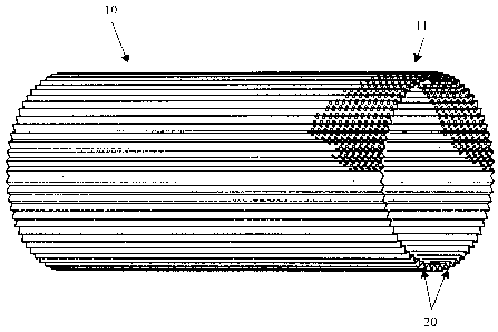
Figure 1 shows the insert 10 with perforations 11 and triangular insert
profiles 20.
Figure 2 shows the insert 10 insitu with perforations 11 muffler housing 12
muffler
packing 13 and insert profiles 20
Figure 3 shows the insert 10 with perforations I lmuffler packing 13 and
insert profiles
20.
Figure 4 shows the insert 10 with perforations 11 muffler housing 12 muffler
and insert
profiles 20
Figure 5 shows insert 10 with perforations 11 muffler packing 13 with
variation on the
insert profile shape 20.

CA 02593100 2007-05-30
DETAILED DESCRIPTION OF THE PREFERRED EMBODIMENT
The preferred embodiment, a muffler insert generally identified by reference
numeral 10,
will now be described with reference to FIGS. 1, 2, 3, 4, and 5.
Structure and Relationship of Parts
The resonance muffler consists of the insert with a specific profile shape to
be located in
a muffler housing that has no sound absorption materials. The absorption
muffler consists
of the insert with a specific profile shape to be located in a muffler housing
and
surrounded or encased by sound absorption materials.
Referring to FIG. 1, there is provided a perforated insert with a specific
profile to be used
in either absorption style or resonance style mufflers.
Referring to FIG. 2 there is provided a perforated insert with a specific
profile located in
an absorption muffler housing encased with sound absorption materials.
Referring to FIG.3 there is provided a perforated insert with a specific
profile located in
an absorption muffler housing encased with sound absorption materials.
Referring to FIG.4 there is provided a perforated insert with a specific
profile to be
located in an absorption muffler housing.
Referring to FIG. 5 there is provided a perforated insert with a specific
profile located in
an absorption muffler housing encased with sound absorption materials.

Representative Drawing
A single figure which represents the drawing illustrating the invention.
Administrative Status

2024-08-01:As part of the Next Generation Patents (NGP) transition, the Canadian Patents Database (CPD) now contains a more detailed Event History, which replicates the Event Log of our new back-office solution.

Please note that "Inactive:" events refers to events no longer in use in our new back-office solution.

For a clearer understanding of the status of the application/patent presented on this page, the site Disclaimer , as well as the definitions for Patent , Event History , Maintenance Fee  and Payment History  should be consulted.

Event History

Description Date
Application Not Reinstated by Deadline 2010-05-31
Time Limit for Reversal Expired 2010-05-31
Inactive: Adhoc Request Documented 2010-03-04
Deemed Abandoned - Failure to Respond to Maintenance Fee Notice 2009-06-01
Application Published (Open to Public Inspection) 2008-11-30
Inactive: Cover page published 2008-11-30
Inactive: First IPC assigned 2007-10-09
Inactive: IPC assigned 2007-10-09
Inactive: Filing certificate - No RFE (English) 2007-08-08
Application Received - Regular National 2007-08-03
Small Entity Declaration Determined Compliant 2007-05-30

Abandonment History

Abandonment Date Reason Reinstatement Date
2009-06-01

Fee History

Fee Type Anniversary Year Due Date Paid Date
Application fee - small 2007-05-30
Owners on Record

Note: Records showing the ownership history in alphabetical order.

Current Owners on Record
JASON SWIST
Past Owners on Record
None
Past Owners that do not appear in the "Owners on Record" listing will appear in other documentation within the application.
Documents

To view selected files, please enter reCAPTCHA code :


To view images, click a link in the Document Description column (Temporarily unavailable). To download the documents, select one or more checkboxes in the first column and then click the "Download Selected in PDF format (Zip Archive)" or the "Download Selected as Single PDF" button.

List of published and non-published patent-specific documents on the CPD .

If you have any difficulty accessing content, you can call the Client Service Centre at 1-866-997-1936 or send them an e-mail at CIPO Client Service Centre.


Document
Description 
Date
(yyyy-mm-dd) 
Number of pages   Size of Image (KB) 
Abstract 2007-05-29 1 14
Description 2007-05-29 4 146
Claims 2007-05-29 2 55
Drawings 2007-05-29 5 128
Representative drawing 2008-11-03 1 22
Cover Page 2008-11-23 1 45
Filing Certificate (English) 2007-08-07 1 157
Notice: Maintenance Fee Reminder 2009-03-02 1 120
Courtesy - Abandonment Letter (Maintenance Fee) 2009-07-26 1 172
Second Notice: Maintenance Fee Reminder 2009-11-30 1 118
Notice: Maintenance Fee Reminder 2010-03-01 1 122
Correspondence 2007-08-23 1 11