Note: Descriptions are shown in the official language in which they were submitted.
CA 02593242 2007-07-05
WO 2006/074420
PCT/US2006/000579
TITLE
LOW PROFILE EXHAUST HOOD
BACKGROUND AND PRIOR ART
[Para 1] Basic exhaust hoods use an exhaust blower to create a negative
pressure zone
to draw effluent-laden air directly away from the pollutant source. In kitchen
hoods, the
exhaust blower generally draws pollutants, including room-air, through a
filter and out of the
kitchen through a duct system. An exhaust blower, e.g., a variable speed fan,
contained
within the exhaust hood is used to remove the effluent from the room and is
typically
positioned on the suction side of a filter disposed between the pollutant
source and the
blower. Depending on the rate by which the effluent is created and the buildup
of effluent
near the pollutant source, the speed of exhaust blower may be manually set to
minimize the
flow rate at the lowest point which achieves capture and containment.
[Para 2] Hoods are intended to act as buffers which match the flow of
fumes, which
varies, to the constant rate of the exhaust system. But basic hoods and
exhaust systems are
limited in their abilities to buffer flow. The exhaust rate required to
achieve full capture and
containment is governed by the highest transient load pulses that occur. This
requires the
exhaust rate to be higher than the average volume of effluent (which is
inevitably mixed with
entrained air). Ideally the oversupply of exhaust should be minimized to avoid
wasting
energy. Hoods work by temporarily capturing bursts of effluent, which rise
into the hood due
by thermal convection and then, giving the moderate average exhaust rate time
to catch up.
[Para 31 One problem with the buffer model is that the external environment
my
displace filmes and thereby add an excess burden of-ambient air into-the
exhaust stream. -This
results in fumes being injected into the occupied space surrounding the hood.
These
transients are an on-going problem for hood design and installation. all the
effluent by
buffering the and containment by providing a buffer zone above the pollutant
source where
buoyancy-driven momentum transients can be dissipated before pollutants are
extracted. By
managing transients in this way, the effective capture zone of an exhaust
supply can be
increased.
CA 02593242 2012-07-20
[Para 4] US Patent No. 4,066,064 shows a backshelf hood with an exhaust
intake
located at a position that is displaced from a back end thereof. A short
sloping portion
rises and extends at a shallow angle toward the inlet from the back end o f
the hood
recess.
[Para 5] US Patent No. 3,941,039 shows a backshelf hood with side skirts
and
sloping wall from a rear part of the hood to an inlet located near the middle
of the hood.
The front of the hood as a horizontal portion (baffle) that extends between
about 15
percent and about 20 percent of the front to back dimension of the hood. This
part is
claimed to direct air in a space above the baffle toward the exhaust inlet and
to direct air
that is drawn from the ambient space in a horizontal direction thereby
encouraging rising
fumes to be deflected toward the exhaust inlet.
SUMMARY OF THE INVENTION
[Para 5a] The present invention seeks to provide an improved exhaust hood
apparatus in view of the art noted and described above.
[Para Sb] In a first aspect, the present invention provides an exhaust
apparatus,
comprising: a pair of symmetrically arranged hoods linked by a horizontal duct
and
connected to a frame for mounting on a conveyor oven such that the hoods are
positioned
directly above, respectively, inlet and outlet trays of said conveyor over.
[Para 5c] In a further aspect, the present invention provides a exhaust
apparatus for
a conveyor oven, which has a bounding external surface with conveyor trays
extending
in a horizontal direction therefrom, the exhaust apparatus comprising: a first
hood linked
to a duct at a first end thereof and connected to a frame configured for
mounting on the
conveyor oven such that the first hood is positioned directly over a conveyor
tray of the
conveyor oven; the first hood having a recess defined at least in part by an
interior wall,
the hood interior wall having a first side, a second side opposite to the
first side, a bottom
edge, a top edge, and opposing side edges, the hood interior wall bottom edge
being
arranged proximal to a top of the conveyor oven and over an access located in
the
bounding external surface of said conveyor oven when the first hood is mounted
on the
conveyor oven; the hood interior wall being angled such that the top edge is
farther from
- 2 -
CA 02593242 2012-07-20
the access than the bottom edge and such that the hood interior wall defines a
piecewise-
continuous surface with the bounding external surface when the first hood is
mounted on
the conveyor oven, the hood interior wall further defining a first hood
exhaust inlet at the
top edge, the exhaust inlet being configured to convey fumes to an exhaust
system
through said duct, the first hood having at least one grease filter disposed
such that fumes
on the first side of said hood interior wall flow through said exhaust inlet
to said second
side of said hood interior wall and into said at least one grease filter.
[Para 5d1 In yet a further aspect, the present invention provides an
exhaust hood
comprising: a top wall; a front wall extending in a vertical direction from a
front edge of
the top wall; and a filter support panel arranged under the top wall in the
vertical
direction and spaced from the front wall in a horizontal direction, the filter
support panel
being angled such that a bottom edge of the filter support panel remote from
the top wall
is farther in the horizontal direction from the front wall than a top edge of
the filter
support panel proximal to the top wall, the filter support panel being
constructed to retain
a grease filter therein, wherein the top wall, front wall, and filter support
panel define a
recess of the exhaust hood, and a lower portion of the front wall is convexly
curved such
that a bottom edge of the front wall is closer to the filter support panel in
the horizontal
direction than the front edge of the top wall.
BRIEF DESCRIPTION ON THE DRAWINGS
[Para 6] Fig. 1 shows a low profile exhaust hood in partial section view.
[Para 7] Fig. 2 shows the exhaust hood of Fig. 1 in perspective view.
[Para 8] Fig. 3 shows the exhaust hood of Figs. 1 and 2 in operative
association
with a stack of conveyor ovens.
[Para 9] Fig. 4 illustrates a modular structure for mounting the foregoing
embodiments of hoods on a stack of conveyor ovens.
[Para 10] Fig. 5 illustrates another embodiment of a low profile exhaust
hood.
- 2a -
CA 02593242 2012-07-20
[Para 11] Fig. 6 illustrates a flow transition feature that may be used for
applications
of the foregoing embodiments.
[Para 12] Fig. 7 illustrates a backshelf hood embodiment.
[Para 13] Figs. 8-12 illustrate variations on the embodiment of Fig. 7.
[Para 14] Figs. 13A-13C illustrate a canopy hood embodiment.
- 2b -
CA 02593242 2007-07-05
WO 2006/074420
PCT/US2006/000579
[Para 1 5] Figs. 14 and 15 illustrate features associated with mounting a
filter.
[Para 1 6] Figs. 16A and 16B illustrate a retractable radiation and
convection shield.
[Para 1 7] Fig. 17 illustrates features of the inventive embodiments.
DETAILED DESCRIPTION OF THE EMBODIMENTS
[Para 1 8] An eyebrow-type exhaust hood (also called a cap or vent cowl-
type hood) may
be used above a door or opening such as a pizza, conveyor oven, bakery oven,
broiler,
steamer. This type of hood overhangs an access opening for the oven or similar
equipment
and captures thermal plumes that flow upwardly from the access opening. The
capture zone
is generally at least as wide as the opening. The depth may vary with some
designs being
shallower than the face of the appliance. Such hoods may be mounted directly
on the
appliance. Conveyor ovens can project forward of the oven mouth such that the
hood may or
may not overhang the source of effluent. This type of hood may also be used
for conveyor
washers, sintering ovens, and other sources of hot effluent.
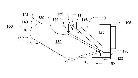
[Para 1 9] Referring to Figs. 1 and 2, an eyebrow hood 100 is shown in
cross-section.
The hood 100 has a recess 130 defined by sidewalls 142 and a top 140 which
covers up to a
forward edge 141 thereof. A back of the recess 130 is defined by a forward
filter support
plate 115 with openings 116 to permit the flow of exhaust effluent into a
plenum 125 and
supports (the supports are not shown) to support filter cartridges 110 in the
openings 116. A
baffle plate 120 is connected to the filter support plate 115 by a hinge 122.
The hinge 122
allows the baffle plate 120 to be dropped down to the position indicated at
122 to allow the
filter cartridges 116 to be removed and installed.
= [Para 2 0] A grease-trough 170-co11ects grease from the filter
cartridges 1-10. The angle-
of the baffle plate 120 with respect to the filter support plate 115 defines a
flow transition 135
leading to the faces of the filter cartridges 110. The position of the baffle
plate 120 also
defines a slot 135, indicated by the double arrow, through which the effluent
stream is drawn
by an exhaust system (not shown) connected to the plenum 125 by an exhaust
collar 105.
The baffle plate 120 also defines a sloping rear planar boundary of the recess
130.
- 3 -
CA 02593242 2007-07-05
WO 2006/074420
PCT/US2006/000579
[Para 21] Referring now also to Fig. 3, the eyebrow hood 100 is shown
mounted to a
stack of conveyor ovens 220. Each conveyor oven 220 has inlet and outlet
conveyor
terminals 225 and 230 which extend beyond respective oven mouths (not visible
in the side
view) located at the ends 231 and 232 of the ovens 220.
[Para 22] Hot gasses escape from the ends 231 and 232 as well as from
material carried
on the conveyor terminals 225 and 230. The latter may be open to the flow of
gasses
allowing plumes, indicated by arrows 210, to rise through the conveyor
terminals. Some
plumes, such as indicated at 205, may flow around the conveyor terminals 225
and 230.
Plumes rising close to the ends 231 and 232 tend to stay close to the ovens
220 due to the
Coanda effect (or wall flow) so that some of the fumes will tend to flow along
the baffle plate
120 until sucked into the slot 135.
[Para 23] Plumes rising further away from the ovens 220 will tend to be
captured in a
suction zone (not indicated separately) around the slot 135. The forward edge
141, which
drops downwardly, defines a shallow canopy that helps to buffer and capture
flow that is
further away from the ovens 220. A common exhaust duct 260 connects the
collars 105 of
the two eyebrow hoods 100 and leads them to a further common duct 150 that is
connected to
an exhaust fan (not shown).
[Para 24] By locating the slot 135 in a position remote from the walls 231
and 232 of the
ovens 220, a suction zone is defined remote from the ovens 220 to capture fume
plumes, such
as 205, which rise remote from the ovens 220. Additionally, the baffle plate
120 provides an
inclined, partially vertical surface along which plumes closer to the ovens
220, such as 206,
may cling and thereby be guided to the slot 135. This configuration allows
filters to be
located conveniently close to the exhaust collar 105 at a rear end of the
eyebrow hood 100.
The remotely located suction zone allows the reach of the hood 100 to be
extended and its
capture efficiency is equivalent to a larger conventional hood with a deeper
and more
extended canopy.
[Para 25] Referring now to Fig. 4, a configuration similar to that of Fig.
3 is shown. A
bracing structure 365 of angle brackets 320 and 325 supports the eyebrow hoods
100. The
bracing structure 365 allows the hoods 100 to rest on top of the ovens 220 and
be connected
to them. A common duct 335 may be combined with the bracing structure 365 to
form a
- 4 -
CA 02593242 2007-07-05
WO 2006/074420
PCT/US2006/000579
unitary device for mounting the hoods 100. This unitary device may be
conveniently
disconnected from a building's exhaust system and moved with the ovens 220
rather than
installed and left as part of the building's permanent facilities.
[Para 26] Referring now to Fig. 5, an eyebrow hood 400 is shown in cross-
section. The
hood 100 has a recess 430 defined by sidewalls 442 and a top 440 which covers
up to a
forward edge 441 thereof. A back of the recess 430 is defined by a forward
filter support
plate 415 with openings 416 to permit the flow of exhaust effluent into a
plenum 425 and
supports (the supports are not shown) to support filter cartridges 410 in the
openings 416. A
baffle plate 420 is connected to the filter support plate 415 by a hinge 422.
The hinge 422
allows the baffle plate 420 to be dropped down to the position indicated at
422 to allow the
filter cartridges 416 to be removed and installed.
[Para 271 A grease trough 470 collects grease from the filter cartridges
410. The angle
of the baffle plate 420 with respect to the filter support plate 415 defines a
flow transition 435
leading to the faces of the filter cat tlidges 410. The position of the
baffle plate 420 also
defines a slot 435 through which the effluent stream is drawn by an exhaust
system (not
shown) connected to the plenum 425 by an exhaust collar 405. The baffle plate
420 also
defines a sloping rear planar boundary of the recess 430. In the present
embodiment, the slot
435 is extended by en extended portion 421, which in this case is horizontal.
The baffle plate
420 may also, in an alternative configuration, be flat but inclined at an
angle less than that
shown in Fig. 1 to extend the slot 435.
[Para 28] Referring now to Fig. 6, an eyebrow hood 400 protects an oven 470
such as a
pizza oven. A mouth of the oven 475 is well below the eyebrow hood 400 proper.
A baffle
extension plate 452 bridges a gap between the mouth 475 and a baffle plate
420. In other
respects, the configuration of Fig. 5 is like that of Figs. 1 and 2. The
presence of the baffle
extension plate 452 provides for a smooth wall-transition to which thermal
plumes may
attach and rise toward the slot 135 without the turbulence-inducing effect of
abrupt edges, for
example as indicated at 472, as might otherwise be present in the Coanda flow
path.
[Para 29] Referring now to Fig. 7, the principles behind the eyebrow hood
of the
foregoing figures can be extended to backshelf hoods such as indicated at 500.
A canopy
portion 510 extends over a cooking process 525 defining, in cooperation with a
baffle plate
- 5 -
CA 02593242 2007-07-05
WO 2006/074420
PCT/US2006/000579
518 and filter support plate 514, a plenum 520, a manifold 530, and a recess
535. An inlet
slot 515 draws fumes from the cooking process 525 from a forward part of the
recess 535
creating a suction zone near the front of the hood 500 which is indicated by
arrays of arrows
566A and 566B. Side skirts 545 may protect the ends of the hood, in the
dimension going
into and out of the drawing plane.
[Para 301 As in the eyebrow hood of Figs. 1 and 2, the baffle plate 518
provides a
surface to which thermal plumes, as indicated at 560, may attach and rise
toward the inlet slot
515. Plumes generated closer to the forward end of the hood 500, such as
indicated at 565,
rise in a plug flow that is independent of any surface, but proximate the
suction zone 566A,
566B of the inlet slot 515. By locating the inlet to the exhaust close to the
forward edge of
the hood 500, a suction zone is created close to the forward edge which helps
to prevent the
escape of thermal plumes near the forward edge.
[Para 31] Referring to Figs. 8 through 12, a common coordinate system with
respect to
the plane of the drawing page is illustrated in Fig. 8. In the normal reading
position, the y-
axis is left to right, the z-axis is up and down, and the x-axis goes into the
drawing plane
directly away from the reader. Referring now particularly to Fig. 9, a curved
baffle plate 615
rises from a back wall plane 616 up to an inlet slot 630. A hood 610A defines,
in conjunction
with a filter support plate 626 and the baffle plate 615, a plenum 606, a
header chamber 601,
and a recess 607. An exhaust opening 620 connects the plenum 606 to an exhaust
system
(not shown). Side skirts 650 may also be provided. This embodiment differs
from that of
Fig. 7 in having a smoothly curving baffle plate 615 rather than a flat one
and also in the
precise matching of the baffle plate 615 surface and that of the back wall
616. Either of these
features may be provided independent of the others. Note that a forward edge
605A of the
hood 610A drops down only as far as the inlet slot 630. In this arrangement,
the suction zone
in front of the hood 610A is maximized. Also note that the forward access 632C
is high due
to an absence of the more typical deep recess of a conventional hood design.
[Para 32] Referring now to Fig. 10, an embodiment similar to that of Fig. 9
is shown.
The present embodiment has a more extended forward edge 605B of the hood 610B
compared to the embodiment of Fig. 9. The extended edge 605B increases the
capacity of a
recess 608 compared to that of recess 607 of Fig. 9. The increased size of the
recess allows a
greater buffering effect and reduces the height forward access 632B. The lower
height of the
- 6 -
CA 02593242 2007-07-05
WO 2006/074420
PCT/US2006/000579
forward access increases mean velocity through the forward access region. The
configuration
of Fig. 10, with the increase recess volume may be more suited to lower
temperature or lower
moisture effluent sources to sources which produce more variable fume plumes
in terms of
the distribution along the x-axis or in terms of time.
[Para 33] Referring now to Fig. 11, an embodiment similar to that of Fig.
10 is shown.
In the present embodiment, the inlet slot 675, although in a substantially
forward position, is
moved, compared to the previous to embodiment, toward the rear. This has the
effect of
focusing the suction zone downwardly and rendering it somewhat less diffuse.
The more
middle position may be used in combination with any of the foregoing features.
It has been
determined to be more suitable for applications where there are fewer external
disturbances to
disrupt the rising plumes from the cooking process 640.
[Para 34] Also illustrated in the present embodiment is a spoiler 618. The
spoiler 618
spreads any Coanda plumes in the x-axis direction so that a fast moving
pulsatile thermal
plume is less likely to flow past the inlet slot 675. Essentially, it is a
mechanism for
transverse (x-direction) mixing of the z-*y-direction momentum that is tangent
to the surface
of the baffle 615 (or, put another way, the transverse mixing of the component
of the flow
along this surface's gradient). Paradimatically, a transient plume that is
localized with respect
to the x-axis may overwhelm the suction capacity of the inlet slot 675 at a
particular point
along x. If such a plume is spread across the x-axis by turbulent mixing, its
locally high
velocity may be reduced and the resulting wider (and slower) plume may be more
easily
handled by the suction of the inlet slot 675. The spoiler may be provided with
or without
other features and in combination with any of the foregoing features discussed
in connection
with this or the other embodiments to the same effect.
[Para 35] Referring to Fig. 12, an alternative to the use of a spoiler,
such as spoiler 618
in Fig. 11, which may have a similar effect, is to make the attachment
surface, that of the
baffle plate 680, convex in shape. This reduces the volume of the recess 611
but it increases
the resistance to plug flow formation and forces plumes to tend to spread
across the surface of
the baffle plate 680. In the present embodiment, the forward edge of the hood
610D also
curves toward the inlet slot 695.
- 7 -
CA 02593242 2007-07-05
WO 2006/074420
PCT/US2006/000579
[Para 36] Referring now to Figs. 13A-13D, a canopy style hood 700 has an
exhaust
outlet 730 and an exhaust inlet slot 705 that surrounds the entire canopy 711.
Flow guide
plates 720 having the form of a pyramidoid or conoid structure run from a low
point 721 up
to the inlet slot 705. A filter support structure 712 supports filters 710 and
defines a plenum
714 connecting flow through the filters 710 to the exhaust outlet 730. The
flow guide plates
may be provided with a door (not shown) to allow access to the filters 710.
[Para 37] Referring now to Figs. 14 and 15, some alternative ways of
arranging a filter
in combination with a forwardly located exhaust inlet while maintaining a
compact
configuration and a relatively narrow (and therefore, high velocity) intake,
are illustrated. In
a hood 800 of Fig. 14, a hatch, shown in a closed configuration at 804 and
open at 805
provides access to a filter 810 mounted on a plenum 820. Fumes from an
appliance 830 flow
through an inlet 815 into a header space 811, through the filter 810, into
plenum 820 and out
through an exhaust outlet 825. As in previous embodiments, a sloping flow wall
823 runs
from the rear toward the front and upwardly to allow fume plumes to attach. A
side skirt 822
may be provided to mitigate end effects. In a hood 890 of Fig. 15, two hatches
850 and 885
are provided, the hatch 850 shown in a closed configuration at 850 and open at
851. The
hatches 850 and 885 provide access to a filter 810 mounted on a plenum 821.
Fumes from an
appliance 830 flow through an inlet 865 into a header space 875, through the
filter 810, into
plenum 821 and out through an exhaust outlet 872. As in previous embodiments,
a sloping
flow wall 853 runs from the rear toward the front and upwardly to allow fume
plumes to
attach. A side skirt 852 may be provided to mitigate end effects.
[Para 38] Referring to Figs. 16A and 16B, a retractable curtain 910 of heat
resistant
reflective material is drawn from a spool 900 down to cover the sides of stack
of ovens 220.
The configuration is not unlike that of a home movie screen, permitting the
curtain 910 to be
easily retracted out of the way. A weighted bar 915 keeps the bottom of the
curtain in place.
Alternatively, a curtain (not shown) may be made of rigid material and placed
in a similar
position. Also, the curtain 910 need not be drawn all the way down. The
curtain 910 reduces
the air flow required for containment and capture by acting as a convection-
inhibiting side
curtain. It also increases comfort by reducing radiation to the surrounding
space. Finally, the
curtain 910 also reduce heat loss of the oven so the oven's energy consumption
is reduced.
Variations of the curtain may be provided to achieve these benefits. For
example, rigid
- 8 -
CA 02593242 2007-07-05
WO 2006/074420
PCT/US2006/000579
panels (not shown) that pivot on a vertical axis may be mounted to swing over
the sides of the
hoods 100 without covering the oven 220 sides.
[Para 39] It will be observed that various features have been described in
connection
with the foregoing embodiments. These features may be combined in combination
and
various subcombinations. As can be seen in Figs. 1 to 3, the exhaust inlet is
located as high
as possible in a low profile hood 1005 by employing the baffle plate 120 as
illustrated. The
inlet 135 is defined between the top of the hood 143 and the edge of the
baffle. As may be
seen in other embodiments, the baffle may have an opening while still
providing a high
location for the inlet.
[Para 40] As shown in Fig. 17, the baffle 120 (and similarly for the other
embodiments)
also is aligned to form a substantially continuous wall surface 1000 (shown by
the heavy line
which is superimposed on the oven/hood combination) extending from the face of
the oven
1010 to the baffle portion 1120 leading up to the inlet 1030. Because the
ovens 220 are hot
and because fumes escaping from them are hot, they tend to rise aggressively
along the
surface and also due to the wall-flow (Coanda flow) effect, this continuous
surface helps to
guide much of the fumes directly to the inlet 1030. At the same time, the
inlet 1030 is
located remotely from the oven to create a suction zone positioned to capture
rising fumes
that are deflected away from the surface 1000 by ambient gusts or by food
items on the
conveyor shelves 225. Still further, a lip 1050 is defined to create a small
buffer volume
between the inlet and the lip 1050 of the hood 1005 to help ensure containment
when fume
loads are irregular.
[Para 41] Still another feature of the Fig. 17 design and other embodiments
is the low
profile of the hood 1005, which in preferred embodiments, is wider than it is
high. This is
advantageous because the overhead clearance for such ovens as 220 may be
limited. Also,
the side skirts 1015 are taller close to the ovens 220 but narrow toward the
lip 1050 to
provide greater clearance for workers needing to stand close to the ovens 220
to access the
loading and/or unloading trays 225.
[Para 421 The above features may be employed in subcombinations. For
example, the
continuous wall 1000 may be provided in other configurations, for example,
with an inlet
located lower than the top of the hood 1005 or without side skirts 1015 or lip
1050. For
- 9 -
,
CA 02593242 2007-07-05
WO 2006/074420
PCT/US2006/000579
another example, the low aspect-ratio hood design may have more conventional
structures
such as ones that do not provide the continuous surface 1000; i.e., baffle 120
(Fig. 1) 1020
removed.
- 10 -