Note: Descriptions are shown in the official language in which they were submitted.
CA 02593584 2007-07-13
1
Coffee machine having a dispenser with independent heating
Background of the Invention
The present invention relates to a coffee machine having a
dispenser provided with independent heating and to a method
for preparing coffee in accordance with said machine.
Coffee (the beverage) has always been very widespread and
popular; in fact, nowadays it is available in a number of
varieties which differ from each other both in terms of the
starting mixture and in terms of the means of extraction
(temperature and time of extraction, quantity of water used,
etc. ) .
The automated preparation of coffee has been the subject of
a number of developments, substantially directed towards
ensuring that water could always be available, at the
desired time, at the ideal temperature, at the required
pressure and in the necessary quantities.
Among the most recent developments, it is certainly possible
to include the machine described in patent application
EP1074210. That machine comprises a dispenser which is
connected to the boiler by way of a means for controlling
the thermosiphon circulation and can be controlled both so
as to dispense coffee of the Mediterranean type (obtained
with from 15 to 25 ml of water at approximately 98 C which
passes through the mixture of ground coffee for
approximately 30 seconds), and so as to dispense cafe creme
(obtained from light blends, in which from 100 to 120 ml of
water at approximately 90 C are caused to flow in
approximately 20 seconds through the ground coffee) which is
more widespread in northern Europe.
CA 02593584 2007-07-13
2
Changing over from one control type to the other, however,
requires long and complex operations to be carried out for
calibrating the control valve which, precisely owing to the
length thereof, cannot be carried out during daily use of
the machine in a bar or in another public place.
Currently, machines possess an ever greater number of
functions and an ever increasing proportion of those is
electronically controlled, affording the operators the
possibility of using ad hoc programmes for an ever
increasing number of different services and/or beverages.
The increasing availability around the world of espresso
coffee has led to an increase in the demand for variety and
quality of the beverages.
Objects and Summary of the Invention
It is an object of the present invention to provide a coffee
machine having greater flexibility than that of machines
known in the art so that it is also possible to produce, on
the same machine, different types of coffee, even as
alternatives, without this involving a diminution in the
quality of the coffee produced or any long waiting times for
the start-up and calibrating operations.
In order to achieve that greater flexibility, the applicant
has developed a system for controlling the dispensing of the
water which always ensures the correct temperature of the
water, independently of the type of coffee which is
requested.
CA 02593584 2007-07-13
3
Detailed Description of the Preferred Embodiment
The features and advantages of the present invention will
become clear from the following detailed description of one
practical embodiment, given purely by way of non-limiting
example with reference to the single Figure, in which there
are schematically represented a hydraulic circuit and a
control circuit for a coffee machine in accordance with an
embodiment of the present invention.
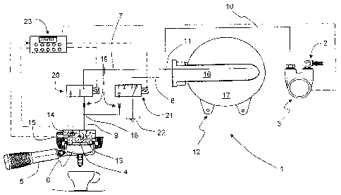
The Figure shows a cup, in which hot coffee is poured from
the spout of an infusion unit 5, which is fixed in known
manner to a dispensing unit 13.
The coffee machine comprises, at the inner side thereof, a
hydraulic circuit, generally designated 1, which in turn
comprises inlet means 2 which connect the hydraulic circuit
1 to a suitable source of water, for example, the water
mains, which is generally at low temperature (2 - 20 C).
The coffee machine is further provided with connections for
electrical energy and, generally, at least one pump 3 which
is arranged upstream of the hydraulic circuit 1 in the
immediate vicinity of the inlet means 2.
The coffee machine comprises, at the opposite end of the
hydraulic circuit 1 relative to the inlet means 2, a
dispensing portion 4, through which the water at temperature
is dispensed into an infusion unit 5 which defines the
infusion chamber 6 and is generally constructed by means of
an element that is separate from the coffee machine but
which can be fixedly joined thereto.
CA 02593584 2007-07-13
4
The inlet means 2 and the dispensing portion 4 are placed in
fluid communication with each other by at least one cold
water pipe 7 and one hot water pipe 8.
The cold and hot water pipes coincide along an end portion 9
which terminates in the dispensing portion 4; in the event
that the inlet means 2 comprise a single inlet for mains
water which is common to the cold water and hot water pipes,
the pipes coincide in an initial portion 10 in the region of
the inlet means 2, too.
In that case, represented in the Figure, the hydraulic
circuit 1 comprises suitable flow division elements 11 to
passively subdivide and/or actively control the ratio
between the flow of water of the portions of cold water pipe
7 and hot water pipe 8 which are arranged downstream.
The cold water pipe 7 places the dispensing portion 4 in
fluid communication with the inlet means 2, without
providing any specific element for varying the temperature
of the water which flows through it.
The hot water pipe 8, however, comprises heating means 12
which are capable of substantially increasing the
temperature and/or the pressure of the water which flows
inside the hot water pipe 8 itself.
The heating means 12 are upstream of the dispensing portion
4 and downstream of the flow division elements 11 which,
when present, separate the flow portion which will have to
be heated from that which will not have to be heated.
CA 02593584 2007-07-13
The dispensing portion 4 and at least a portion of the end
portion 9 are constructed inside the dispensing unit 13,
which serves to bring about engagement with the infusion
unit 5 and direct the flow of water at temperature from the
dispensing portion 4 so that it can pass through the
infusion chamber 6, extracting the coffee flavours in the
most homogeneous manner possible.
The temperature of the dispensing unit 13 must be maintained
as close as possible to the temperature of the water which
flows in the end portion 9 so that the temperature of the
water is not subjected to variations owing to the thermal
differential with respect to the dispensing unit 13 when it
flows therein.
In this manner, it is possible to ensure a high level of
quality of the coffee produced by the machine.
In order to ensure that the dispensing unit 13 can be
maintained at the desired temperature, that is, in order to
compensate for the heat losses owing to dissipation in the
external environment, a heat generator 14, which is separate
from the heating means 12 which are interposed upstream of
the hot water pipe 8, is provided inside the dispensing unit
13.
The heat generator 14 therefore takes the place of the
function which, in thermosiphon circulation machines, was
carried out directly by the hot water which flowed inside
the dispensing unit 13.
The heat generator 14 can advantageously be a resistor,
preferably connected to the main electrical power supply of
the coffee machine in such a manner that the electrical
CA 02593584 2007-07-13
6
power consumed by it is subtracted from the electrical power
available for the other consumes.
Since the electrical power consumed by the electrical mains
network depends only on the heat dissipated, the electrical
power consumed by the heat generator 14 in order to heat the
dispensing unit 13 does not have to be consumed by the
heating means 12 in order to heat that portion of water
which, previously, was used in order to indirectly heat the
dispensing unit 13.
In that manner, it becomes possible to install a new machine
in place of an old one without having to modify the
electrical system of the premises in which the old machine
was installed.
The dispensing unit 13 also comprises a temperature sensor
15 which can generate a signal indicating the temperature of
the dispenser itself.
The dispensing unit 13 is constructed from thermally
conductive material, preferably metal.
The heating means 12 advantageously comprise a heat
exchanger 16 which is fitted in the boiler 17 of the
machine; alternatively, they can be constituted by the
boiler 17 itself which receives cold water from the initial
portion 10 of the hot water pipe.
Therefore, the exchanger 16 receives heat from the boiler 17
and heats the water contained in the cold water pipe 8 up to
a temperature Tc. The temperature Tc is selected so as to
allow a high level of efficiency of the boiler 17 and is
CA 02593584 2007-07-13
7
generally between 110 C and 125 C so that the machine can
always be provided with hot water for any requirement.
The cold water pipe 7 remains separate from the hot water
pipe 8 as far as a mixing location 18, which defines the
start of the end portion 9.
Upstream of the mixing location 18, there are provided, both
in the cold water pipe 7 and in the hot water pipe 8,
respective chokes 19 for controlling the flow rates and,
upstream thereof, there are provided a first valve 20 and a
second valve 21, respectively; those valves can
advantageously be constituted by solenoid valves.
The second valve 21 can advantageously be connected
downstream of the heating means 12 and, in the event that it
is a three-way valve, it can also be connected to an outlet
22 in order to discharge the residual pressure downstream
thereof, in the hot water pipe 8 and/or from the end portion
9.
The machine also comprises control means 23 which are
connected to the heat generator 14 and/or the temperature
sensor 15 and/or each of the valves 20, 21 and/or the pump 3
in such a manner as to receive therefrom the signals and/or
to control each of them.
In that manner, they can receive the signal which is
representative of the temperature of the dispensing unit 13
from the temperature sensor 15 and consequently control the
heat generator 14 in order to increase, if necessary, the
temperature of the dispensing unit 13 up to the desired
value.
CA 02593584 2007-07-13
8
The valves 20 and 21 can, for example, be controlled by the
control means 23 so as to allow the passage of pulses of
cold water in the cold water pipe 7 and pulses of hot water
in the hot water pipe 8, respectively.
At the same time, the connection of the control means 23 to
the valves 20 and 21 allows control of the flow of the cold
water pipe 7 and hot water pipe 8, respectively, and
therefore control of the temperature of the water which
flows downstream of the mixing location 18 inside the end
portion 9.
The coffee machine can advantageously also comprise a
selector (not illustrated in the Figure), for example, a
rotary selector or a push-button type selector, which allows
the operator to select the programme in accordance with
which the coffee is to be prepared.
That selector is connected to the control means 23 in order
to determine the manner in which they must interpret the
data received in order to control the valves 20 and 21
and/or the heat generator 14 and/or the pump 3.
Two possible operating modes of the coffee machine will be
described below in accordance with an embodiment of the
present invention and will show how the temperature of the
dispensing unit 13 can be rapidly and effectively increased
or decreased in the event that it is not already the
temperature required for preparing a coffee of the desired
type.
Considering, for example, the step for preparing a
Mediterranean coffee: higher temperature, smaller flows of
water and smaller volumes with respect to cafe creme.
CA 02593584 2007-07-13
9
In that case, when the operator acts on the selector, for
example, by pressing the push-button corresponding to
Mediterranean coffee, the control means 23 verify that the
temperature of the dispensing unit 13 corresponds to that
provided for by the programme; if the temperature is too
low, a signal is transmitted to the heat generator 14 which
heats the dispensing unit 13 until it reaches the correct
temperature.
Valves 20 and 21 are controlled in such a manner that,
downstream of the mixing location 18, in the end portion 9,
the temperature of the water corresponds to that required
for Mediterranean coffee.
In this manner, water and dispensing unit 13 have the same
temperature and the water is not subjected to any variation
in temperature during its passage through the dispensing
unit 13.
Since the temperature must be the correct one not so much at
the start of the end portion 9 but rather inside the
infusion chamber 6, it is clearly possible to set the
programmes of the control means 23 in such a manner that
both the temperature of the mixed water at the start of the
end portion 9 and the temperature of the dispensing unit 13
are such that the optimum temperature of the water is
obtained inside the infusion chamber 6. This requires only
simple initial calibration operations which can readily be
carried out once for each type of coffee.
Optionally, it is also possible to combine the heating
effect produced by the heat generator 14 with the heating
effect produced by the water which passes through the end
CA 02593584 2007-07-13
portion 9: by suitably controlling the valves 20 and 21, it
is possible, knowing the temperature of the dispensing unit
13 and the structural parameters, to select the temperature
of the water in such a manner that it is slightly hotter
when it passes through the dispensing pipe 15 than would be
necessary.
In that manner, during the passage through the dispensing
pipe 15, the water imparts heat to the dispensing unit 13,
bringing about the dual effect of reaching the correct
temperature for preparing the coffee and accelerating the
heating of the dispensing unit 13 itself.
The control means 23 advantageously comprise means for
dynamically determining the temperature of the water which
must be conveyed in the end portion 9 both in accordance
with the type of beverage which has to be prepared (that is,
the necessary flow, volume and temperature of water) and in
accordance with the design specifications of the machine
(thermal inertia values of the elements in which the water
flows, passage times, measured temperature, instantaneous
electrical power of the heat generator 14, etc.).
In this manner, it is possible to convey to the end portion
9 water which, at the beginning of the step for preparing
the coffee, is slightly hotter and, consequently, as the
dispensing unit 13 gradually becomes hotter, to reduce the
temperature of the water conveyed to the end portion 9 until
it reaches the correct operating temperature.
The valves 20 and 21 can be adjusted so as to determine with
precision the ratio between the flow of hot water and the
flow of cold water.
CA 02593584 2007-07-13
11
Advantageously, it is possible to provide additional
temperature sensors (not illustrated) which are arranged
both in the cold water pipe 7 and in the hot water pipe 8 so
as to provide the control means with the necessary
information for even more precise adjustment of the
operational timing of the valves 20, 21 and more precise
adjustment of the final temperature of the water which flows
downstream of the mixing location 18 inside the end portion
9.
In the event that, after a Mediterranean coffee, it is
desired to prepare a type of coffee which requires a lower
temperature, for example, a cafe creme, it might be
necessary to cool the dispensing unit 13 in order to prevent
it from excessively heating the infusion water.
When the operator sends the command to prepare the cafe
creme, the control means 23, on the basis of the programming
data, measure the temperature of the dispensing unit 13 and
convey water at a temperature that is slightly lower than
the optimum temperature so that, when the water comes into
contact with the dispensing unit 13, it receives the
necessary heat therefrom in order to reach the correct
temperature, at the same time cooling the dispensing unit
13.
In that case, it is also possible to carry out dynamic
control of the temperatures: the structural parameters being
known, in accordance with the variation in temperature of
the dispensing unit 13, the control means 23 will
advantageously be able to operate the valves 20 and 21 in
such a manner that the water which flows in the end portion
9 has a variable temperature, so as to acquire the heat
which the dispensing unit 13 is able to impart thereto, in
CA 02593584 2007-07-13
12
order always to reach the infusion chamber 6 at the same
correct temperature.
These functional examples have described the means by which
it is possible to adjust the temperature of the dispensing
unit 13 by acting both on the heat generator element 14 and
on the dynamic mixing of the flows of water, controlled by
the valves 20 and 21.
Naturally, a person skilled in the art, for the purposes of
satisfying contingent and specific requirements, may apply a
number of modifications and variants to the above-described
configurations without, however, departing from the scope of
protection of the invention as defined by the appended
claims.