Note: Descriptions are shown in the official language in which they were submitted.
CA 02593932 2007-07-10
WO 2006/084213 PCT/US2006/004009
1
PROCESS FOR BLOW-MOLDING A CONTAINER COMPRISING A HANDLE
The present invention relates to a process of stretch blow molding preforms in
a mold
cavity. The present invention is concerned with a process for the manufacture
of
containers comprising handles, especially bottles in excess of about 2 litres
capacity, for
which handles are highly desirable.
EP-A-O 346 518, published on 20th December 1989, discloses an injection
stretch blow
molding process for the production of bottles with integral handles. The
process
comprises the steps of stretching a preform within a mold cavity by axial
stretching
with a stretch pin; and transverse stretching with blown air; and pressing and
holding an
area of the stretched preform between a pair of opposed moveable projecting
members
which move in a direction which is perpendicular to the axial movement of the
stretch
pin.
However this process requires the further step of thermally fusing the
peripheral edges
of the opposing depression and removing the resin inside the peripheral edges
in order
to form the handle.
The problem remains to provide a process of stretch blow molding in a mold
cavity to
provide a container having an integral handle without the need to fuse the
inner walls of
the container, and without the need to subsequently remove the sealed portions
to create
the handle in the container, a process called de-flashing. A clear advantage
of a process
that does not require sealing and then de-flashing is that it does not require
using a
material which is readily fusable. Further, it does not affect the integrity
of the preform,
and hence allows to provide a container that is not prone to leakage or
breakage.
Further, such a container will not have any sharp edges in the handle area
which it is
difficult to avoid when two sealed surfaces are cut through.
Another problem which remains- is to provide a simpler mold with only one
moving
segment compared to the two opposite moving segments described in the prior
art.
CA 02593932 2007-07-10
WO 2006/084213 PCT/US2006/004009
2
Summary of the Invention
The present invention relates to a process for blow-molding a container, the
container
comprising a handle, whereby the process comprises the steps of:
(i) introducing a preform into a mold cavity and stretching the prefornl with
a stretch
rod;
(ii) increasing the pressure within the preform so that the preform expands
within the
mold cavity;
(iii) displacing at least one further moving section within the mold to deform
the
thermoplastic material;
and wherein the displacement of the moving section is in a direction which is
substantially parallel to the direction of movement of the stretch rod.
Steps (i) and (ii) may take place in any order, or simultaneously.
Brief Description of the Drawings
Figure 1 a shows a perspective view of a preform which is suitable for use in
the present
invention. Figure lb shows a cut-away section of a mold with the stretched and
expanded preform therein.
Figure 2a shows a perspective view of an alternative embodiment of the present
invention. Figure 2b shows a side elevation of this alternative embodiment.
Figure 3a shows a side elevation of another alternative embodiment of the
present
invention. Figure 3b shows a perspective view of this alternative embodiment.
Figure 4a shows a perspective view of another alternative embodiment of the
present
invention. Figure 4b shows a side elevation of this alternative embodiment.
CA 02593932 2007-07-10
WO 2006/084213 PCT/US2006/004009
3
Figure 5a shows a perspective view of an alternative embodiment of the present
invention. Figure 5b shows a cut-away section of the mold in the handle region
of this
alternative embodiment. Figure 5c illustrates the cut off of the tail.
Figure 6a shows a perspective view of an alternative embodiment, using cams,
of the
present invention. Figure 6b shows a side elevation of this alternative
embodiment.
Figure 7a shows a perspective view of an alternative, asymmetric, preform
which is
suitable for use in the present invention. Figure 7b shows a cut-away section
of a bottle
formed therefrom.
Figure 8 illustrates another alternative of the present invention.
Detailed Description of the Invention
Transparent containers, such as bottles, are highly desirable packages for
consumer
goods such as drinks, foodstuffs, laundry and household cleaning products,
shampoo
and other personal care products.
It is also desirable that relatively large packages, for example 2 liters and
above, should
be provided with a handle so that the consumer can conveniently lift the
product and
pour from the package even when the package is full.
Suitable containers for consumer goods are typically blown in a molding
process.
A "mold" as described herein generally comprises two or more parts which can
be
closed to form a "mold cavity", and opened in order to allow a preform to be
inserted
into the mold and/or the blown product to be removed from the mold. Additional
moving elements within the mold cavity are referred to herein as "moving mold
sections".
CA 02593932 2007-07-10
WO 2006/084213 PCT/US2006/004009
4
In commercial operations multiple mold cavities may be combined in a
continuous,
high-speed machine.
By "preform" what is meant herein is a molded form which is produced prior to
expansion to form the finished object. A preform is necessarily somewhat
smaller than
the finished object. A preform is made from a thermoplastic material and is
generally
produced by, for example injection molding, at an elevated temperature in
excess of the
melt temperature of the thermoplastic material.
By "stretch blow-molding" or "SBM" what is meant herein is a process in which
the
preform is first stretched longitudinally, generally by means of a stretch rod
or plunger,
followed by a blowing step at a temperature above the glass transition
temperature,
designed to result in retained orientation in the blow direction so that the
resulting
configuration is "biaxially oriented". Stretch blow molding is a highly
desirable process
to manufacture bottles, especially bottles for consumer goods. The SBM process
stretches and orients the thermoplastic material and allows to make bottles
with highly
desirable mechanical properties, especially clarity, mechanical strength (top
load) and
high resistance to impacts such as impacts occurring if the filled or partly
filled bottle is
dropped on to a hard surface.
Transparent containers are made from various materials, notably thermoplastic
materials, and most commonly with polyethylene terephthalate (PET). Other
materials
suitable for use in the present invention are polypropylene (PP), polyethylene
(PE),
polyvinyl chloride (PVC) and polylactic acid (PLA). Polypropylene is
particularly
preferred. Polypropylene is readily available in commercial grades. Materials
having
suitable combinations of melt strength, re-heat properties, clarity and
processing
window size are available from suppliers such as Borealis, BP, and Total, e.g.
Total's
PPR7225.
The present invention relates to a stretch blow-molding process which provides
a
transparent container with a-handle without requiring any secondary welding or
deflashing process. In the present invention a moving section within the mold
deforms
CA 02593932 2007-07-10
WO 2006/084213 PCT/US2006/004009
the preform in a direction substantially parallel, and preferably opposing,
the direction
of movement of the stretch rod. This creates a minor cavity that is linked to
the major
cavity at just one end. This cavity is then filled with material via blow gas,
and forins a
handle section.
5
According to the present invention the movable mold section is displaced
within the
mold in a direction which is substantially parallel to the direction of
movement of the
stretch rod. Compared to the process of using two opposite moving segments
which
move in a direction perpendicular to the direction of movement of the stretch
rod, as
described in the prior art, the process of the present invention has the
advantage of
simplifying the mold design and construction, and furthermore facilitates
higher speeds
of operating the process. The displacement of the moving mold section as
described
herein can be better understood with reference to a series of orthogonal axes,
x, y, z, in
which the x axis is defined herein as the direction of movement of the stretch
rod.
However, the moveable mold section, moving in three dimensions, may also be
displaced in the y and z axes (i.e. in the y-z plane), as well as in the x
axis as defined
above. By "substantially parallel" in the context of the present invention it
is preferred
that the acute angle formed between the y-z plane and the direction of travel
of the tip
of the moving mold section whilst in contact with the preform or expanding
container is
at least 30 , more preferably the angle is at least 45 , still more preferably
it is at least
600
, and most preferably it is at least 75 .
In one embodiment of the present invention, the movable mold section deforms
the
expanding or expanded preform.
In an alternative embodiment of this invention, the movable mold section
contacts the
side of the preform during or after the stretch rod axially stretches the
preform but
before blow gas further expands the preform. This causes material to be held
at an area
above the contact point which is then blown into the minor cavity to form the
handle.
This alternative process enables more material to be used for the handle
formation
giving greater strength and dimensional stability.
CA 02593932 2007-07-10
WO 2006/084213 PCT/US2006/004009
6
Since this process requires significant deformation of the preform in order to
achieve
the desired end result, use of asymmetric preforms, preferential heating
techniques and
specific mold coatings may be desired in order to ease the distribution of
material
within the mold to render the process more efficient and reliable.
Preferred embodiments of the invention is described in more detail herein
below with
reference to the drawings.
Figure 1 a shows a standard shaped preform 2. The preform 2 may be fabricated
by any
known technique including injection molding, extrusion blow-molding or
compression
molding. This preform 2 is either re-heated to an appropriate molding
temperature, or is
already at this temperature after cooling from the injection-molding step of a
1-stage
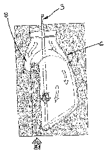
ISBM machine. In Figure lb, the preform is introduced into a mold cavity 6
that
contains a moveable mold section 4. A stretch rod 3 is then introduced into
the hot
preform 2 and used to longitudinally stretch the material. At or before the
point when
the rod 3 contacts the base of the preform 2, high pressure blow-gas is
applied to the
inside of the preform 2, forcing the preform 2 to expand into the vented mold
cavity 6.
The movable mold section 4 is initially retracted.
As the preform 2 expands and its walls thin, the movable mold section 4 moves
within
the mold 6, stretching material inwards towards the centre, and creating a
cavity behind.
Material will then be forced into this minor cavity 8, forming the handle.
Further blow
gas will then be applied to the inside of the preform at higher pressure than
the initial
gas, forcing the preform to completely fill the cavity 8.
Figure 2 is a variation of Fig. 1 b wherein the moving mold section 14 has
been split into
two half revolving segments which assist in formation of the minor cavity 17.
This has
the advantage that the stresses applied to the material can be reduced.
Figure 3 show another embodiment of the present invention in which a moving
mold
section 24 moving along the same axis as the stretch rod 23, and in the same
direction
CA 02593932 2007-07-10
WO 2006/084213 PCT/US2006/004009
7
as the stretch rod 23. This helps to better stretch the material in the minor
cavity 27 as
the material is both pushed and pulled at the same time.
Figure 4 shows another embodiment of the present invention wherein the moving
mold
section 34 pulls the handle. The moving mold section 34 has an undercut to
better grip
the material for pulling into the minor cavity 37.
Figure 5 shows an alternative method of assisting the moving mold section 44
mentioned above by means of a "pulling" segment, wherein the pulling segment
has a
pinch grip to catch the edge 49 of the preform to efficiently pull it into the
minor cavity
47.
Figure 6 shows another embodiment of the present invention wherein a pair of
cams 64
are rotated so as to form the minor cavity 67, and hence to fornz the handle.
Figure 7a shows a preform 102 which is an alternative to the preform of Figure
1 a. In
Figure 7a the material distribution of the preform 102 is asymmetric.
Figure 7b shows a cut-away section of a container formed from the preform of
Figure
7a.The container comprises a handle disposed on a side of the bottle. This
makes the
container different from containers without handle and also from containers
with
clipped on handles, both of which are typical of containers produced by the
SBM
process. The handle is joined to the side of the container by a merging
region. The
handle according to the invention is, for example, forming a recess in the
generally
vertical direction when the bottle is standing upright upon its base, the
recess being such
that a user may slide the hand in the recess to hold, lift and pour from the
container.
Figure 8 shows a moving mold section 84 contacting the side of the preform 82
after
axial stretch by the stretch rod 83 but before pre-blow. The handle is formed
by the
minor cavity 87.