Language selection

Search

Patent 2594062 Summary

Third-party information liability

Some of the information on this Web page has been provided by external sources. The Government of Canada is not responsible for the accuracy, reliability or currency of the information supplied by external sources. Users wishing to rely upon this information should consult directly with the source of the information. Content provided by external sources is not subject to official languages, privacy and accessibility requirements.

Claims and Abstract availability

Any discrepancies in the text and image of the Claims and Abstract are due to differing posting times. Text of the Claims and Abstract are posted:

  • At the time the application is open to public inspection;
  • At the time of issue of the patent (grant).
(12) Patent: (11) CA 2594062
(54) English Title: OIL STRAINER FOR A GAS TURBINE ENGINE
(54) French Title: CREPINE A HUILE POUR TURBINE A GAZ
Status: Deemed expired
Bibliographic Data
(51) International Patent Classification (IPC):
  • F02C 7/06 (2006.01)
  • F01D 25/18 (2006.01)
(72) Inventors :
  • DUROCHER, ERIC (Canada)
  • LEFEBVRE, GUY (Canada)
(73) Owners :
  • PRATT & WHITNEY CANADA CORP. (Canada)
(71) Applicants :
  • PRATT & WHITNEY CANADA CORP. (Canada)
(74) Agent: NORTON ROSE FULBRIGHT CANADA LLP/S.E.N.C.R.L., S.R.L.
(74) Associate agent:
(45) Issued: 2015-02-17
(22) Filed Date: 2007-07-19
(41) Open to Public Inspection: 2008-02-22
Examination requested: 2012-07-13
Availability of licence: N/A
(25) Language of filing: English

Patent Cooperation Treaty (PCT): No

(30) Application Priority Data:
Application No. Country/Territory Date
11/466,162 United States of America 2006-08-22

Abstracts

English Abstract

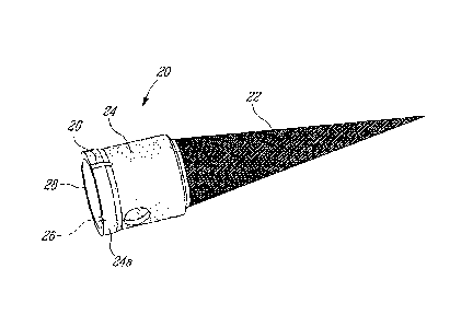
The oil strainer has a filtering portion and a flexible sleeve portion to which the filtering portion is connected. The flexible sleeve portion has a plurality of spigot- receiving slots on the upstream side of the strainer.


French Abstract

La crépine à huile présente une partie filtration et une partie manchon souple à laquelle la partie filtration est reliée. La partie manchon souple présente une pluralité de fentes destinées au logement de robinets sur le côté amont de la crépine.

Claims

Note: Claims are shown in the official language in which they were submitted.


6
WHAT IS CLAIMED IS:
1. An oil strainer assembly for use in a gas turbine engine, the gas
turbine engine
including an oil tube coupling having a conduit portion, a shoulder portion
inside the conduit
portion and at least one spigot projecting inside the conduit portion at a
location upstream the
shoulder portion, the assembly comprising an oil strainer insertable into a
seat formed by the
conduit portion, the shoulder portion and the at least one spigot, the oil
strainer including a
flexible sleeve portion with at least one slot configured and disposed to
receive the
corresponding at least one spigot when the oil strainer is fully seated.
2. The oil strainer assembly as defined in claim 1, wherein the flexible
sleeve portion has
an enlarged rim resting against a corresponding shoulder in the conduit
portion.
3. A method of installing an oil strainer in a corresponding oil tube
coupling provided in a
gas turbine engine, the oil strainer including a flexible sleeve portion, the
method comprising:
flexing the flexible sleeve portion; and
pushing the oil strainer into a fully seated position where one end of the
flexible sleeve
portion abuts a shoulder portion inside the oil tube coupling and an opposite
end of the flexible
sleeve portion has at least one slot to receive a corresponding spigot
projecting from inside the
oil tube coupling.

Description

Note: Descriptions are shown in the official language in which they were submitted.


CA 02594062 2007-07-19

1
OIL STRAINER FOR A GAS TURBINE ENGINE
TECHNICAL FIELD

The invention relates to an oil strainer, and in particular to an improved oil
strainer for use in a pressurized oil circuit of a gas turbine engine.

BACKGROUND
Oil strainers are generally used to prevent solid debris larger than a certain
size
from reaching a device to which the oil is provided, for instance a bearing.
In the
past, oil strainers used in gas turbine engines typically included a machined
ring
welded to a mesh. The oil strainers were held in their seat using a removable
fastener, such as a snap ring. Oil strainers must maintain a leak-tight seaf
with
their seat to prevent unfiltered oil from by-passing them, which leak would
potentially result in some solid debris reaching the device. A leak may also
occur
if the strainer is re-installed in its seat without the proper orientation
during
maintenance.

Overall, it was desirable to provide an improved oil strainer that is simple
to
manufacture and to install in its seat.

SUMMARY
In one aspect, the present concept provides an oil strainer for a gas turbine
engine, the oil strainer having an upstream side and a downstream side, and
comprising a filtering portion and a flexible sleeve portion to which the
filtering
portion is connected, the flexible sleeve portion having at least one spigot-
receiving slot on the upstream side of the strainer.

In another aspect, the present concept provides an oil strainer assembly for
use
in a gas turbine engine, the gas turbine engine including an oil tube coupling
having a conduit portion, a shoulder portion inside the conduit portion and at
least one spigot projecting inside the conduit portion at a location upstream
the
DOCSMTL: 2442241 \1


CA 02594062 2007-07-19

2
shoulder portion, the assembly comprising an oil strainer insertable into a
seat
formed by the conduit portion, the shoulder portion and the at least one
spigot,
the oil strainer including a flexible sleeve portion with at least one slot
configured
and disposed to receive the corresponding at least one spigot when the oil
strainer is fully seated.

In a further aspect, the present concept provides a method of installing an
oil
strainer in a corresponding oil tube coupling provided in a gas turbine
engine, the
oil strainer including a flexible sleeve portion, the method comprising:
flexing the
flexible sleeve portion; and pushing the oil strainer into a fully seated
position
where one end of the flexible sleeve portion abuts a shoulder portion inside
the
oil tube coupling and an opposite end of the flexible sleeve portion has at
least
one slot to receive a corresponding spigot projecting from inside the oil tube
coupling.

Further details of these and other aspects of the improved oil strainer will
be
apparent from the detailed description and figures included below.

BRIEF DESCRIPTION OF THE FIGURES

For a better understanding and to show more clearly how it may be carried into
effect, reference will now be made by way of example to the accompanying
figures, in which:

FIG. 1 schematically shows a generic gas turbine engine to illustrate an
example
of a general environment in which the improved oil strainer can be used;

FIG. 2 is a perspective view of an example of an improved oil strainer; and

FIG. 3 is a cross-sectional view showing an example of an oil tube coupling in
which the improved oil strainer of FIG. 2 is installed.


CA 02594062 2007-07-19

3
DETAILED DESCRIPTION

FIG. 1 illustrates a gas turbine engine 10 of a type preferably provided for
use in
subsonic flight, generally comprising in serial flow communication a fan 12
through which ambient air is propelled, a multistage compressor 14 for
pressurizing the air, a combustor 16 in which the compressed air is mixed with
fuel and ignited for generating an annular stream of hot combustion gases, and
a
turbine section 18 for extracting energy from the combustion gases. FIG. 1
only
shows one example of the general environment in which the improved oil
strainer
can be used. The improved oil strainer can be used with other turbofan models
or other kinds of gas turbine engines, such as turboprop or turboshaft
engines.
Referring now to FIG. 2, there is shown an example of an oil strainer 20 as
improved. This oil strainer 20 includes a filtering portion 22 and a flexible
sleeve
portion 24 to which the filtering portion 22 is connected. The oil strainer 20
is
also preferably symmetrical around a central axis.

In the embodiment illustrated in FIG. 2, the filtering portion 22 is somewhat
funnel-shaped and projects in direction of the downstream side, thus the same
direction as the oil flows. The flexible sleeve portion 24 can be made of
using a
thin metallic sheet shaped as reqiaired.

The flexible sleeve portion 24 has a plurality of spigot-receiving slots 26 on
the
upstream side 28 of the oil strainer 20. These slots 26 are designed to
maintain
the connection between the oil strainer 20 and spigots provided in an oil tube
coupling when the oil strainer 20 is fully seated. In the illustrated
embodiment,
the slots 26 are only at the outer surface of the flexible sleeve portion 24.
They
can also be from one side of the flexible sleeve portion 24 to another. Also,
the
upstream side 28 of the oil strainer 20 is enlarged in the illustrated
embodiment.
The slots 26 are two in number and are opposite each other. The slots 26 have
a
substantially rectangular cross section.


CA 02594062 2007-07-19

4
FIG. 3 shows the oil strainer 20 of FIG. 2 when fully seated in an oil tube
coupling 30. The expression "oil tube coupling" generically and broadly refers
to
a location of the pressurized oil circuit where an oil strainer can be used in
a gas
turbine engine. The illustrated oil tube coupling 30 comprises a conduit
portion
32 and a shoulder portion 34 inside the conduit portion 32. Spigots 36 are
provided inside the conduit portion 32. The number of slots 26 in the flexible
sleeve portion 24 is equal to the number of spigots 36. There is thus two
spigots
36 opposite each other with reference to the conduit portion 32. The spigots
36
have a substantially rectangular cross section and a portion of the spigots 36
is
attached within the oil tube coupling 30.

In use, to install the oil strainer 20, the flexible sleeve 24 portion is
slightly
inwardly flexed so as to pass between the spigots 36. The edge of the flexible
sleeve portion 24 on the downstream side will eventually reach the shoulder
portion 34 of the oil tube coupling 30. The oil strainer 20 is shaped to abut
against the shoulder portion 34 of the oil tube coupling 30 while the radial
spigots
36 are set into their respective slots 26 once the oil strainer 20 is fully
inserted
into its seat. The flexible sleeve portion 24 is designed to have a tight fit
inside
the conduit portion 32. The friction generated between the flexible sleeve
portion
24 and the conduit portion 32 increases the retention of the oil strainer 20.
The
slots 26 may also be sized to have a tight fit with the spigots 36 so as to
create
additional friction between them in the resulting assembly.

In the illustrated embodiment, the upstream side 28 of the oil strainer 20 has
an
enlarged external rim 24a that rests against a corresponding front shoulder
38.
The above description is meant to be exemplary only, and one skilled in the
art
will recognize that other changes may also be made to the embodiments
described without departing from the scope of the invention disclosed as
defined
by the appended claims. For instance, the present invention is not limited to
oil
strainers used with bearings. The strainer can be located upstream another
kind
of device, such us a pump, a valve, etc. The oil strainer can have a different


CA 02594062 2007-07-19

shape than the model illustrated herein. In particular, the shape of the
filtering
portion can vary greatly from what is shown. The oil strainer is not
necessarily
symmetrical around the central axis. For instance, some oil strainers can be
somewhat oval or have asymmetrical slots to accommodate asymmetrical
5 spigots. The number of spigots can be only one or be more than two. Also,
the
spigots are not necessarily identical or located at the same axial position in
the
same oil tube coupling. Still other modifications which fall within the scope
of the
present invention will be apparent to those skilled in the art, in light of a
review of
this disclosure, and such modifications are intended to fall within the
appended
claims.

Representative Drawing
A single figure which represents the drawing illustrating the invention.
Administrative Status

For a clearer understanding of the status of the application/patent presented on this page, the site Disclaimer , as well as the definitions for Patent , Administrative Status , Maintenance Fee  and Payment History  should be consulted.

Administrative Status

Title Date
Forecasted Issue Date 2015-02-17
(22) Filed 2007-07-19
(41) Open to Public Inspection 2008-02-22
Examination Requested 2012-07-13
(45) Issued 2015-02-17
Deemed Expired 2020-08-31

Abandonment History

There is no abandonment history.

Payment History

Fee Type Anniversary Year Due Date Amount Paid Paid Date
Registration of a document - section 124 $100.00 2007-07-19
Application Fee $400.00 2007-07-19
Maintenance Fee - Application - New Act 2 2009-07-20 $100.00 2009-07-10
Maintenance Fee - Application - New Act 3 2010-07-19 $100.00 2010-07-19
Maintenance Fee - Application - New Act 4 2011-07-19 $100.00 2011-07-05
Maintenance Fee - Application - New Act 5 2012-07-19 $200.00 2012-05-15
Request for Examination $800.00 2012-07-13
Maintenance Fee - Application - New Act 6 2013-07-19 $200.00 2013-04-19
Maintenance Fee - Application - New Act 7 2014-07-21 $200.00 2014-06-16
Final Fee $300.00 2014-11-19
Maintenance Fee - Patent - New Act 8 2015-07-20 $200.00 2015-06-26
Maintenance Fee - Patent - New Act 9 2016-07-19 $200.00 2016-06-21
Maintenance Fee - Patent - New Act 10 2017-07-19 $250.00 2017-06-21
Maintenance Fee - Patent - New Act 11 2018-07-19 $250.00 2018-06-20
Maintenance Fee - Patent - New Act 12 2019-07-19 $250.00 2019-06-21
Owners on Record

Note: Records showing the ownership history in alphabetical order.

Current Owners on Record
PRATT & WHITNEY CANADA CORP.
Past Owners on Record
DUROCHER, ERIC
LEFEBVRE, GUY
Past Owners that do not appear in the "Owners on Record" listing will appear in other documentation within the application.
Documents

To view selected files, please enter reCAPTCHA code :


To view images, click a link in the Document Description column. To download the documents, select one or more checkboxes in the first column and then click the "Download Selected in PDF format (Zip Archive)" or the "Download Selected as Single PDF" button.

List of published and non-published patent-specific documents on the CPD .

If you have any difficulty accessing content, you can call the Client Service Centre at 1-866-997-1936 or send them an e-mail at CIPO Client Service Centre.


Document
Description 
Date
(yyyy-mm-dd) 
Number of pages   Size of Image (KB) 
Abstract 2007-07-19 1 6
Description 2007-07-19 5 196
Claims 2007-07-19 2 43
Drawings 2007-07-19 2 70
Representative Drawing 2008-02-13 1 26
Cover Page 2008-02-13 1 50
Claims 2014-04-10 1 29
Representative Drawing 2015-01-28 1 21
Cover Page 2015-01-28 1 45
Assignment 2007-07-19 6 202
Prosecution-Amendment 2012-07-13 2 69
Prosecution-Amendment 2014-04-10 3 114
Prosecution-Amendment 2013-10-18 2 61
Correspondence 2014-11-19 2 68