Note: Descriptions are shown in the official language in which they were submitted.
CA 02594113 2008-09-24
Carbon Nanotube Composites for Blade Cleaning in
Electrophotographic Marking Systems
Field
[001] This invention relates to an electrophotographic marking system
process and more specifically to a photoconductor cleaning blade system
useful in said process.
Cross Reference
[002] In U.S. Publication No. 2006-0292360 filed on June 28, 2005
presently pending in the U.S. Patent and Trademark Office, a fuser or fixing
members for use in a photosensitive marking system are disclosed. This
fuser member includes a substrate where the coating layer comprises carbon
nanotubes dispersed in a polymeric binder material. Also disclosed in U.S.
Publication No. 2006-0292360 is an electrostatic printing apparatus using this
fusing and fixing member.
[003] U.S. Publication No. 2006-0292360 and the present application,
ID 20052195, are both owned by the present assignee, Xerox Corporation.
I
CA 02594113 2007-07-19
Background
[004] In marking systems such as Xerography or other electrostatographic
processes, a uniform electrostatic charge is placed upon a photoreceptor
surface.
The charged surface is then exposed to a light image of an original to
selectively
dissipate the charge to form a latent electrostatic image of the original. The
latent
image is developed by depositing finely divided and charged particles of toner
upon the photoreceptor surface. The charged toner being electrostatically
attached to the latent electrostatic image areas creates a visible replica of
the
original. The developed image is then usually transferred from the
photoreceptor
surface to a final support material, such as paper, and the toner image is
fixed
thereto to form a permanent record corresponding to the original.
[005] In some Xerographic copiers or printers, a photoreceptor surface is
generally arranged to move in an endless path through the various processing
stations of the xerographic process. Since the photoreceptor surface is
reusable,
the toner image is then transferred to a final support material, such as
paper, and
the surface of the photoreceptor is prepared to be used once again for the
reproduction of a copy of an original. In this endless path, several
Xerographic
related stations are traversed by the photoconductive belt.
[006] Generally, in one embodiment, after the transfer station, a
photoconductor cleaning station is next and it comprises a first cleaning
brush, a
second cleaning brush and after the brushes are positioned, a spots or
cleaning
blade which is used to remove residual debris from the belt such as toner
additive
and other filming. This film is generally caused by the toner being impacted
onto
the belt by the cleaning brushes. When the lubrication of this blade is below
a
2
CA 02594113 2007-07-19
necessary level, it will abrade the belt. Toner is the primary lubricant for
the
blade; however, a problem is with good cleaning efficiency by the cleaning
brushes, the amount of toner reaching the blade can often be well below this
necessary level. Without proper lubrication, this spots blade will seriously
abrade
the beit.
[007] Since most toners used today are negatively charged, the
embodiments throughout this disclosure and claims will be described relating
to
the use of a negative toner; however, when a positive toner is used, the
proper
opposite adjustments can easily be made.
[008] The first brush above mentioned in prior art systems is responsible
for nearly all of the filming on the photoconductive (PC) belt. This brush is
positively charged to attract a negative charged toner and remove most of it
from
the PC belt. Adjacent to the first brush is a vacuum which vacuums the toner
from the brush for later disposal. Any toner that may have acquired a positive
charge will pass by the first positively charged brush and will be picked up
by the
second brush which is negatively charged. The vacuum is also adjacent to the
second brush and should vacuum off the brush any residual positively charged
toner. Then, as above noted, the spots or cleaning blade scrapes off the belt
any
remaining toner debris or film layer. Again, after the action of the two prior
cleaning brushes there is generally not sufficient toner lubrication for an
effective
action by this spots blade. The cleaning blade will remove the film layer
comprised of toner additives that is caused by the impact of the first brush
against the toner and PC belt. The serious problem that has been encountered
in this type of prior art arrangement is, as noted, that the cleaning blade
does not
3
CA 02594113 2007-07-19
get enough toner provided lubrication and can easily scratch and damage the
belt, causing a relatively high replacement rate for both the belt and the
cleaning
blade. In addition, copy quality begins to deteriorate as the cleaning blade
is
abraded and damaged or as the film is less effectively removed from the PC
belt
by this blade.
[009] Many of the low volume electrophotographic printers and some high
speed marking apparatus use elastic doctor blades to remove residual toner
from
drum or belt photoreceptors. Improvements in the reliability of such blades
are
desired to minimize/reduce wear induced defects and to extend the overall life
of
the cleaning blade. Unloaded polyurethane and other elastomeric materials are
typically useful in cleaning blade materials. Improved materials are required
to
extend the useful life of such blades.
Summary
[010] The present embodiments involve the incorporation of carbon
nanotubes in electrophotographic cleaning blades, said blades consisting of
polyurethane or other suitable elastomeric matrix materials. Carbon nanotubes
can be formed by a variety of known methods including carbon arc discharge,
pulsed laser vaporization, chemical vapor deposition and high pressure CO.
Other methods are discussed in the articles cited in paragraph [014] below.
Examples of suitable elastomer materials include, but are not limited to,
polyurethanes, organic rubbers such as ethylene/propylene diene, fortified
organic rubbers, various copolymers, block copolymers, copolymer and
elastomer blends, and the like. It is proposed that a small percentage of
carbon
4
CA 02594113 2007-07-19
nanotubes or even loadings up to 60% by weight can improve the robustness of
the material without significant compromising the elastomeric properties.
Thus,
improvements in the latitude to defects caused by nip tucking that can induce
tears in the blade edge is envisioned, as well as overall life extension for
ultimate
blade failure. Furthermore, addition of carbon nanotubes to the blades can
significantly increase their electrical conductivity as well as the thermal
conductivity. This enhanced electrical conductivity can dissipate charge
accumulation at the blade due to rubbing against the photoreceptor and air
breakdown from the accumulation of charged toner at the blade edge. The
enhanced thermal conductivity can aid heat dissipation due to friction at the
blade-photoreceptor interface. Carbon nanotubes (CNT) represent a new
molecular form of carbon in which a single layer of atoms is rolled into a
seamless tube that is on the order of 1 to 10 nanometers in diameter and up to
hundreds of micrometers in length. (1) Multi-walled nanotubes (MWNT) were
first
discovered by lijima of NEC Labs in 1991. Two years later, he discovered
single-
walled nanotubes (SWNT). Since then, nanotubes have captured the attention of
researchers worldwide. The nanotubes can be either conducting or semi-
conducting, depending on the chirality (twist) of the nanotubes. They have
yield
stresses much higher than that of steel, and can be kinked without permanent
damage. The thermal conductivity of CNT is much higher than that of copper,
and comparable to that of diamond. The nanotubes can be fabricated by a
number of methods, including carbon arc discharge, pulsed laser vaporization,
chemical vapor deposition (CVD) and high pressure CO. Variants of nanotubes
CA 02594113 2007-07-19
that contain only carbon include nanotubes with equal amounts of boron and
nitrogen.
[011] Recent experiments report a significant increase in the thermal
conductivity of polymers when filled with relatively low volume fractions of
carbon
nanotubes (2). For example, for only a 1% volume fraction of SWNT in epoxy,
the composite thermal conductivity was approximately 0.5Wm 1K-1 which was
more than double the conductivity of the pure epoxy. This increase is
attributed
to the high thermal conductivity of nanotubes, which is believed to be 3000 Wm
1K"' for MWNT (3) and even higher for SWNT (4); from 0.5-60% by weight
loading of nanotubes may be used in the present cleaning blade. The composite
thermal conductivity for a 1% loading is about 30 times less than what one
expects from a model that assumes no thermal resistance at the interfaces
between nanotubes. The disparity between the measurements and expectations
might be due to a number of factors, including the dispersablity of the
nanotubes
in the matrix, a high interface thermal resistance or an altering of the
nanotube
conductivity by interactions with the matrix.
Carbon nanotubes (or nanofibers) dispersed in cleaning blades or spots
blades may be used in electrophotographic systems using cleaning brushes or
the cleaning or spots blades can be used by themselves without cleaning
brushes. Reference to "blades" as used in this disclosure and claims will
include
both cleaning blades and spots blades. Spots blades are used to remove films
on the photoconductive surface that the cleaning brushes don't remove. The
carbon nanotubes may be randomly and/or oriented in the elastomer of the
blade. These nanotubes may be dispersed throughout the entire blade or may
6
CA 02594113 2007-07-19
be dispersed primarily at the bottom portion or bottom edge of the blade. This
is
because the bottom portion which contacts the photoconductive surface and
experiences wear is the first to be damaged and causes replacement of the
entire
blade. Therefore, for example, in a blade 2 mm thick, the bottom 0.5-1.0 mm
portion might have the greatest concentration of carbon nanotubes. For some
photoreceptors, the surfaces of the photoconductor is being overcoated with
harder materials to provide longer photoconductor lives. Cleaning blade edges
operating on these overcoated photoconductors are worn at higher rates and
result in earlier blade replacements. The blades of this invention make the
blades used on overcoated photoconductors, as well as non-overcoated
photoconductors, much more durable.
[012] Measurements have been obtained at the Johnson Space Center on
the strength and stiffness of a silicone elastomer filled with SWNT (6). The
composite is stronger and stiffer than the unfilled elastomer. The manual
mixing
of 1% SWNT in the silicone increased the tensile strength by 44% and the
elasticity modulus by 75%. The tensile strength and elasticity increased with
higher SWNT loadings of 5% and 10%. By way of this example, it is clear that
the inclusion of nanotubes into polyurethane cleaning blades can alter the
mechanical properties for longer life performance.
[013] Since the aspect ratio (length to diameter ratio) of carbon nanotubes
is so high, the percolation limit (approximately the inverse of the aspect
ratio) for
electrical conductivity is much iower than typical conductive fillers such as
carbon
black. From Ref. 2 the percolation limit for the addition of SWNT in epoxy is
between only 0.1 to 0.2 wt%. For higher loadings, the conductivity increases
by a
7
CA 02594113 2007-07-19
factor of 104. Hyperion Catalysis, Inc. produces MWNT composite materials for
a
variety of applications that require conductive polymeric materials. It should
be
understood that the proposal to utilize carbon nanotube fillers in
polyurethane
and similar elastomeric materials for cleaning blades can provide significant
performance advantages.
[014] The following articles (whose contents are incorporated herewith)
discuss various aspects of carbon nanotubes: (1) Oeulette J The Industrial
Physicist, American Institute of Physics, Dec. 2002/Jan. 2003 18-21; (2)
Biercuk,
M.J. et al. Carbon nanotube composites for thermal management Appl. Phys.
Lett. 80, 2767-2769 (2002); (3) Berber. S. et al. Unusually high thermal
conductivity of carbon nanotubes, Phys. Rev. Lett. 84, 46134616; (4) Kim. P.
et
al. Thermal transport measurements of individual multiwalled nanotubes, Phys.
Rev. Lett. 87, 215502-1, 215502-4 (2001); (5) Huxtable, S.T. et al.
Interfacial
heat flow in carbon nanotube composites (http://users.mrl.uiuc.edu/cahill/nt-
revised.pdf) and (6) Files BS and Forest CR, Elastomer Filled with Single-Wall
Carbon Nanotubes (http://www.nasatech.com/Briefs/Mar04/MSC23301.html).
[015] Therefore, as earlier stated, the present embodiments involve the
incorporation of carbon nanotubes in elastomeric cleaning blades when said
blades are used in the cleaning stations of electrophotographic marking
systems.
It is provided that a small percentage of carbon nanotubes can improve the
robustness of the material without significantly compromising the elastomeric
properties. Increases in mechanical strength properties reduce blade edge
tears
and substantially extend blade life due to edge wear. Low percentage additions
of carbon nanotubes can also significantly increase electrical and thermal
8
CA 02594113 2007-07-19
conductiveness. Enhanced electrical conductivity can dissipate charge
accumulation at the blade edge due to rubbing against the photoreceptor and
air
breakdown from the accumulation of charged toner at the blade edge. Enhanced
thermal conductivity can aid heat dissipation due to friction at the blade-
photoreceptor interface. Research with nanotubes has shown that mechanical
strength and thermal and electrical conductivities have been achieved at
concentrations of 1% or less by weight. Past experience with the addition of
larger amounts of additives to blade material has often resulted in blades
that
were too stiff to be usable, but the very low concentrations of carbon
nanotubes
required to impact properties avoid this past problem. Included in this
invention
are "carbon nanotubes" which include nanotubes or its variants such as carbon
nanofibers. As the carbon nanotube material, any of the currently known or
after-developed carbon nanotube materials and variants can be used. Thus, for
example, the carbon nanotubes can be on the order of from about 1 to about 10
nanometers in diameter and up to hundreds of micrometers or more in length.
The carbon nanotubes can be in multi-walled forms, or a mixture thereof. The
carbon nanotubes can be either conducting or semi-conducting. Variants of
carbon nanotubes include, for example, nanofibers and are encompassed by the
term "nanotubes" unless otherwise stated. In addition, the carbon nanotubes of
the present disclosure can include only carbon atoms or they can include other
atoms such as boron and/or nitrogen such as equal amounts of boron and
nitrogen. Examples of nanotube material variants thus include boron nitride,
bismuth and metal chalcogenides. Combinations of these materials can also be
used and are encompassed by the term "carbon nanotubes" herein.
9
CA 02594113 2008-09-24
[016] In embodiments, the carbon nanotubes can be incorporated as
a filler into the elastomer layer of a cleaning blade in any desirable and
effective amount. For example, a suitable loading amount can range from
about 0.5 or from about 1 weight percent, to as high as about 50 or 60 weight
percent or more. However, loading amounts of from about 1 or from about 5
to about 20 or about 30 weight percent may be desired in some embodiments.
The composite of the blade is stronger and stiffer than the unfilled
elastomer.
The manual mixing of 1 % by weight of single-walled nanotubes in the
elastomer increased the tensile strength by 44% and the elasticity modulus by
75%. The tensile strength and elasticity modulus further increase with
increased loading amounts of 5% and 10%. An increase in electrical
conductivity helps mitigate the possibility of image distortion or disturbance
by
charge accumulation on the surface of the photoconductor and cleaning
blade.
According to another aspect of the present invention, there is
provided a cleaning blade useful in a cleaning station of an
electrophotographic marking system, said blade consisting of:
an elastomer and from 1-60% by weight of a carbon nanotube,
wherein said elastomer is selected from the group consisting of a
polyurethane, organic rubbers, ethylene diene and propylene diene, fortified
organic rubbers, copolymers, block copolymers, copolymer and elastomer
blends,
said blade comprising said carbon nanotubes having an increased
electrical and thermal conductivity and enabled to enhance the dissipation of
CA 02594113 2008-09-24
accumulated electrical charges at said blade and a photoconductive surface,
and
wherein said carbon nanotubes are selected from the group consisting
of materials containing only carbon atoms, materials containing carbon atoms
and boron, carbon atoms and nitrogen, carbon atoms and bismuth and metal
chalcogenides and wherein said nanotubes are dispersed into said elastomer
and dispersed primarily at a blade location selected from the group consisting
of a bottom edge portion only of said blade, throughout said entire blade, and
only at a front tip portion of said blade.
[017] The blades can be used in the cleaning stations of marking
systems with cleaning brushes (Figures 1 and 2) or in marking systems alone
without cleaning brushes as shown in Figures 3 and 4 of the drawings.
Brief Description of the Drawings
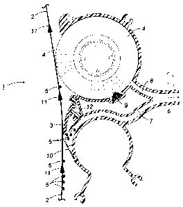
[018] In Figure 1, an embodiment of a marking system using a
cleaning brush and the cleaning blade of this invention is illustrated.
[019] In Figure 2, an embodiment of a marking system using two
cleaning brushes and the cleaning blade of this invention is illustrated.
10a
CA 02594113 2007-07-19
[020] In Figure 3, the elastomeric cleaning blade of this invention (in a
non-brush system) as it contacts a photoreceptor or photoconductive belt is
illustrated. The carbon nanotubes are embedded throughout the elastomer.
[021] In Figure 4, the carbon nanotubes are dispersed primarily on the
front tip of the brush, as illustrated.
[022] In Figure 5, a spots blade is shown for use in a cleaning system of
this invention.
[023] On Figure 6, the carbon nanotubes are dispersed primarily along
the bottom edge of the blade.
11
CA 02594113 2007-07-19
Detailed Discussion of Drawings and Preferred Embodiments
[024] The use of embodiments of the blades of this invention are
described in the following figures:
In Figure 1, cleaning system 1 of an embodiment, a photoconductive belt 2
is shown as it is adapted to move sequentially first to the cleaning blade 3
and
then to an electrostatic brush 4. The elastomeric cleaning blade 3
incorporates
carbon nanotubes, the nanotubes comprising no more than about 60% by weight
of the entire blade. The arrows 11 show the direction and path of the PC belt
2.
The blade 3 is therefore upstream from the brush 4 and is the first cleaning
component that contacts the belt. In this position, blade 3 gets the proper
toner
induced lubrication since toner has not been previously removed by a brush 4
or
any other component. The electrostatic brush 4 has a charge on it that is
opposite to the charge on the toner 5 used in the system. This will permit
brush 4
to attract the opposite charged toner 5 and remove any residual toner 5 not
removed from the PC belt 2 by the cleaning blade 3. As above stated, since the
cleaning blade 3 is the first cleaning component contacted by the belt 2,
there is
sufficient toner 5 on the belt at that point to provide ample lubrication for
the
blade 3 and minimize abrasion of the belt 2. The electrostatic brush 4 in
system
1 follows the blade 3 to remove any residual toner 5. In an embodiment, a
vacuum unit 6 is positioned between the blade 3 and brush 4 to vacuum off any
loose toner removed by either blade 3 and brush 4. After the toner is vacuumed
out it can be disposed of by any suitable method. Vacuum air channels 7 and 8
are in air flow contact with the blade 3 and brush 4, respectively. A flicker
bar 9 is
in operative contact with brush 4 and is adapted to de-tone brush 4 together
with
12
CA 02594113 2007-07-19
vacuum unit 6. As toner 5 is flicked off brush 4 by flicker bar 9, it is
picked up by
the suction of vacuum channel 8 and transported out of system 1. Flicker bar 9
is
positioned such that the fibers in the rotation brush 4 will contact the
flicker bar 9
prior to reaching the vacuum channel 8. In Figure 1, the flicker bar 9 is
shown in
a position consistent with a counterclockwise brush 4 rotation. Clockwise
brush 4
rotation can also be used with the flicker bar 9 in a suitable position. An
entry
shield 10 is located below the cleaning blade 3 and directs loosened toner
into
vacuum channel 7 for removal from system 1. Toner 5, therefore, is
sequentially
removed from photoconductor belt 2 by first contact with blade 3 which scrapes
toner 5 off belt 2 and then by cleaner brush 4 which removes any residual
toner
by brush action together with electrostatic action (since it is biased
oppositely to
toner). The arrows 11 indicate the travel direction of belt 2, blade 3 is
"upstream"
and brush 4 is "downstream" as used in this disclosure. By this continuous
contact with the photoconductive belt 2, the blade 3 in the prior art becomes
worn
and torn at the blade edges which significantly reduces the effective life of
the
blade. With the carbon nanotube containing blades 3 of this invention up to
0.5%
to about 60% by weight, the blade 3 life is significantly increased. The
nanotubes
addition significantly increases the electrical conductivity and thermal
conductivity
of the blade 3. This enhanced electrical conductivity can dissipate charge
accumulation at the blade 3 due to rubbing against the photoreceptor 2. The
enhanced thermal conductivity can aid heat dissipation due to friction at the
blade-photoreceptor interface.
[025] In Figure 2, a second embodiment of the cleaning system
described herein is illustrated. Two brushes 14 and 15 are used and a cleaning
13
CA 02594113 2007-07-19
blade 3 is positioned adjacent to the first brush 14. The first brush 14 is
charged
in a manner that allows ample toner 5 to pass through to the blade tip 3, thus
ensuring adequate lubrication at all times. A negative charge on the first
brush
14 would remove any toner 5 that acquired a positive charge and allow all of
the
negatively charged toner 5 to pass through to the blade tip 3. Alternatively,
a low
positive charge on the first brush 14 would enable some level of cleaning of
negatively charged toner 5 from the PC belt 2, if so desired, depending on the
operating conditions at a given point in time. In either case, positive or
negative
charging of the first brush 14, the charge level would be such that ample
toner is
allowed to pass through to the blade tip 3. The first brush 14 is also used to
transport toner 5 from the blade tip 3 to the vacuum channel 16. Another
vacuum
channel 17 is used to transport any residual loosened toner 5 from the second
brush 15 to a vacuum collection means where it is disposed of. The second
brush 15 can be charged positively or negatively to complement the polarity of
the first brush 14. If the first brush 14 is negative to remove positively
charged
toner 5, the second brush 15 is positive to remove negatively charged toner 5
that was not removed by the blade tip 3. If the first brush 14 is positive to
remove
some negative toner 5, the second brush is negative to remove positively
charged toner 5 that is not removed by the blade tip 3. If the Xerographic
system
is optimized in a manner to ensure only one polarity of toner arrives at the
cleaning system 1, then both brushes 14 and 15 can be charged to the same
polarity, that being opposite of the toner 5 polarity. The charge level on the
first
brush 14 would still be such that an ample amount of lubricating toner 5 would
pass through to the blade tip 3. The flicker bars 18 positions are suitable
for
14
CA 02594113 2007-07-19
brushes that are rotating in a counterclockwise direction. The brush fibers
hit the
flicker bar 18 which compresses the fibers. Then as the fibers open up, they
are
exposed to the vacuum channels 16 and 17 for toner removal. Obviously, if the
brushes 14 and 15 were rotating clockwise, the flicker bars 18 would be shown
in
a different location (preceding the vacuum channels 16 and 17). An entry
shield
is positioned below the first brush 14 to capture loose toner 5 falling from
the
brush 14 or blade 3 of this invention. Unloaded polyurethane is typically used
for
cleaning blade materials. Obviously, other elastomeric materials may be used
if
suitable such as natural or synthetic rubbers. The small percentage of carbon
nanotubes incorporated into the elastomer or polyurethane (either randomly or
in
a pattern) will improve the robustness of the elastomer without significantly
compromising the desired elastomeric properties of blade 3.
[026] In Figure 3, the cleaning blade 3 of an embodiment is shown in an
expanded view as it contacts PC belt 2. In Figure 3 the carbon-nanotube random
distribution with laminated blade is made by centrifugal casting. This blade 3
incorporates carbon nanotubes 19 throughout the elastomer 20 at about 1-60%
by weight. A movable or floating support 12 for the cleaning blade 3 permits
proper movement and support for blade 3 as it contacts PC belt 2. While any
suitable angle of contact 13 between the PC belt 2 and the blade 3 may be
used,
an angle of from 5 to 30 degrees has been found to be effective, however, any
suitable and effective angle may be used. This blade 3 of Figure 3 and Figure
4
can be used in the embodiments of Figures 1 and 2 and any other suitable
embodiments. Any suitable amount of carbon nanotubes 19 may be used in
blade 3 of Figures 3 and 4. An amount of 0.5-2.0% in one embodiment has been
CA 02594113 2007-07-19
found to be very useful. This Figure 3 also illustrates a cleaning station
portion
where only the cleaning blade 3 is used without cleaning brushes 14 and 15.
The
blade 3 of Figure 4 is molded and used in the same embodiment or cleaning
system as Figure 3 except that in the molded blade 3 of Figure 4 the nanotubes
19 are only dispersed at the front tip portion 22 of blade 3, whereas in
Figure 3
the nanotubes are randomly or pattern-wise dispersed throughout the entire
blade or elastomer 20. In Figure 3, the nanotubes 19 are dispersed randomly
whereas in Figure 4 the carbon nanotubes 19 are dispersed in a pattern or
evenly
spaced as it is molded. Obviously, the nanotubes 19 can be dispersed either
way throughout the blade 3 (as in Figure 3) or can be dispersed either way at
the
tip 22 of blade 3 (as in Figure 4). In Figure 5 a spots blade 21 is shown in a
cleaning system. This spots blade 21 can be used, if suitable, alone or with
the
cleaning blade 3 as shown in Figure 1. However, generally, the blade-brush
cleanings shown in Figure 1 and Figure 2 do not require spots blades since the
cleaning blade 3 will remove most film material. The spots blade 21 will have
the
same carbon-nanotube distribution and configuration as the cleaning brushes 3
of Figures 3 and 4.
[027] In Figure 6 an embodiment is shown where the carbon nanotubes
19 are dispersed primarily along the bottom edge 23 of blade 3. This blade
would be manufactured by a centrifugal casting process (a common
manufacturing process). A layer of nanotube 19 filled blade material would be
cast on top of unfilled material layer 20 to form a laminate. When cured and
cut
to size, the nanotube filled layer of the laminate would be used as the
cleaning
edge of the blade. Therefore the nanotubes 19 can be randomly dispersed or
16
CA 02594113 2007-07-19
distributed in elastomer 20, or can be evenly dispersed in elastomer 20. The
nanotubes 19 may be located in the blade 3 throughout (Figure 3) or in the
bottom portion of the blade (Figure 6) or in a front tip portion of the blade
3
(Figure 4).
[028] The configurations illustrated in the figures above are not limiting
to the present disclosure. Any suitable marking system using a cleaning blade
may use the nanotube containing enhanced durable cleaning blade of this
invention.
[029] It will be appreciated that various of the above-disclosed and other
features and functions, or alternatives thereof, may be desirably combined
into
many other different systems or applications. Various presently unforeseen or
unanticipated alternatives, modifications, variations or improvements therein
may
be subsequently made by those skilled in the art which are also intended to be
encompassed by the following claims.
17