Note: Descriptions are shown in the official language in which they were submitted.
CA 02594731 2007-07-12
DESCRIPTION
REINFORCING BAR BINDING MACHINE
Technical Field:
The present invention is related to a reinforcing bar
binding machine. More particularly, the present invention
is related to a reinforcing bar binding machine having a
warming-up function so as to prevent the occurrence of failure
in operation in a low temperature environment.
Backaround Art:
It is a matter of general knowledge to appropriately use
lubricant for a rotary shaft, a sliding face of a piston and
a frictional face of a gear or a cam in a power tool such as
an electric tool or a pneumatic tool. Concerning this matter,
for example, refer to JP-A-2003-136435. In the case of
lubrication of a rotary shaft or a sliding member, the sliding
speed of which is relatively low, to which a heavy load is
given, provided in a binding wire twisting mechanism of a
reinforcing bar binding machine, grease of higher viscosity
is used.
In the case where the reinforcing bar binding machine
is used outside where a temperature is very low, the viscosity
of grease is increased and a sliding resistance of a rotary
shaft or a sliding member is raised. Accordingly, it becomes
- 1 -
CA 02594731 2007-07-12
impossible to exhibit the original performance of the binding
machine. In the environment of low temperature, a battery
voltage is reduced and an output of a motor is lowered.
Accordingly, in addition to the increase in the viscosity of
grease, due to the reduction in the battery voltage, an operation
speed of amechanismportion is decreased and further an operating
force of the mechanism portion becomes weak. Consequently,
there is a possibility that failure in operation is caused
and further it becomes impossible to start the binding machine.
Disclosure of the Invention
Therefore, one ormore embodiments of thepresentinvention
provide a reinforcing bar binding machine in which no failure
in operation is caused even when the reinforcing bar binding
machine is used in a cold environment.
According to one or more embodiments of the present
invention, a reinforcing bar binding machine is provided with:
a binding wire feed mechanism for forming a binding wire loop
round reinforcing bars when a binding wire wound round a reel
is sent to a binding wire guide nose; and a binding wire twist
mechanism for twisting the binding wire loop so as to bind
the reinforcing bars. The reinforcing bar binding machine
also includes: a usual reinforcing bar binding mode; and a
warming-up mode in which the binding wire twist mechanism is
driven by a predetermined times, wherein it is possible to
select between the reinforcing bar binding mode and the
- 2 -
CA 02594731 2007-07-12
warming-up mode.
According to one or more embodiments of the present
invention, a reinforcing bar binding machine is further provided
with a control unit which reads in a setting position of a
motor driving adjustment dial and also reads in a state of
a trigger lever at the time of turning on a power source switch
and which starts a warming-up action in the case where the
motor driving adjustment dial is set at a specific setting
position and the trigger lever is turned on.
According to one or more embodiments of the present
invention, a method of warming up a reinforcing bar binding
machine is provided a step of reciprocating the binding wire
twist mechanism by a predetermined times while the binding
wire feed mechanism is being maintained in a non-operation
state.
According to one or more embodiments of the present
invention, when a warming-up mode is selected in a reinforcing
bar binding machine, a warming-up operation, in which a binding
wire cutting mechanism is driven by a predetermined times,
is carried out. Therefore, even in an environment of low
temperature, it is possible to evade the occurrence of a case
in which it is difficult to start a reinforcing bar binding
machine due to an increase in the viscosity of lubricant.
Accordingly, it is possible to solve a problem in which the
performance of the reinforcing bar binding machine is
deteriorated when it is used in a cold environment. When not
- 3 -
CA 02594731 2007-07-12
a usual operation cycle of the reinforcing bar binding machine
but only a binding wire cutting operation is carried out, the
binding wire is not wasted.
When it is composed in such a manner that a warming-up
operation is started by a combination of a setting position
of the motor drive adjustment dial and a state of the trigger
lever, it becomes unnecessary to provide a specific operation
mode selecting switch. Therefore, the number of parts is not
increased.
Other aspects and advantages of the invention will be
apparent from thefollowing description and the appendedclaims.
Brief description of the drawings:
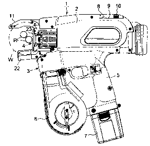
Fig. 1 is a side view showing a reinforcing bar binding
machine.
Fig. 2 is a plan view showing a power switch portion of
the reinforcing bar binding machine.
Fig. 3(a) is a front view showing a binding wire feed
mechanism.
Fig. 3(b) is a side view showing the binding wire feed
mechanism.
Fig. 4 is a side view showing the binding wire feedmechanism
in a state in which a binding wire is cut off.
Fig. 5 is a flow chart at the time of turning on an electric
power source of the reinforcing bar binding machine.
- 4 -
CA 02594731 2007-07-12
In this connection, each reference numeral in the drawing
shows each component as follows. Reference numeral 1 is a
reinforcing barbinding machine,reference numeral 2 is ahousing,
reference numeral 3 is a binding wire feed mechanism, reference
numeral 4 is a binding wire twist mechanism, reference numeral
5 is a grip portion, reference numeral 6 is a magazine, reference
numeral 7 is a battery pack, reference numeral 8 is an electric
power switch, reference numeral 9 is a voltage warning LED,
reference numeral 10 is a twist torque setting dial, reference
numeral 11 is a binding wire guide nose, reference numeral
12 is a trigger lever, reference numeral 19 is a rotary cutter,
reference numeral 20 is a pin, reference numeral 21 is a cutter
lever, reference mark R is a reinforcing bar and reference
mark W is a binding wire.
Best Mode for Carrying Out the Invention:
Referring to the drawings, an embodiment of the present
invention will be explained below.
Fig. 1 is a view showing an electric type reinforcing
bar binding machine 1. A binding wire feed mechanism 3 and
a binding wire twist mechanism 4 are incorporated into a housing
2. In a magazine 6 arranged in the front of a grip portion
5 of the housing 2, a binding =wire reel (not shown) is charged.
To an end portion of the grip portion 5, a battery pack 7,
into which NiMH battery is incorporated, is attached. Through
an electric power circuit board (not shown) , the battery pack
- 5 -
CA 02594731 2007-07-12
7 supplies electric power to a feed motor of the binding wire
feed mechanism 3 and a feed motor of the binding wire twist
mechanism 4.
As shown in Figs. 1 and 2, there are provided an electric
power source switch 8, a warning detection LED 9 and a twist
torque adjustment dial 10 on an upper face at the rear of the
reinforcing bar binding machine 1. In the housing 2, a buzzer
(not shown) for warning related to voltage is provided. In
the periphery of the twist torque adjustment dial 10, graduations
from 1 to 8 are indicated. When an indicator of the twist
torque adjustment dial 10 is adjusted at the graduation of
8, the twist torque can be set at the maximum value.
When the battery pack 7 is attached to the reinforcing
bar binding machine 1 and then the electric power switch 10
is turned on, an initializing action of the reinforcing bar
binding machine 1 is carried out. In the initializing action,
the binding wire feed mechanism 3 feeds a predetermined length
of the binding wire toward the binding wire guide nose 11 arranged
on the upside. Then, a forward end portion of the binding
wire is cut off with a rotary cutter of a binding wire cutting
mechanism described later, so that the forward end portion
of the binding wire can be positioned. The binding wire twist
mechanism 4 conducts a series of actions including a clamping
action and a twisting action under the condition that the binding
wire twist mechanism 4 does not hold the binding wire. After
that, the binding wire twist mechanism 4 is stopped at an initial
- 6 -
CA 02594731 2007-07-12
position and put into a standby state. After the binding wire
twist mechanism 4 has been put into the standby state, when
the trigger lever 12 is pulled, one cycle of the reinforcing
bar binding action, which includes a feeding action of the
binding wire, a clamping action, a drawing action, a cutting
action and a twisting action, is continuously carried out.
A control portion watches voltage of the battery pack
7 through a voltage detection circuit during a binding action.
When voltage of the battery pack 7 drops to a predetermined
voltage at which it is recommended to charge the battery pack
7, the buzzer is made to ring and warning detection LED 9 is
turned on so that a reduction of voltage is informed. When
an indicator of the twist torque adjustment dial 10 is adjusted
at the graduation 8 and the electric power source switch is
turned on under the condition that the trigger lever is pulled,
the control portion is put into the warming-up mode described
later and a binding wire cutting action is repeatedly carried
out by a predetermined times.
As shown in Fig.3(a), the binding wire feed mechanism
3 includes: a driving gear 14 having a V-groove that is driven
by a feed motor 13; and a driven gear 15 having a V-groove
which is meshed with the driving gear 14 having the V-groove.
A binding wire is sent out being interposed between the driving
gear 14 having the V-groove and the driven gear 15 having the
V-groove. Binding wire W is sent upward from a binding wire
reel arranged in the magazine. Binding wire W, which has been
- 7 -
CA 02594731 2007-07-12
sent out from the binding wire reel, is formed into an arcuate
shape along a guide groove on an inner circumference of the
binding wire guide nose 11 shown in Fig. 1 and goes round
reinforcing bars R, and a tip portion of binding wire W threads
between the clamps of the binding wire twist mechanism 4.
The driven gear 15 having the V-groove is attached to
a lever 16 and elastically contacted with the driving gear
14 having the V-groove by a spring force generatedby a compressive
coil spring 17 attached to the lever 16. When a lower end
portion of the lever 16 is pushed to the central side, that
is, to the left in Fig. 3(a), the driven gear 15 having the
V-groove, which is attached to an upper portion of the lever
16, is separated from the driving gear 14 having the V-groove
arranged on the motor 13 side. Therefore, binding wire W can
be threaded between the driving gear 14 having the V-groove
and the driven gear 15 having the V-groove. In a lower portion
between the two gears 14 and 15, a funnel-shaped binding wire
guide 18 is provided. Binding wire W is threaded into the
binding wire guide 18 from below and set between the driving
gear 14 having the V-shaped groove and the driven gear 15 having
the V-groove.
In an upper portion of the binding wire feed mechanism
3, a rotary cutter 19 for cutting the binding wire is arranged.
The rotary cutter 19 includes: a columnar pin 20 in which
a groove is formed in the radial direction; and a cutter lever
21 engaged with the pin 20. In a pin engaging portion of the
- 8 -
CA 02594731 2007-07-12
cutter lever 21, a cutter portion 21a corresponding to the
groove of the pin 20 is formed. When the binding wire is threaded
into the groove of the pin 20 and then the cutter lever 21
is rotated, a cutter portion 21a of the cutter lever 21 shears
binding wire W at a position on the outer circumference of
the pin 20.
Although not shown in the drawing, an end portion of the
cutter lever 21 is connected to a slider of the binding wire
twist mechanism 4 through a link and moved being linked with
the binding wire twist mechanism 4. Therefore, the end portion
of the cutter lever 21 rotates in the arrowed direction from
the initial position shown in Fig. 3(b) so that the binding
wire can be cut. As shown in Fig. 4, after the end portion
of the cutter lever 21 has cut off the binding wire, it is
returned to the initial position being linked with the binding
wire twist mechanism.
The binding wire twist mechanism 4 includes: a twist shaft
not shown in Fig.1; and three clamping plates attached to a
forward end portion of the twist shaft. The three clamping
plates are arranged inside the side cover 23 which is located
between the binding wire guide nose 11 and the lower side guard
22. Two clamping plates, which are arranged on both sides
of the fixed central clamping plate, are opened and closed
by a cam mechanism.
The binding wire is sent out from between the central
clamping plate and one of the outside clamping plates. The
- 9 -
CA 02594731 2007-07-12
control unit (not shown) stops feeding the binding wire after
the binding wire corresponding to the predetermined number
of turns has been sent out. At this time, a tip portion of
the binding wire reaches a predetermined position in the binding
wire guide nose 11. The clamping plate of the binding wire
twist mechanism 4 clamps a binding wire loop and pulls back
the binding wire. At the same time, the binding wire twist
mechanism 4 slides and cuts off a rear end of the binding wire
loop. Therefore, the binding wire loop is cut away from the
successive binding wire. Next, when the twist shaft of the
binding wire twist mechanism 4 and the clamping plate are driven
being rotated and a clamp portion of the binding wire loop
is twisted, the reinforcing bars are bound. When an intensity
of twist torque of the twist motor is raised to a predetermined
setting value, twisting operation is stopped. After that,
the twist motor is reversed and the clamping plate is opened
and the twist shaft is returned to the initial position. In
this way, one cycle of the binding step is completed.
Next, a warming-up function will be explained below.
In the case where the outside air temperature is low, the viscosity
of grease coated on the binding wire twist mechanism 4 is raised,
which causes problems in the operation of the binding wire
twist mechanism 4. In order to solve the above problems caused
in the environment of low temperature, the reinforcing bar
binding machine 1 includes a warming-up function. In this
case, the control system is composed as follows. When the
- 10 -
CA 02594731 2007-07-12
electric power source is turned on while the twist torque
adjustment dial 10 and the trigger lever 12 (the trigger switch)
are being respectively maintained in a specific state, the
warming-up mode is attained.
Fig. 5 is a flow chart showing operation at the time of
starting. When the electric power source switch 8 is turned
on (step 101) , the control unit reads in states of the trigger
lever 12 and the twist torque dial 10 (steps 102 and 103).
In the case where the trigger lever 12 is turned off or the
twist torque adjustment dial 10 is set at a graduation except
for the graduation 8, a usual initialization action is carried
out which includes a binding wire feed action, a binding wire
twist mechanism drive action, a binding wire cutting action
and an initialization position returning action (step 104).
After the above actions have been carried out, the binding
machine is put into a state of standby (step 107).
On the other hand, in the case where the electric power
source switch is turned on while the twist torque adjustment
dial 10 is being set at the graduation 8 and the trigger lever
12 is being pul led, the binding machine is put into the warming-up
mode. Therefore, a reciprocating action of the binding wire
twist mechanism 4 is carried out, that is, a binding wire cutting
action is carried out (step 105). This action is repeated
until the number of the cutting actions reaches 50 times (step
106) . After the binding wire cutting action has been carried
out by 50 times, the binding machine is put into the state
- 11 -
CA 02594731 2009-08-10
of standby (step 107) . Due to the above operation, a temperature
of grease is raised and viscosity is lowered. Further, a
temperature of NiMH battery is also raised and NiMH battery
is activated. Therefore, even when the outside temperature
is low, it is possible to conduct a normal binding action.
In this warming-up mode, the binding wire is not fed but
the binding wire is only cut off. Therefore, the cutting wire
is not wasted. In the case where the warming-up operation
is stopped for some reasons, only when the electric power source
switch 8 is turned off, the electric power source can be shut
off and all actions of the binding machine are stopped. In
the above embodiment, the motor drive adjustment dial is used
as a torque adjustment dial. However, the torque adjustment
dial is not limited to the motor drive adjustment dial. An
adjustment dial for adjusting a motor rotation or motor speed
may be used as the torque adjustment dial.
In this connection, it should be noted that variations
may be made within a scope of the present invention. It is
apparent that the present invention can be applied to a power
tool except for the reinforcing bar binding machine. In addition,
it is apparent that these variations or changes can also be
included in the scope of the invention.
The present application is based on Japanese Patent
Application No. 2005-006818 filed on January 13, 2005.
- 12 -
CA 02594731 2007-07-12
Industrial Applicability:
According to one or more embodiments of the present
invention, it is possible to prevent the occurrence of failure
in operation when a reinforcing bar binding machine is used
in an environment of low temperature.
- 13 -