Note: Descriptions are shown in the official language in which they were submitted.
CA 02595222 2007-07-18
WO 2006/081009 PCT/US2005/045937
TITLE OF THE INVENTION
Method and Device to Improve Operation of a Fuel Cell
FIELD OF THE INVENTION
An invention and method of conditioning a fuel cell or cells to improve
operation of said cell or cells.
BACKGROUND OF THE INVENTION
Fuel cells are devices that convert fluid streams containing a fuel, for
example hydrogen, and an oxidizing species, for example, oxygen or air, to
electricity, heat and reaction products. Such devices comprise an anode,
where the fuel is provided; a cathode, where the oxidizing species is
provided;
and an electrolyte separating the two. The fuel and/or oxidant can be a liquid
or
gaseous material. The electrolyte provides an ionic pathway for the ions to
move between the anode, where the ions are produced by reaction of the fuel,
to the cathode, where they are used to produce the product. The electrons
produced during formation of the ions are used in an external circuit, thus
producing electricity.
A Polymer Electrolyte Membrane (PEM) fuel cell is a type of fuel cell
where the electrolyte is a polymer electrolyte. Other types of fuel cells
include
Solid Oxide Fuel Cells (SOFC), Molten Carbonate Fuel Cells (MCFC),
Phosphoric Acid Fuel Cells (PAFC), etc. As with any electrochemical device
that operates using fluid reactants, unique challenges exist for achieving
both
high performance and long operating times. In order to achieve high
performance it is necessary to reduce the electrical and ionic resistance of
components within the device. Recent advances in the polymer electrolyte
membrane have enabled significant improvements in the power density of PEM
fuel cells. As is well known in the art, decreasing the thickness of the
polymer
electrolyte membrane can reduce the membrane ionic resistance, thus
increasing fuel cell power density. Within this application power density is
.defined as the product of the voltage and current in the external circuit
divided
by the geometric area of the active area in the cathode. The active area is
the
area in which the catalyst exposed to the fuel and oxidant.
However, reducing the membranes physical dimensions can increase
the susceptibility to damage from other device components leading to shorter
cell lifetimes. Various improvements have been developed to mitigate this
problem. For example, in US Patent No. RE 37,307 to Bahar et al. the polymer
1
CA 02595222 2007-07-18
WO 2006/081009 PCT/US2005/045937
electrolyte membrane is reinforced with a porous reinforcement to increase its
strength. Although this approach is successful in improving cell performance
and increasing lifetimes, higher power density would be even more desirable.
Although there have been many improvements to fuel cells in an effort
to improve power density, most have focused on using materials that improve
performance. Very few have focused on specific operational methods or
devices that would act with a given set of materials to maximize power density
given those materials. It is well known in the art that after assembling
either a
single cell, i.e., a cell with only a single anode and cathode, or a fuel cell
stack,
1o i.e, a number of single cells connected together, typically in series, that
there is
a period of "break-in" required when the cell or stack performance improves
with operation. Ideally, one would like to have the highest possible power
output immediately after assembly as shown in Figure 1, in the curve labeled
"Desired". In practice, though, the power output initially is lower, and
improves
with time for a period of time as shown in Figure 1, in the curve labeled
"Typical". Generally, a practitioner will therefore "break-in" the cell for a
period
of time monitoring the power density, or as is more easily achieved in
practice,
the current density at a given fixed voltage, until it stops increasing. At
this
point, the cell is "broken-in" and ready to operate under normal use
conditions.
Ideally, not only would one like to have the highest possible power density
after
the break-in procedure, but one would also like to have the time to reach this
point to be as short as possible. The shorter this "break-in" time, the sooner
the
cell or stack can operate for its intended purpose.
There is no standard measurement established in the prior art to
determine the effectiveness of break-in or conditioning procedures. In this
application, we will the use the following: the output current density at 0.6
volts
of a fuel cell is monitored and recorded as a function of time during the
application of a given break-in procedure. After 18 hours, the power density
at
0.6 volts is calculated from a polarization curve. This power density can then
be used as a means of comparison between cells that have been conditioned
with various procedures. The higher the value, the better the conditioning
procedure. To measure the break-in time, two values are calculated from the
recorded current density at 0.6 volts versus time. The first is the time
required
to reach 75% of the current density achieved at 18 hours. The second is the
time required to reach 90% of the current density achieved at 18 hours. Better
break-in or conditioning procedures will give shorter times. An illustration
of
these measurements is shown in Figure 2, and complete details of the
measurement protocols are given below.
2
CA 02595222 2007-07-18
WO 2006/081009 PCT/US2005/045937
The specific conditioning or break-in procedures used among
practitioners in the art varies, ranging from performing a number of
polarization
curves on the newly assembled cell or stack, to applying an external load to
the
cell and holding the voltage or current constant for a fixed period of time.
Also
known in the art are conditioning regimes where the voltage or current is
varied
during break-in, the cell is short circuited once or many times, and an
elevated
temperature and/or pressure is/are applied to the cell.
After break-in is completed and the fuel cell or stack is operating under
normal conditions, the power density typically decreases as the cell or stack
continues to operate. This decrease, described by various practitioners as
voltage decay, fuel cell durability, or fuel cell stability, is not desirable
because
less useful work is obtained as the cell ages during use. Ultimately, the cell
or
stack will eventually produce so little power that it is no longer useful at
all.
Therefore, it would be highly desirable if during operation, a procedure to
recover the "lost" power could be used. Although it has been recognized that
after removing the external load from a cell or stack that some recovery
occurs
naturally, approaches specifically designed to recover performance would be
very valuable.
SUMMARY OF THE INVENTION
The instant invention is'a method of conditioning a fuel cell having an
anode supplied with a fuel, and a cathode supplied with an oxidant comprising
the steps of: (i) applying a first external load to said fuel cell to produce
a first
voltage which is less than open circuit voltage for a first period of time
less than
about 20 minutes; (ii) Removing the external load for a second period of time
less than about 2 minutes; and (iii) Applying a second external load to said
fuel
cell to produce a second voltage which is less than open circuit voltage for a
.third period of time less than about 20 minutes. Inventors have discovered
the
surprising result that the use of such a conditioning regime improves power
density at 0.6 volts, and decreases break-in time. Furthermore, and equally
surprising, when the inventive conditioning procedure is used to improve power
density during fuel cell operation, the power density observed after using the
inventive conditioning process is significantly higher than the value before
the
conditioning, and may give power densities close to those observed after
initial
break-in.
In further embodiments of the present invention the method described
above may be applied to a polymer electrolyte membrane fuel cell. In this
embodiment, said first period, said second period and said third period of
time
3
CA 02595222 2007-07-18
WO 2006/081009 PCT/US2005/045937
may each be greater than about 5 seconds. Additionally, the first and second
external loads may be selected so that said first voltage is different than
said
second voltage, preferably chosen so that said first voltage is between about
0.4 and about open circuit voltage, most preferably about 0.6 volts; and said
second voltage is between about 0.0 volts and 0.6 volts, most preferably about
0.3 volts. Process steps i through iii may be repeated at least twice, or at
least
thrice. Further, the methods may be performed when said fuel comprises
hydrogen, or methanol. Additionally, any of the inventive methods above may
optionally comprise the additional step of removing said second external load
1o for a fourth period of time less than about 2 minutes, or for a period of
about 1
minute, or for a period between about 5 seconds and about 120 seconds.
The methods of the instant invention may be applied during the first
about 24 hours of operation of said fuel cell, or alternatively after about 24
hours of operation.
In another embodiment of the instant invention, said external load and
said second external load are selected so said first voltage is about 0.6
volts,
said second voltage is about 0.3 volts. Further, said first period of time may
be
selected to be about 15 minutes, said second period of time about 1 minute,
and said third period of time about 15 minutes. Alternatively, and preferably,
said first period of time is between about 5 seconds and about 120 seconds,
said second period of time is between about 5 seconds and about 120 seconds,
and said third period of time is between about 5 seconds and about 120
seconds. Alternatively, any of the inventive methods above may optionally
comprise the additional step of removing said second external load for a
fourth
period of time less than about 2 minutes, or for a period of about 1 minute,
or
for a period between about 5 seconds and 120 seconds.
Another embodiment of the invention is a method of conditioning a
polymer electrolyte membrane fuel cell having an anode, a cathode, and an
electrolyte comprising a polymer having an anode supplied with a fuel, and a
cathode supplied with an oxidant comprising the steps of. (i) applying a first
external load to said fuel cell to produce a first voltage which is less than
open
circuit voltage for a first period of time less than about 20 minutes; (ii)
Removing
the external load for a second period of time less than about 2 minutes; and
(iii)
Applying a second external load to said fuel cell to produce a second voltage
which is less than open circuit voltage for a third period of time less than
about
20 minutes; whereby liquid water is applied to the fuel cell during any of
steps
(i), (ii) or (iii).
4
CA 02595222 2007-07-18
WO 2006/081009 PCT/US2005/045937
Another embodiment of the invention is a method of conditioning a
polymer electrolyte membrane fuel cell having an anode, a cathode, and an
electrolyte comprising a polymer having an anode supplied with a fuel, and a
cathode supplied with an oxidant comprising the steps of. (i) applying a first
external load to said fuel cell to produce a first voltage which is less than
open
circuit voltage for a first period of time less than about 20 minutes; (ii)
Removing
the external load for a second period of time less than about 2 minutes; and
(iii)
Applying a second external load to said fuel cell to produce a second voltage
which is less than open circuit voltage for a third period of time less than
about
io 20 minutes; and (iv) applying a fuel pressure of greater than about one
psig to
the anode, and an oxidant pressure similar to said fuel pressure to the
cathode.
Said application of a fuel and oxidant pressure may occur during steps (i),
(ii) or
(iii) or as a separate step.
Another embodiment of the invention is a method of conditioning a
polymer electrolyte membrane fuel cell having an anode, a cathode, and an
electrolyte comprising a polymer having an anode supplied with a fuel, and a
cathode supplied with an oxidant comprising the steps of. (i) applying a first
external load to said fuel cell to produce a first voltage which is less than
open
circuit voltage for a first period of time less than about 20 minutes; (ii)
Removing
the external load for a second period of time less than about 20 minutes; and
(iii) Applying a second external load to said fuel cell to produce a second
voltage which is less than open circuit voltage for a third period of time
less.
than about 20 minutes; whereby said polymer electrolyte membrane fuel cell is
held at a temperature of between about 60 C and about 90 C during any of
steps (i) through (iii).
In yet another embodiment of the invention, a method of conditioning a
fuel cell comprises the steps of. (i) assembling a fuel cell comprising an
anode,
a cathode, an electrolyte and means of supplying gas to the cathode and
anode; (ii) applying liquid water using an inert gas carrier to said anode and
said cathode of said fuel cell at a temperature between about 60 C and about
90 C; and (iii) holding said cell at said temperature for a period greater
than
about 1 hour.
Another embodiment of the invention is a polymer electrolyte membrane
electrode assembly conditioned by a method comprising the steps of. (i)
applying a first external load to said fuel cell to produce a first voltage
which is
less than open circuit voltage for a first period of time less than about 20
minutes; (ii) removing the external load for a second period of time less than
about 2 minutes; and (iii) applying a second external load to said fuel cell
to
5
CA 02595222 2007-07-18
WO 2006/081009 PCT/US2005/045937
produce a second voltage which is less than open circuit voltage for a third
period of time less than about 20 minutes. In alternative embodiments, a
membrane electrode assembly can be conditioned with this method wherein
said first external load and said first and said second external load are
selected
so said first voltage is about 0.6 volts and said second voltage is about 0.3
volts. In a further embodiment of this method, said first period of time is
about
minutes, said second period of time is about 1 minute and said third period
of time is about 15 minutes. Alternatively and preferably, said first period
of
time is between about 5 seconds and about 120 seconds, said second period of
1o time is between about 5 seconds and about 120 seconds, and said third
period
of time is between about 5 seconds and about 120 seconds. Further
embodiments of the invention are membrane electrode assemblies prepared as
described herein where said membrane electrode assembly comprises a
polymer containing ionic acid functional groups attached to a polymer
15 backbone, and optionally expanded polytetrafluoroethylene. In yet more
embodiments of the invention, said ionic acid functional groups of said
membrane electrode assembly are selected from the group of sulfonic,
sulfonimide and phosphonic acids. In yet more embodiments, said membrane
electrode assembly may be conditioned by any of the inventive methods above
whereby said methods above may optionally comprise the additional step of
removing said second external load for a fourth period of time less than about
2
minutes, or for a period of about 1 minute, or for a period between about 5
seconds and 120 seconds.
Another embodiment of the invention is a membrane electrode
assembly conditioned by a method comprising the steps of: (i) Assembling a
fuel cell comprising an anode, a cathode, an electrolyte and means of
supplying
gas to the cathode and anode; and (ii) Applying liquid water using an inert
gas
carrier to said anode and said cathode of said fuel cell at a temperature
between about 60 C and about 90 C; and (iii) Holding said cell at said
temperature for a period greater than about 1 hour. A further embodiment of
the invention is a membrane electrode assembly prepared as described herein
where the membrane electrode assembly comprises a polymer containing ionic
acid functional groups attached to a polymer backbone, and optionally
expanded polytetrafluoroethylene. In yet one more embodiment of the
invention, said ionic acid functional groups of said membrane electrode
assembly are selected from the group of sulfonic, sulfonimide and phosphonic
acids.
6
CA 02595222 2007-07-18
WO 2006/081009 PCT/US2005/045937
Yet further embodiments of the invention include methods of operating a
fuel cell wherein said methods comprises the steps of (i) assembling a fuel
cell
comprising an anode, a cathode and a polymer electrolyte interposed
therebetween, and (ii) applying a break-in procedure, wherein said break-in
procedure gives a 90% break-in time of less than about 4 hours. Additionally,
said 90% break-in time may be less than about 2 hours, or less than about 1
hour. Additional embodiments include methods of operating a fuel cell wherein
said methods comprise the steps of (i) assembling a fuel cell comprising an
anode, a cathode and a polymer electrolyte interposed therebetween, and (ii)
1o applying a break-in procedure, wherein said break-in procedure gives a 75%
break-in time of less than about 2 hours. Additionally, said 75% break-in time
may be less than about 1 hour, or less than about 0.5 hours.
One further embodiment of the present invention is an apparatus
comprising: (i) Means for applying a first external load to said fuel cell to
produce a first voltage which is less than open circuit voltage for a first
period of
time less than about 20 minutes; (ii) Means for removing the external load for
a
second period of time less than about 2 minutes; (iii) Means for applying a
second external load to said fuel cell to produce a second voltage which is
less
than open circuit voltage for a third period of time less than about 20
minutes.
The present invention is a distinct improvement over conditioning
procedures previously known both because of the higher power density
obtained and because of the shorter time required to reach the higher power
density. Such improvements will improve fuel cell manufacturing times by
decreasing the time required for quality control testing. Additional
application
areas for fuel cells will be possible because of the higher power density.
Finally, when used during fuel cell operation as a recovery procedure, the
improved recovery will allow the fuel cells to operate longer in actual
operation,
thereby greatly and broadly increasing their utility.
DESCRIPTION OF THE DRAWINGS
The operation of the present invention should become apparent from
the following description when considered in conjunction with the
accompanying drawings, in which:
Figure 1 is a schematic of the voltage produced by a fuel cell versus
time during break-in showing typical results and the ideal or desired
behavior.
Figure 2 compares the observed current density with time for break-in
following the instant invention, and a break-in procedure according to prior
art.
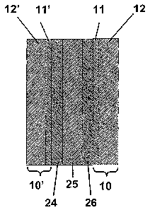
Figure 3 is a schematic of a membrane electrode assembly.
7
CA 02595222 2010-11-08
WO 2006/081009 PCT/US2005/045937
DETAILED DESCRIPTION OF THE INVENTION
The instant invention is both a means of conditioning a fuel cell and a
fuel cell conditioned by such means. The fuel cell can be of any type, for
example molten carbonate, phosphoric acid, solid oxide or most preferably, a
polymer electrolyte membrane (PEM) fuel cell. Such PEM fuel cells comprise
an anode, a cathode and a polymer electrolyte sandwiched between them. The
polymer used as a polymer electrolyte comprises a polymer containing ionic
acid functional groups attached to the polymer backbone, wherein said ionic
acid functional groups are selected from the group of sulfonic, sulfonimide
and
phosphonic acids; and optionally further comprises a fluoropolymer. Said
polymer may be selected from the group containing perfluorosulfonic acid
polymers, polystyrene sulfonic acid polymers; sulfonated Poly(aryl ether
ketones); and polymers comprising phthalazinone and a phenol group, and at
least one sulfonated aromatic compound. The polymer may also comprise
expanded polytetrafluoroethylene. Said expanded polytetrafluoroethylene may
be a membrane having a porous microstructure of polymeric fibrils and
optionally nodes; an ion exchange material impregnated throughout the
membrane, wherein the ion exchange material substantially impregnates the
membrane to render an interior volume of the membrane substantially
occlusive. A particularly preferable polymer membrane is one prepared
according to Bahar, et. al. as described in RE 37,307.
The anode and cathode electrodes comprise appropriate catalysts that
promote the reduction of fuel (e.g., hydrogen) and the oxidation of the
oxidant
(e.g., oxygen or air), respectively. For example, for PEM fuel cells, anode
catalysts may include, but are not limited to, pure noble metals, for example
Pt,
Pd or Au; as well as binary, ternary or more complex alloys of said pure noble
metals. Pure Pt is particularly preferred for the anode when using pure
hydrogen as the fuel. Pt-Ru alloys are particularly preferred catalysts when
using reformed gases as the fuel. Pure Pt is a preferred catalyst for the
cathode in PEM fuel cells. Non-noble metal alloys catalysts are also used,
particularly in non-PEM fuel cells, and as the temperature of operation
increases. The anode and cathode may also, optionally, include additional
components that enhance the fuel cell operation. These include, but are not
limited to, an electronic conductor, for example carbon, and an ionic
conductor,
for example a perfluorosulfonic acid based polymer. Additionally, the
8
CA 02595222 2007-07-18
WO 2006/081009 PCT/US2005/045937
electrodes are typically porous as well, to allow gas access to the catalyst
present in the structure.
PEM fuel cells, shown schematically in Fig. 3, as used herein may
include a membrane electrode assembly (MEA) comprising an anode 24, a
cathode 26 and an electrolyte 25, and optionally, gas diffusion layers 10 and
10' (GDM), preferably comprising carbon, and optionally, a bipolar plate for
distributing the gas across the active area (not shown in Fig. 3). The GDM may
also optionally be comprised of a macrolayer 12 and 12', and a microlayer 11
and 11'. Additionally, such PEM fuel cells may also optionally comprise stacks
comprising a series of MEAs, GDMs and bipolar plates, or any combination
thereof. The inventive conditioning procedures described below may be
applied to these PEM fuel cells to produce an MEA or fuel cell that has been
conditioned before its final use in a power producing fuel cell module.
The temperature of operation of the fuel cell varies depending on the
type of cell, the components used, and the type of fuel. For example, PEM fuel
cells typically operate at temperatures between about room temperature and
about 150 C.
Inventors have discovered, surprisingly, that by using a specific
conditioning procedure detailed below on a fuel cell that power density can be
increased, and break-in time reduced. The method applies to the conditioning
of a fuel cell having an anode supplied with a fuel, and a cathode supplied
with
an oxidant. It comprises the steps of: (i) Applying a first external load to
said
fuel cell to produce a first voltage which is less than open circuit voltage
for a
first period of time less than about 20 minutes; (ii) Removing the external
load
for a second period of time less than about 2 minutes; and (iii) Applying a
second external load to said fuel cell to produce a second voltage which is
less
than open circuit voltage for a third period of time less than about 20
minutes.
As used herein the open circuit voltage is defined as the potential measured
between the anode and cathode when fuel is applied to the anode and oxidant
is applied to the cathode, but there is no external load applied to the cell
other
than a high impedance device capable of measuring potential. The open circuit
voltage is thus measured using a high impedance voltmeter or other high
impedance device such as a potentiostat or various fuel cell test stations
known
in the art. The inventive conditioning procedure can be used initially after
assembling the cell, for example during the first about 24 hours of operation
of
the fuel cell, wherein it is called herein a "break-in" procedure. The
conditioning
9
CA 02595222 2007-07-18
WO 2006/081009 PCT/US2005/045937
procedure can also be used after the fuel cell has been operating for a period
of
time, for example at any time greater than about 24 hours up until the cell is
permanently shutdown or otherwise fails. The steps (i) through (iii) may be
repeated once, twice, thrice or preferably, many times over an extended period
of time, for example for many hours. In order to minimize the total cycle
time, it
may be preferable to minimize said first, second and third periods of time.
One
preferable cycle is having said first voltage equal to 0.6 volts, said second
voltage equal to 0.3 volts, and said first, second and third periods of time
all
equal to 30 seconds.
In another embodiment of the instant invention, an electronic,
pneumatic, mechanical, or electromechanical device capable of producing
steps (i) through (iii) above may be constructed. Said device automatically
performs said steps, thereby increasing power density and decreasing break-in
time.
The above conditioning procedure comprising steps (i) through (iii) may
also be combined with other conditioning steps known in the art. These
include, but are not limited to using elevated temperatures; elevated
pressures;
performing a so-called hydrogen pump, where hydrogen is applied to the anode
and cathode then the cell operated so hydrogen is generated alternatively at
the anode and cathode; or any combination of the above.
Additionally, inventors have discovered that a method comprising the
application of liquid water to a PEM fuel cell at elevated temperature
surprisingly also increases power density and decreases break-in time. In this
embodiment, a PEM fuel cell or MEA is held at an elevated temperature in the
presence of liquid water for a period of time. Said period of time can vary
between a 1-2 minutes and preferably, many hours, and most preferably
greater than about 6 hours. Said liquid water can be applied using any of
numerous methods known in the art. For example, the MEA may be soaked in
elevated temperature water. Alternatively, one may saturate a non-reacting gas
3o by passing it through a water bottle held at a temperature above the
temperature of the PEM fuel cell. The non-reacting gas can be an inert gas
such as He or Ar , or preferably, a less expensive non-reacting gas, such as
nitrogen. The said elevated temperature in this process is chosen to be higher
than the expected operating temperature of the MEA or PEM fuel cell,
preferably by 10 to 30 C. For example, if the operating temperature of the
cell
is expected to be 70 C, the break-in elevated temperature soak in the presence
CA 02595222 2007-07-18
WO 2006/081009 PCT/US2005/045937
of liquid water will be performed at 80 - 100 C, and preferably at 90 C. In
this
latter case, using the method described above, the water bottle temperature
must be above 90 C, for example at 95 C. As is well known in the art, care
must be taken when using this procedure to prevent condensation in all the
incoming lines to the cell by heating said lines to at, or slightly above the
bottle
temperature. This embodiment may also be combined with one or more
additional break-in steps, including but not limited to any of those described
above.
EXAMPLES
The following procedures and methods were used in the examples that
follow.
Cell Hardware and Assembly
For all examples, a standard 25 cm2 Active Area (AA) hardware (Fuel
Cell Technologies, Inc.) was used for membrane electrode assembly (MEA)
performance evaluation. This hardware is henceforth referred to as "standard
hardware" in the rest of this application. The standard hardware consisted of
graphite blocks with triple channel serpentine flow fields on both the anode
and
cathode sides. The path length is approximately 560 mm and the groove
dimensions are 0.69 mm width and 0.84 mm depth respectively. Every cell was
assembled with a 0.175 - 0.275 mm silicone gasket with a square window of
5.0 cm X 5.0 cm, and a 0.025 mm polyethylene napthalate (PEN) film (available
from Tekra Corp., Charlotte, NC.) PEN gasket, referred to as the `sub-gasket',
with an open window of 4.8 X 4.8 cm on both the anode and cathode sides.
The thickness of the silicone gasket was chosen for each cell to maintain
approximately the same compression in each cell after assembly. Each cell
was assembled with CARBELTM CL gas diffusion medium (GDM, available
from W. L. Gore & Associates, inc., Newark, DE) with a nominal thickness of
0.41 mm on both the anode and cathode sides. This type of GDM is henceforth
referred to as "standard GDM" in the rest of this application. Three types of
MEAs were used to study the effects of break-in protocol on MEA performance:
PRIMEA MEA Series 5510, 5561 and 5621, all from W.L. Gore & Associates,
Inc. The MEA is assembled dry in all cases in the fuel cell. The dry state in
this
context refers to equilibrium at room temperature at a relative humidity (RH)
of
20 to 30 %. Cell hardware was assembled with the gasket, sub-gasket, and
GDM layers on either side of the MEA. Eight bolts were used and the cell was
compressed by tightening the bolts until a final bolt torque of 45 in-lb/bolt
was
11
CA 02595222 2007-07-18
WO 2006/081009 PCT/US2005/045937
attained. In order to ensure consistency in cell assembly, the bolts were
lubricated with Krytox lube. The thickness of the gasket and sub-gasket were
chosen so that an average GDM compression of 35 % could be attained using
this GDM. This average compression was necessary to ensure a good
electrical contact between the different layers within the active area of the
MEA
while not significantly compromising the porosity within the diffusion layer.
This
assembly procedure is henceforth referred to as the 'standard' cell assembly.
The cell is heated using cartridge heaters and cooled with natural convection,
i.e., no external coolant or cooling manifold is provided in this design.
Fuel Cell Test Station Description
Two different fuel cell test systems were used to evaluate the
performance. We distinguish these systems as System A (Globe Tech Station)
and System B (Teledyne Medusa TM Station). System B is designed for much
more precise control of RH of both the fuel and the oxidant. System A on the
other hand has an older design with lower humidification efficiency.
Therefore,
target relative humidities need to be attained by raising the humidifier
temperatures 5 to 10 C above the desired dew point. Also, another critical
difference is that System A allows for liquid water to be entrained into the
gas
stream. The effect of liquid water will be treated separately and is shown to
be a
critical variable in some of the examples discussed below.
Cell Start-up and Description of Break-in Protocols
After cell assembly using the procedure outlined above and connecting
the cell to either of the two systems described above, the cell was started
under
different operating conditions. For all the protocols described below, the
cell
temperature was set at 70 C or 80 C. All experiments were conducted either at
ambient pressure or 15 psig equally applied to both the anode and cathode
chambers. The humidifiers were set at 80 C and 75 C on the anode and
cathode sides for System A. These set points assure a dew point close to 70 C.
This doesn't count for the liquid water being carried in the gas stream. Since
System B has a superior humidification design, the humidifiers were set to
obtain a dew point of 70 C on the anode and cathode sides. All cells were
started with fuel and oxidant after the humidifiers and cell temperatures
reached
their predetermined set-points as mentioned above. The fuel was laboratory
pure hydrogen. The oxidant in all cases was air. For all experiments the
hydrogen gas stoichiometry was set at 1.2 and the air stoichiometry was set at
2Ø As used herein, stoichiometry is defined as a ratio of the actual gas
flow
12
CA 02595222 2007-07-18
WO 2006/081009 PCT/US2005/045937
rate divided by the flow rate needed to provide enough gas to exactly maintain
complete reaction at any given current in the cell. For example, a hydrogen
gas
stoichiometry of 1.2 on the anode means that the flow of hydrogen is 1.2 times
that needed for complete reaction of all the hydrogen at the operating current
of
the cell. The different conditioning procedures are described in more detail
below.
Measurement Protocols
The power density at 0.6 volts is defined as the power density at 0.6
volts measured at 70 C, and 0 psig and 100% RH after break-in for 18 hours
using any of the said protocols shown in Table 1. It is calculated as follows:
a
polarization curve is recorded in the following sequence of steps:
a. The cell is held at 0.6 volts for 10 min and the current density is
measured every 6 seconds from the 9th minute.
b. The current density is fixed for 3 min in the following order: 1200,
1400, 1600, 1800, 1200 mA cm2 and cell voltage data is
collected every 6 seconds.
c. The cell is set at 1 volts for 15 seconds.
d. The current density is set at 1000 mA cm2 for 4 minutes and the
cell voltage is measured every 6 seconds from the 2nd minute.
e. The current density is fixed for 3 minutes in the following order:
800, 700, 500, 250, 100, and 1200 mA CM -2 and the cell voltage
data is collected every 6 seconds.
f. The cell is set at 0.6 volts for 3 min and the current density
values are recorded every 6 seconds during the 3rd minute.
The power density is then calculated by multiplying the average of the current
densities measured in step (f) and (a) by 0.6 to obtain a value in mW cm 2.
The break-in time is defined as the time to reach a current density of
either 75% or 90% of the current density at 0.6 volts measured at 18 hours. To
illustrate this calculation, an example of the recorded data is shown in
Figure 2
for Example 2 and Comparative Example 1. The current density measured at
0.6 volts after 18 hours for Example 1 was found to be 990 mA CM-2 . Ninety
and 75% of this value is 891 and 742 mA cm-2, respectively. From the current
density versus time trace in Figure 2, the time to reach 891 and 742 mA cm'2
was - 1.7 and - 0.64 hours, respectively. (The value for the 90% break-in time
shown in Table I for Example 2 is slightly higher than 1.7 hours because the
value in Table 1 is an average of multiple tests, only one of which is shown
in
Figure 2). Correspondingly, for Comparative Example 1, the current density at
13
CA 02595222 2007-07-18
WO 2006/081009 PCT/US2005/045937
0.6 volts after 18 hours was 845 mA cm-z. Ninety and 75% of this value is 760
and 634 mA cm 2, respectively. The time to reach these values is - 6.4 and
2.9 hours, respectively. Both of these times for Example I are shorter than
the
corresponding times for Comparative Example 1, so the break-in procedure of
Example 1 is more desirable.
In all Tables, the break-in conditions are illustrated (the cell temperature,
pressure, and voltage cycling mode). For the case with no cycling, the
comparative example, the cell potential was held constant at 0.6 volts for 18
hours. Two types of cycling were used in these examples, designated rapid,
1o and slow. The details of these two cycles are described in detail below,
but
each was repeated multiple times if required to reach the total time of break-
in
(or conditioning) application.
The cycling procedure designated as slow was performed as follows:
the cell was started with H2 and Air until a stable open circuit voltage (OCV)
was attained. After about 2 to 5 minutes the external load was changed to
bring
the cell to 0.6 volts where it was held for 15 min. Then, the external load
was
changed to bring the cell to 0.99 volts and held there for 1 minute. Then the
external load was changed again to bring the cell to 0.3 volts and held there
for
15 min. Then, the external load was removed, and the cell was allowed to
remain at open circuit voltage for one minute. This multi-step cycle was
repeated for 6 hours, after which a polarization curve was recorded. After
completion of the polarization curve the above cycle was continued for another
12 hours and finally a second polarization curve was recorded.
For the rapid cycling protocol, the cell was started with H2 and air flows
to the anode and cathode, respectively, until a stable open circuit voltage
(OCV) was attained. After about 2 to 5 minutes the external load was changed
to bring the cell voltage to 0.6 volts where it was held for 30 s. Then the
external load was removed to bring the cell to open circuit voltage, where it
was
held for 30 s. The external load was changed again to bring the cell to 0.3
volts, where it was held for 30 s. Then, the external load was removed, and
the
cell was allowed to remain at open circuit voltage for thirty seconds. This
multi-
step cycle was repeated continually for a total time of 6 hours, after which a
polarization curve was recorded. After completion of the polarization curve
the
same cycling procedure was repeated for another 12 hours and- a second
polarization curve was recorded. The total time that the cycling protocol was
applied to the cell was the same for both these "standard" slow and rapid
procedures, i.e., 18 hours. In some cases, as noted below in the examples,
14
CA 02595222 2007-07-18
WO 2006/081009 PCT/US2005/045937
the total time that the cycling protocol was applied was varied, with a time
shorter than 18 hours being used.
The power density was calculated based on the current density at 0.6
volts measured at 18 hours using the polarization curve procedure described
above. For the data described in the following Tables, the average power
density and one times the standard deviation (1 SD) are recorded based on at
least three replicates. Likewise, the average break-in time and 1 SD based on
the time to reach 75% or 90% of the current density are listed for the various
examples described below.
Description of Membrane Electrode Assembly (MEA):
Three types of PRIMEA Membrane Electrode Assemblies (MEAs)
obtained from W.L. Gore & Associates, Inc. were used: PRIMEA MEA Series
5510, PRIMEA MEA Series 5561 and PRIMEA MEA Series 5621. The
PRIMEA Series 5510 MEAs used a 25 pm GORE-SELECT membrane and
0.4 mg cm-2 Pt as catalyst on the anode and cathode. The Series 5561 MEAs
used a 25 m GORE-SELECT membrane, with 0.45 mg cm -2 Pt-Ru as anode
and 0.4 mg cm-2 Pt cathode. The Series 5621 MEAs used a 35 .tm GORE-
SELECT membrane, 0.45 mg cm-2 Pt-Ru as anode and 0.6 mg cm-2 Pt as
cathode.
Examples 1 - 8:
A series of tests were performed using PRIMEA Series 5621 with
standard GDM, standard cell hardware and System A test station. In all cases,
hydrogen gas was used as the fuel and the flow rate to the anode was set to a
stoichiometry of 1.2. The oxidant was air and the flow rate to the cathode was
set to a stoichiometry of 2Ø Further, the relative humidity of- both the
gases at
the inlet was set at 100%. The pressure applied to the anode and cathode, cell
temperature and type of cycling were varied in these examples as shown in
Table 1, as are the resulting power density at 0.6 volts and break-in times.
In
some cases, multiple tests were performed under the same conditions. In
those cases, an average of the resultant power density at 0.6 volts and break-
in
times is shown. In those cases where 3 or more tests were performed at a
given condition the standard deviation of the measured values was also
determined, and plus or minus one standard deviation is reported in the Table.
Fig. 2 shows the measured current density at 0.6 volts as a function of time
for
Example 2 and for Comparative Example 1 showing that the inventive method
CA 02595222 2007-07-18
WO 2006/081009 PCT/US2005/045937
of Example 2 has both a higher power density at 0.6 volts, and a shorter break-
in time.
Comparative Example I
Illustrative of prior art, the power density at 0.6 volts and break-in time
for 5621 MEAs was determined by using a break-in procedure where the cell
was held at 0.6 volts for 18 hours using standard GDM, standard cell hardware
and System A test station, relative humidity of the inlet gases set to 100%,
cell
temperature of 70 C, and stoichometries of the hydrogen fuel and air oxidant
of
1.2 and 2.0 respectively. Thus, this comparative example is the same in all
respects to Examples 1 and 2 except the test was done using a prior-art break-
in procedure. The power density for this case is 507 mW cm -2 and the break-in
time is 6.38 hours (90%) and 2.88 hours (75%). These values can be
compared in Table 1 to those obtained with inventive break-in procedures of
Example 1 and 2. Both the slow (Example 1) and rapid cycling (Example 2)
have higher power density at 0.6 volts and shorter break-in times than those
found for this Comparative Example. Fig. 2 further illustrates the advantage
of
the inventive method compared to this Comparative Example by showing
measured current density as a function of time for Example 2 compared to that
observed for this Comparative Example. The power density at 0.6V is higher,
and break-in time is shorter for the inventive method.
Table 1
Cell Pressure Voltage Power 90% 75% Break-in
Temperature (psig) cycling Density at 0.6 Break-in Time (h)*
( C) type volts Time (h)*
mW/cm2 *
Ex 1 70 0 Slow 610 11 2.88 0.53 1.32 0.31
Ex 2 70 0 Rapid 650 20 1.98 0.26 0.64 0.12
Ex3 70 15 Slow 618 4 1.10 0.12 0.40 0.14
Ex 4 70 15 Rapid 659 0.27 0.00
Ex 5 80 0 Slow 600 47 3.58 0.99 1.45 0.42
Ex 6 80 0 Rapid 591 1.10 0.27
Ex 7 80 15 Slow 630 0.88 0.38
Ex 8 80 15 Rapid 710 48 0.61 0.20 0.12 0.11
Comp 70 0 None 507 6.38 2.88
Ex I
* Where error values are shown, they are presented as one standard
deviation.
Examples 9 - 12:
Examples 9-12 shows the results with 5561 and 5510 MEAs using
conditions listed in Ex 2 and Ex 8 as shown in Table 1. The cell was built
with
standard hardware and gas diffusion medium. Again, System A type test station
16
CA 02595222 2007-07-18
WO 2006/081009 PCT/US2005/045937
was used to generate the experimental data. The inventive break-in procedures
thus are effective for all three types of MEAs used in Table 1 and 2.
Table 2
Electrode Cell Pressure Voltage Power 90% 75% Break-
Type Temp. (psig) cycling Density at Break-in in Time (h)
( C) type 0.6 volts Time (h)
mW/cmZ
Ex. 9 5561 70 0 Slow 684 6 1.43 0.60 0.70 0.14
Ex 10 5561 80 15 Raid 741 35 0.53 0.27 0.10 0.10
Ex 11 5510 70 0 Slow 662 9 1.88 0.10 0.72 0.26
Ex 12 5510 80 15 Rapid 738 24 1.50 0.44 0.48 0.26
Examples 13-14 and Comparative Example 2:
Examples 13 and Ex 14 show the data when reformate fuel with a 4%
air-bleed is used as the fuel instead of pure hydrogen. Comparative Example 2
is under identical conditions but with no type of voltage cycling. These
examples illustrate that the inventive break-in procedure is effective with
alternative fuels other than pure hydrogen.
Table 3
Electrode Cell Pressure Voltage Power 90% 75% Break-
Type Temp (psig) cycling Density at Break-in in Time (h)
( C) type 0.6 volts Time (h)
mW/cm2
Ex 13 5561 70 0 Slow 417 3.2 1.3
Ex 14 5561 70 0 Rapid 447 3.1 1.0
Comp 5561 70 0 None 396 7.9 3.8
Ex 2
Examples 15-18:
The effect of the presence of liquid water during the inventive break-in
procedures is shown in these examples. All cells were assembled with 5621
MEAs. The MEAs were conditioned using the conditions shown in Table 4.
Thus, the only difference between Examples 15 and 16, and between
Examplesl7 and 18 is the presence of liquid water introduced during the break-
in process. The presence of liquid water increases the power density at 0.6V
and decreases the break-in time when compared to the same procedure when
no liquid water is present.
17
CA 02595222 2007-07-18
WO 2006/081009 PCT/US2005/045937
Table 4
Cell Liquid Pressure Voltage Power 90% 75% Break-in
Temp. Water (psig) cycling Density at Break-in Time (h)
( C) type 0.6 volts Time (h)
(mW/cm2)
Ex 15 70 Yes 0 Rapid 601 2.2 0.7
Ex 16 70 No 0 Rapid 543 3.2 0.7
Ex 17 80 Yes 15 Rapid 696 0.58 0.21
Ex 18 80 No 15 Rapid 576 1.2 0.28
Examples 19 - 20:
Another variation of the instant invention was used in these examples.
The MEAs were first treated at 90 C with humidified N2 on both the anode and
cathode sides (also at a targeted dew point of 90 C) overnight, - 14 hours.
Then, the break-in procedure used in Example I was performed. The power
density at 0.6 volts was higher than that of Comparative Example 1, and the
break-in times were less than one-tenth that of Comparative Example 1.
Table 5
Cell Electrode Pressure Voltage Power 90% 75% Break-
Temp. Type (psig) cycling Density at Break-in in Time (h)
( C) type 0.6 volts Time (h)
m A/cm2
Ex 19 70 5621 0 Slow 601 0.75 < 0.25
Ex 20 70 5621 0 Slow 610 0.75 < 0.25
Examples 21
In this example, the use of the instant invention as a conditioning
procedure after initial break-in is demonstrated. A cell was assembled using a
5621 MEA as described previously. The break-in and testing conditions were
identical to Comparative Example 1, i.e. the break-in consisted of holding the
voltage at 0.6 volts for 18 hours. The power density at 0.6 volts after break-
in
was found to be 601 mW/cm2. The cell was then held at 0.6 volts for 7.6 hours
to simulate actual fuel cell operation. A polarization curve was then
recorded.
The power density was 629 mW/cm2. At this point, the inventive conditioning
procedure described in Example 8 was performed for 4 hours. A subsequent
polarization curve immediately following this procedure gave a power density
of
694 mW/cm2, an improvement of -10% from the power density before the
inventive conditioning was performed. Subsequently, the cell was again
operated at a constant 0.6 volts for an additional -88 hours and the power
density was observed to decrease, calculated to be 680 mW/cm2 after a
polarization curve was obtained. At this point, another inventive conditioning
procedure identical to the first was performed. The power density was
qualitatively observed to increase but it was not quantitatively measured
using
18
CA 02595222 2007-07-18
WO 2006/081009 PCT/US2005/045937
the standard procedure. The cell was then held for 16 h, under 15 psig at 80
C.
It was then held at 0 psig, 0.6 volts, 70 C for an additional -25 hours,
during
which time 3 different polarization curves were taken. The average power
density from these three polarization curves was 633 mW/cm2. Thus, after
-175 hours of power production, the power density had decreased from an
initial value of 694 mW/cm2 to 633 mW/cm2, indicating that the cell function
was
degrading with time. Finally, a conditioning identical to the first two was
performed. The power density calculated from the polarization curve taken
after the conditioning was 684 mW/cm2. This value is very close to the
original
fully broken-in value of 694 mW/cm2, which demonstrates the ability of the
inventive conditioning procedure to recover a significant fraction of the
power
lost when it is performed after some time of fuel cell operation.
19