Note: Descriptions are shown in the official language in which they were submitted.
CA 02595310 2007-07-20
WO 2006/079050 PCT/US2006/002394
DIAL MECHANISM FOR A COMBlNATION LOCK
CROSS-REFERENCE TO RELATED APPLICATIONS
This application claims the benefit of U.S. Provisional Application No.
60/646,062, filed January 21, 2005.
BACKGROUND OF THE INVENTION
The present invention relates to a dial mechanism for a combination
lock. In particular, the dial mechanism of the present invention operates to
align the tick marks on a dial with an indicator. More particularly, the dial
mechanism includes a ring member having a plurality of protrusions that are
positioned between and in contact with at least two teeth formed in the dial
so
that the tick marks are aligned with the indicator.
It is known to use a combination lock to secure an interior compartment
of a safe. Combination locks typically include a rotatable dial that allows a
user to enter a combination of numbers by manually aligning one or more
numbered tick marks on the dial with a stationary indicator located on the
safe. On some combination dials, the tick marks may be rather small and
positioned close together making it difficult to determine if a selected tick
mark
is properly aligned with the indicator when entering the combination.
Therefore, a user must slowly rotate the dial when approaching the desired
tick mark to ensure that the correct combination is being entered.
Some combination dials make a clicking sound to alert the user that the
dial has been rotated a certain distance. However, these types of
combination dials still allow the dial to be rotated a certain distance in
between clicks on the dial. In other words, the tick marks on the dial may not
be firmly aligned with the indicator each time the dial is clicked, thereby
making it difficult for a user to determine which tick mark is aligned with
the
indicator. As such, an improper combination may be entered by a user using
existing combination dials, which may delay access to the interior
compartment of the safe.
-1-
CA 02595310 2007-07-20
WO 2006/079050 PCT/US2006/002394
Accordingly, there exists a need for a dial mechanism that aligns the
tick marks on a combination dial with an indicator. The present invention
fills
these needs as well as other needs.
SUMMARY OF THE INVENTION
In order to overcome the above stated problems and limitations, there
is provided a dial mechanism for a combination lock. The dial mechanism
operates to align the tick marks on the dial with an indicator and produces a
clicking sound when a new tick mark is aligned with the indicator. Thus, the
present invention makes it is easier to identify which tick mark is being
entered into the combination lock compared to existing combination dial
mechanisms.
In particular, the dial mechanism includes an escutcheon plate, a ring
member, a fastening member, and a dial. The ring member may include a
body and at least three arms, each of the at least three arms having first and
second portions. The first portion extends radially inwardly from an inner
edge of the ring member and the second portion extends perpendicularly from
the first portion. In addition, each of the arms include a protrusion that
extends radially outwardly from each of the second portions. The fastening
member operates to fixedly mount the ring member to the escutcheon plate.
The fastening member may also include an indicator. The dial is rotatably
coupled with the ring member and includes an outer surface and an inner
surface. The outer surface has a plurality of tick marks thereon, and the
inner
surface has a plurality of teeth extending around the inner circumference of
the dial. One of the tick marks is aligned with the indicator when the
protrusions are positioned between and in contact with two adjacent teeth.
Furthermore, the three arms on the ring member may be equally
spaced apart from one another to properly balance the dial relative to ring
member. Also, the inner edge of the ring member has at least three cut out
portions, wherein the at least three arms are positioned within the at least
three cut out portions. Moreover, the arms on the ring member may be
biased such that the arms snap back between the teeth when the dial is
rotated so that the indicator will not have a tendency to be positioned
between
the ticks marks on the dial.
-2-
CA 02595310 2007-07-20
WO 2006/079050 PCT/US2006/002394
BRIEF DESCRIPTION OF THE SEVERAL VIEWS OF THE DRAWINGS
The above-mentioned and other features and advantages of this
invention, and the manner of attaining them, will become apparent and be
better understood by reference to the following description of one embodiment
of the invention in conjunction with the accompanying drawings, wherein:
FIG. 1 is a front elevation view of a safe including a dial mechanism in
accordance with the present invention;
FIG. 2 is a front perspective view of the dial mechanism shown in FIG.
1;
FIG. 3 is an exploded view of the dial mechanism shown in FIG. 2;
FIG. 4 is a right side view of the dial mechanism shown in FIG. 2;
FIG. 5 is a cross-sectional view taken along line 5-5 in FIG. 4;
FIG. 6 is an enlarged view of a portion of the cross-sectional view in
FIG. 5 designated by the number "6";
FIG. 7 is a rear perspective view of a dial that is used in the dial
mechanism shown in FIG. 3;
FIG. 8 is a top view of a ring member that is used in the dial
mechanism shown in FIG. 3; and
FIG. 9 is an alternative embodiment of the ring member shown in FIG.
8.
DETAILED DESCRIPTION OF THE INVENTION
Referring to the drawings in detail, and particularly FIG. 1, there is
shown a safe or enclosure 10 having a housing 12 and a door 14. The
housing 12 includes an opening 16 that provides access to an interior
compartment defined by housing 12. Door 14 is positioned within opening 16
and is pivotally coupled with housing 12 by a hinge 18. A combination dial
mechanism 20 is mounted to door 14 and may be used to selectively allow a
user to unlock a combination locking mechanism to provide access to the
interior compartment of safe 10. In particular, dial mechanism 20 includes a
dial 22 with a plurality of tick marks 24 positioned thereon that may be
firmly
aligned with an indicator 25 when dial 24 is used to enter a combination to
gain access to the interior compartment of safe 10. Furthermore, dial
mechanism 20 operates to produce a clicking sound to alert a user that dial
-3-
CA 02595310 2007-07-20
WO 2006/079050 PCT/US2006/002394
22 has been rotated and that a different tick mark 24 is aligned with
indicator
25.
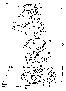
As best seen in FIGS. 2 and 3, dial mechanism 20 includes an
escutcheon plate 26, a base or ring member 28, a trim ring 30, a fastening
member 32, and dial 22. In particular, as best seen in FIG. 3, escutcheon
plate 26 includes an aperture 34 defined therein adapted to accept ring
member 28 and trim ring 30. Aperture 34 may be generally circular and
include an inner wall 36 and a ledge 38. Inner wall 36 of aperture 34 may
extend downwardly, and preferably perpendicularly, from an outer surface 40
of escutcheon plate 26. Further, ledge 38 may extend radially inwardly, and
preferably perpendicularly, from inner wall 36. One or more posts 42 may be
positioned on ledge 38 to assist in properly aligning ring member 28 on ledge
38. Escutcheon plate 26 may also have one or more alignment grooves 44
and snap openings 46 defined therein. Alignment grooves 44 are used to
properly align trim ring 30 within aperture 34, and snap openings 46 provide a
location for fastening member 32 to engage escutcheon plate 26. Further,
escutcheon plate 26 may include a handle aperture 48 that is adapted to
accept a handle 50, as best seen in FIG. 1. As best seen in FIG. 4, a
plurality
of posts 52 that extend outwardly from a back surface 54 of escutcheon plate
20 so that escutcheon plate 26 may be mounted to door 14 of safe 10.
As best seen in FIGS. 3 and 8, ring member 28 may be generally flat
and adapted to fit within aperture 34 and be supported by ledge 38. One or
more apertures 56 may be formed in a body 57 of ring member 28 and be
positioned to accept posts 52 for properly aligning ring member 28 on ledge
38. Also, ring member 28 may include an inner edge 58 and an outer edge
60. Outer edge 60 is adapted to fit within the aperture 34 formed in
escutcheon plate 26. Inner edge 58 may be circular and have three cut out
portions 62 defined therein. Each cut out portion 62 may have an arm 64
positioned therein, wherein each arm 64 includes a first portion 66 and a
second portion 68. First portion 66 extends radially inwardly from inner edge
58 of cut out portion 62 toward a center 69 of ring member 28 in generally the
same plane as body 57. Second portion 68 may extend perpendicularly from
first portion 66. Thus, arm 64 is generally an L-shaped member positioned
within cut out portion 62 and coupled with body 57. Due to the shape of arm
-4-
CA 02595310 2007-07-20
WO 2006/079050 PCT/US2006/002394
64 and the relatively flat profile of the ring member 28, arm 64 may flex or
bend relative to body 57 when a force is applied to second portion 68 of arm
64.
In addition, as best seen in FIGS. 3, 5, 6 and 8, second portion 68 may
include a protrusion or boss 70 that extends or protrudes outwardly from
second portion 68 and generally away from center 69. In addition, protrusion
70 includes contact surfaces 72 that are adapted to contact dial 22, which
will
be discussed in more detail below. Protrusions 70 may be cone-shaped,
semi-spherical or any other shape that will allow protrusion 70 to be
positioned between and in contact with adjacent teeth 100 on dial 22. The
present invention may include three arms 64 that contact dial 22 to equally
distribute the force imposed on dial 22 by arms 64 thereby properly balancing
dial 22 relative to ring member 28. However, as best seen in FIG. 9, it is
also
within the scope of the present invention to use a ring member 28' including
two arms 64 having two protrusions 70 in contact with dial 22. Furthermore, it
will be understood that the ring member may include only one arm or more
than three arms each having a protrusion in contact with the dial.
As best seen in FIGS. 3 and 5, trim ring 30 is generally ring-shaped
and adapted to fit within aperture 34 formed in escutcheon plate 26.
Specifically, trim ring 30 includes an outer surface 74 and an inner surface
76.
Outer surface 74 may include a plurality of alignment flanges 78 that are
adapted to fit within alignment grooves 44 defined in escutcheon plate 26 for
properly aligning trim ring 30 in aperture 34. With specific reference to FIG.
5,
outer surface 74 may also be adapted to contact inner wall 36 of aperture 34,
and inner surface 76 is positioned at a location between inner wall 36 and
protrusions 70 to allow dial 22 to come into contact with protrusion 70. As
best seen in FIG. 3, an indicator recess 80 is defined in trim ring 30 and
operates to accept and properly position indicator 25 relative to escutcheon
plate 26.
Fastening member 32 operates to fixedly mount and retain ring
member 28 and trim ring 30 to escutcheon plate 26. As best seen in FIG. 3,
fastening member 32 includes a main opening 82 adapted to allow dial 22 to
be positioned therein and trim ring 30 to be exposed. A handle aperture 84 is
defined therein and adapted to match handle aperture 48 defined in
-5-
CA 02595310 2007-07-20
WO 2006/079050 PCT/US2006/002394
escutcheon plate 26. Indicator 25 is mounted to fastening member 32 and
positioned so that it is adjacent to an outer circumference 86 of dial 22. In
particular, indicator 25 includes a point 88 that is aligned with the tick
marks
24 on dial 22. Fastening member 32 may also include a plurality of snap
arms 90 that may be inserted into snap openings 46 defined in escutcheon
plate 26 to securely fasten fastening member 32 to escutcheon plate 26.
As best seen in FIGS. 3, 4 and 7, dial 22 includes a base 92, a grip
portion 94 positioned on base 92, and a spindle 96 that extends from base 92.
Base 92 is adapted to fit within main opening 82 of fastening member 32.
Tick marks 24 may be positioned on an outer surface 98 and adjacent to outer
circumference 86 of base 92. Each of the tick marks 24 may generally
represent a numerical value that enables a user to enter a combination in
order to unlock safe 10. Tick marks 24 are generally located around the
entire outer circumference 86, but it will be understood that tick marks 24
may
only be positioned around a portion of outer circumference 86. Furthermore,
tick marks 24 may take the form of a line, dot or other type of marking on
dial
22 that will enable a user to enter a combination.
Furthermore, as best seen in FIGS. 5-7, a plurality of teeth or ridges
100 extend radially inward from an inner surface 102 of dial 22. One or more
of teeth 100 may be distributed about the entire, or a portion of, the inner
surface 102, each having a generally rounded end 104. At least a portion of
the contact surfaces 72 of protrusion 70 formed in ring member 28 are
adapted to be positioned between and in contact with adjacent teeth 100a,
100b, as best seen in FIG. 6.
As best seen in FIGS. 3, 4 and 7, spindle 96 extends outwardly from
back surface 54 of dial 22 and is coupled with a combination locking
mechanism so that dial 22 may rotate relative to escutcheon plate 26, ring
member 28, trim ring 30 and fastening member 32. The combination locking
mechanism operates to allow a user to open door 14 using handle 50 if the
correct combination of tick marks 24 are aligned with indicator 25 using dial
22 in the correct sequence. For instance, the locking mechanism shown and
described in U.S. Patent No. 6,131,428 to Wildman, which is hereby
incorporated by reference, may be coupled with spindle 96 to lock the safe 10.
-6-
CA 02595310 2007-07-20
WO 2006/079050 PCT/US2006/002394
In assembling dial mechanism 20, ring member 28 is placed in
aperture 34 formed in escutcheon plate 26 so that body 57 of ring member 28
is supported on ledge 38. Further, ring member 28 may be properly
positioned on ledge 38 by inserting posts 42 into apertures 56 formed in ring
member 28. Next, trim ring 30 is placed within aperture 34 and on top of ring
member 28 so that alignment flanges 78 are positioned within alignment
grooves 44 formed in escutcheon plate 28. Fastening member 32 is then
positioned on outer surface 40 of escutcheon plate 28 so that snap arms 90
are inserted within snap openings 46 formed in escutcheon plate 28. As snap
arms 90 are inserted into snap openings 46, indicator 25 is received within
indicator recess 80 formed in trim ring 30. Fastening member 32 is securely
mounted to escutcheon plate 26 and positioned over the alignment grooves
44 so that trim ring 30 and ring member 28 are secured to escutcheon plate
28. As best seen in FIGS. 5 and 6, dial 22 is then positioned within the main
opening 82 of fastening ring 32 so that teeth 100 are positioned between trim
ring 30 and arms 64 on ring member 28. Furthermore, at least a portion of
each contact surface 72 of the protrusions 70 are positioned between and in
contact with teeth 100a, 100b on dial 22. At this point, one of the tick marks
24 on dial 22 is aligned with point 88 on indicator 25 as best seen in FIG. 1.
Escutcheon plate 26 may then be mounted to door 14 of safe 10 using posts
52, and spindle 96 may be connected to the combination locking mechanism.
In operation, dial mechanism 20 may be used to enter a combination,
unlock the locking mechanism, and access the interior compartment of safe
10. In order to enter a combination, the user rotates the dial 22 to align the
tick marks 24 that correspond to the numbers in the combination with indicator
25. As best seen in FIG. 6, at least a portion of contact surfaces 72 on each
protrusion 70 are positioned between and in contact with a pair of adjacent
teeth 100a, 100b on dial 22 before dial 22 is rotated. In this position, one
of
the tick marks 24 is aligned with indicator 25. As dial 22 is rotated relative
to
ring member 28, protrusion 70 remains in contact with one of teeth 100b and
rides up the rounded end 104 of the tooth 100b, thereby causing arm 64 to
flex or bend radially inward in a direction 106. Arm 64 continues to flex or
bend radially inward until protrusion 70 reaches the apex of tooth 100b. After
moving past the apex of tooth 100, arm 64 will snap back so that contact
-7-
CA 02595310 2007-07-20
WO 2006/079050 PCT/US2006/002394
surfaces 72 of protrusion 70 are positioned between and in contact with an
adjacent pair of teeth 100b, 100c. Once protrusion 70 is positioned between
teeth 100b, 100c, a tick mark 24 corresponding to another number will be
aligned with indicator 25. The dial 22 may be rotated in this fashion until
the
desired tick mark 24 is aligned with indicator 25.
Each time arm 64 is positioned between a new set of teeth 100, a
clicking sound will be produced by the snapping action of arms 62 moving
from the apex of a tooth to a position where protrusion 70 is between and in
contact with a pair of adjacent teeth 100. The clicking sound may operate to
inform a user that a different tick mark 24 is aligned with indicator 25. It
will
be understood that arms 64 may be positioned equidistantly from one 'another
about ring member 28 to balance dial 22 by equally distributing the force
imposed on dial 22 by arms 64.
Protrusions 70 and teeth 100 are arranged such that each time contact
surfaces 72 on the protrusions 70 are positioned between and in contact with
teeth 100, a tick mark 24 on dial 22 is aligned with point 88 on indicator 25.
By positioning protrusions 70 between and in contact with teeth 100, the dial
22 will not have a tendency to remain in a position where indicator 25 is
pointing between tick marks. Instead, the arms 64 are biased so that they
have a tendency to be positioned between teeth and therefore align a tick
mark 24 with indicator 25. Therefore, dial mechanism 20 reduces the
possibility that a user will misread or be unable to determine which tick mark
24 is aligned with indicator 25.
The present invention overcomes and ameliorates the drawbacks and
deficiencies in the prior art. For instance, the dial mechanism of the present
invention includes a dial and ring member that operates to align the tick
marks
on the dial with an indicator. Further, the dial and ring member are rotatably
coupled with one another so that the dial makes a clicking sound to alert a
user each time a different tick mark is aligned with the indicator. By
aligning
the tick marks on the dial with the indicator and producing a clicking sound
when a new tick mark is aligned with the indicator, it is easier to identify
which
tick mark is being entered into the combination lock compared to existing
combination dial mechanisms. Thus, the present invention could reduce the
-8-
CA 02595310 2007-07-20
WO 2006/079050 PCT/US2006/002394
chance that an incorrect combination is entered and reduce the time it takes
to access the interior compartment of the safe.
Although the present invention has been described in considerable
detail with reference to certain preferred versions thereof, other versions
are
possible. Therefore, the spirit and scope of the appended claims should not
be limited to the description of the preferred versions contained herein.
All features disclosed in the specification, including the claims,
abstract, and drawings, and all the steps in any method or process disclosed,
may be combined in any combination, except combinations where at least
some of such features and/or steps are mutually exclusive. Each feature
disclosed in the specification, including the claims, abstract, and drawings,
can be replaced by alternative features serving the same, equivalent or
similar
purpose, unless expressly stated otherwise. Thus, unless expressly stated
otherwise, each feature disclosed is one example only of a generic series of
equivalent or similar features.
-9-