Note: Descriptions are shown in the official language in which they were submitted.
CA 02595644 2007-07-23
WO 2006/079468
PCT/EP2006/000362
A MULTIFUNCTION FINISHING ASSEMBLY FOR FLOOR COVERING,
A METHOD FOR MANUFACTURING AND A METHOD FOR LAYING SAID
ASSEMBLY
Technical field
The present invention relates to a
multifunction finishing assembly for floor covering,
which could be used in at least two different
applications, and preferably either as a joint bar
between two floor coverings or transition bar, or as a
joint bar between two floor coverings or stop bar, or
as a joint bar between two floor coverings or
transition bar or stop bar.
Prior art
In the field of floor covering laying or
renovation or floor renovation, it is of common
practice to use finishing elements in the form of
finishing bars, for example, made of wood, metal or
plastic, to be fixed to the floor, so as to cover the
edge of at least one floor covering. Amongst such
finishing elements there are predominantly joint bars,
transition bars, stop bars and step ridges. The
application for the finishing bar (joint bar,
transition bar, stop bar or step ridge) is determined
depending on its cross-sectional profile.
Finishing elements for floor covering of the
joint bar, transition bar, stop bar or step ridge type
are disclosed, for example, in Patent Applications
US2003/0154678 and U52004/0206038, and in US Patents
6,745,534, 6,805,951, 6,517,935, in French Patent
Applications FR 2,737,237, FR 2,848,234, FR 2,695,671,
CA 02595644 2007-07-23
WO 2006/079468
PCT/EP2006/000362
2
FR 2,783,854 and in International Patent Application WO
03/040492.
As used herein, the term "joint" bar refers
to a bar to be laid on the floor at the interface
between two adjacent floor coverings (moquette, carpet,
parquet, wooden floor, floor tilesõ). Such a bar type
generally has a T-shaped cross-sectional profile. Each
T wing is used for covering the edge of one of both
coverings and the T foot is used for fixing the bar to
the floor, for example by cooperation with a fixing
rail or similar permanently secured between both
coverings. Thus, the joint bar allows for the joint to
be masked between both floor coverings and for a better
aesthetics to be given to the transition zone between
both floor coverings. Moreover, the joint bar makes it
possible, as required, to compensate for and to mask
slight thickness differences between both floor
coverings.
As used herein, the term "transition" bar
refers to a bar being generally used for providing the
transition between a floor covering (moquette, carpet,
parquet, wooden floor, floor tiles, and the floor or
between two floor coverings with a significant height
offset. The function thereof is therefore to compensate
for and to mask significant height differences between
a floor covering and the floor or between two floor
coverings.
As used herein, the term "stop" bar refers to
a bar generally ending at the opposite side of the
floor covering with a substantially vertical side. Such
a bar type is generally used as a finishing element
CA 02595644 2007-07-23
WO 2006/079468
PCT/EP2006/000362
3
between a floor covering and a vertical wall such as a
wall or a partition.
The "step ridges" are bars having a L-shaped
cross-sectional profile and being intended for being
fitted on a step angle.
For improving the aesthetics and/or wear
resistance of floor covering finishing bars, it is
additionally known to apply on such bars, when being
manufactured, a surface coating which is, for example,
a film or a sheet of material glued with the top
surface of the bar. By way of an example, the above-
mentioned US Patents 6,805,951 and 6,517,935 describe a
method for manufacturing a finishing element comprising
a thin abrasion-resistant coating being of the
multilayer type.
More particularly with a view to simplify the
supply management and to offer to the customers a
single multiuse product, the finishing bar
manufacturers focussed these recent years on the
manufacture and marketing of multifunction finishing
bar assemblies of the kit type. A multifunction
finishing assembly is described for example in
International Patent Application WO 03/040492. In said
Publication, the multifunction finishing assembly
comprises a T-shaped joint bar onto which an additional
side bar is embedded. When the additional side bar is
assembled with the T-shaped element, the assembly can
be used as a transition bar (1st application). For
using the assembly as a joint bar 2nd application), it
is sufficient to separate the additional bar from the
CA 02595644 2012-07-23
WO .2006/079468
PCT/EP2006/000362
4
T-shaped bar, the latter being able to be used as a
joint bar.
One drawback of multifunction finishing
assemblies as known currently lies in the presence of a
small width longitudinal gap (interstice) at the
junction of the surfaces of the individual bars making
up the assembly. Not only does such a gap ruin the
aesthetic quality of the finishing assembly, but it
also deleteriously results in a brittleness area that
could be easily damaged over time and that gets dirty
more easily.
Objective of the invention
The objective of the present invention is to
provide a finishing assembly for floor covering being
of the multifunction type and overcoming the above-
mentioned drawback related to the presence of an
interstitial joint between each individual element of
the multifunction assembly.
Summary of the invention
As known, in the above-mentioned Publication
WO 03/040492, such a finishing assembly comprises at
least two bars, being on the one hand assembled
together side by side so that they comprise at least
two surfaces substantially in the prolongation of one
another, and separated by a longitudinal interstice,
and being, on the other hand, separable, said assembled
bars being designed to be used in a first floor
covering application and at least one of said bars
CA 02595644 2012-07-23
wo 2006/079468 PCT/EP2006/000362
=
being designed to be used in a second floor covering
application.
In a characteristic and novel way according
to the invention, the finishing assembly comprises a
5 floor covering being applied on said assembled bars and
covering the longitudinal interstice between said bars.
More particularly, the multifunction assembly
according to the invention comprises the additional and
optional technical features
said
technical features being, depending on the case,
considered separately or in combination one with the
others.
According to a another aspect of the
invention, the multifunction finishing assembly for
floor covering according to the invention comprises a
central bar having a substantially T-shaped cross
section, a monobloc assembly comprising two side bars
being connected together by a bridge and being
individually separable from the monobloc assembly, the
T-shaped central bar being embedded into the monobloc
assembly such that the foot of said T-shaped central
bar is positioned between both side bars and both wings
of the T-shaped bar abutting against both side bars. In
such a case, the finishing assembly preferably
comprises, but not necessarily, a surface coating being
applied on all the bars.
More particularly, the multifunction assembly
according to the invention comprises the following
additional and optional features considered separately
or in combination one with the others:
CA 02595644 2007-07-23
WO 2006/079468
PCT/EP2006/000362
6
- the finishing assembly comprises at least a fixing
rail able to cooperate with the T-shaped central bar
foot; more particularly, such a rail is mounted
integrally with the monobloc assembly, and
preferably, serves as a bridge connecting both side
bars together ; and
- the monobloc assembly is an extruded section.
A second object of the invention is a method
for manufacturing the above-mentioned finishing
assembly. According to the invention, such a method of
manufacturing comprises the following steps:
- manufacturing at least two distinct bars with the
same length;
- assembling said bars side by side such that they
have two surfaces substantially in the prolongation
one of the other and separated by a longitudinal
interstice; and
- applying on the bars a surface coating covering the
longitudinal interstice.
Preferably, during the manufacture, the bars
are temporarily maintained together for enabling the
application of the surface coating without moving the
bars one in respect to the other. More particularly,
when the method is related to the manufacture of a
finishing assembly comprising one central bar and two
side bars, an intermediate element is being
manufactured, said intermediate element consisting of
both side bars being connected together by a temporary
bridge.
Also, in a particular alternative of the
invention, a movable support pedestal is temporarily
CA 02595644 2007-07-23
WO 2006/079468
PCT/EP2006/000362
7
assembled with the bars, said pedestal allowing to
temporarily block said bars together in particular when
the assembly is being transported or handled.
A third object of the present invention is to
provide a method for laying onto the floor a
multifunction finishing assembly.
According to the invention, such a method
comprises a step wherein the surface coating is being
cut at the level of at least one longitudinal
interstice between two bars of the finishing assembly
so as to separate said both bars.
A fourth object of the invention is a cutting
tool comprising a shoe and a cutting blade being
integral with the shoe. The shoe is designed to be
positioned on the finishing assembly and to be able to
slide along such a finishing assembly while being
guided in translation by at least one side bar of said
assembly. The cutting blade is positioned and oriented
relative to such a shoe, such that once the shoe
positioned on the finishing assembly, the cutting blade
allows the surface coating to be cut through
translation of the shoe along the finishing assembly.
Brief description of the drawings
Other features and advantages of the
invention will be more clearly apparent on reading the
herein below detailed description of several preferred
alternative finishing assemblies according to the
invention, such a description being set forth as a non
limitative and non exhaustive example of the invention
and referring to the appended drawings wherein:
CA 02595644 2007-07-23
WO 2006/079468
PCT/EP2006/000362
8
- Fig. 1 is a perspective view of a first alternative
embodiment of a multifunction finishing assembly
(joint bar/transition bar/stop bar) comprising a
section forming a movable pedestal temporarily
connecting the side bars of the multifunction
assembly and additionally comprising a U-shaped
fixing rail,
- Fig. 2 is a perspective view of the T-shaped central
bar of the assembly as shown on Fig. 1,
- Fig. 3 is a perspective view of an intermediate
section comprising both side bars of the assembly as
shown on Fig. 1, connected by a separable temporary
bridge,
- Fig. 4 is a perspective view of the T-shaped central
bar of Fig. 2 assembled with the intermediate
section as shown on Fig. 3,
- Fig. 5 is a perspective view of the assembly as
shown on Fig. 4 after application of the surface
coating onto the bars,
- Fig. 6 is a perspective view of the assembly shown
on Fig. 5 after cutting the temporary bridge
connecting the side bars,
- Fig. 7 is a perspective view of the pedestal of the
multifunction assembly as shown on Fig. 1,
- Figs. 8, 9 and 10 show applications of the
multifunction assembly shown on Fig. 1 respectively
as a joint bar, a transition bar and a stop bar,
- Fig. 11 is a perspective view of a second
alternative embodiment of a multifunction finishing
assembly (joint bar/transition bar/stop bar),
CA 02595644 2007-07-23
WO 2006/079468
PCT/EP2006/000362
9
- Fig. 12 is a perspective view of a third alternative
embodiment of a multifunction finishing assembly
(joint bar/transition bar/stop bar),
- Fig. 13, 14 and 15 show applications of the
multifunction assembly shown on Fig. 12 respectively
as a joint bar, a transition bar and a stop bar,
- Fig. 16 is a perspective view of a .fourth
alternative embodiment of a multifunction finishing
assembly (joint bar/transition bar/stop bar),
- Figs. 17, 18 and 19 shown applications of the
multifunction assembly shown on Fig. 16 respectively
as a joint bar, a transition bar and a stop bar,
- Fig. 20 is a perspective view of a fifth alternative
embodiment of the multifunction finishing assembly
(joint bar/transition bar/stop bar),
- Fig. 21 is a perspective view of two U-shaped fixing
rails one embedded into the other and separable,
said rails being intended to be used for fixing to
the floor the finishing assembly shown on Fig. 20,
- Fig. 22 shows the multifunction assembly shown on
Fig. 20 used as a joint bar,
- Figs. 23 and 24 respectively show two different
applications of the multifunction assembly shown on
Fig. 20 as a transition bar,
- Figs. 25 and 26 respectively show two different
applications of the multifunction assembly shown on
Fig. 20 as a stop bar,
- Fig. 27 is a perspective view of a sixth embodiment
of a multifunction finishing assembly (joint
bar/transition bar/stop bar),
CA 02595644 2007-07-23
WO 2006/079468
PCT/EP2006/000362
- Fig. 28 is a perspective view of two fixing rails
respectively with U-shaped and T-shaped, one
embedded into the other and separable, said rails
being intended to be used for fixing to the floor
5 the finishing assembly shown on Fig. 27,
- Fig. 29, 30, and 31 show applications of the
multifunction assembly as shown on Fig. 12
respectively as a joint bar, a transition bar and a
stop bar,
10 - Fig. 32 is a perspective view of a seventh
alternative embodiment of a multifunction finishing
assembly (joint bar/transition bar/stop bar) and of
a tool for cutting the surface coating, and
- Fig. 33 shows the cutting tool in a cutting position
on the finishing assembly shown on Fig. 32.
Detailed description
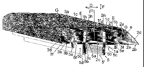
On Fig. 1 there is shown a finishing assembly
for a floor covering according to a first preferred
embodiment of the invention, and which could be used in
three different applications either as a joint bar, a
transition bar or a stop bar.
Such a finishing assembly consists in five
elements:
- three finishing bars, with the same length, and for
example, made of wood, namely a central bar 1, and
two side bars 2 and 3 arranged on both sides of the
central bar,
- a surface coating 4 applied onto the three finishing
bars 1, 2 and 3, and
- a pedestal 5, for example, in plastic.
CA 02595644 2007-07-23
WO 2006/079468
PCT/EP2006/000362
11
The two side bars 2 and 3 have different
cross-sectional profiles (i.e., in a plane
perpendicular to their longitudinal axis).
When being used on its own, the finishing bar
1 is a joint bar (15t application). Both bars 1 and 2,
when they are used together, form a transition bar (2nd
application). Both bars 1 and 2, when being used
together, form a stop bar (3rd application).
In particular, in the illustrated example,
the joint bar 1 is symmetrical according to a median
longitudinal plane (P) and has a T-shaped cross
section, with a central pedestal la, and two side wings
lb and 1C being identical and symmetrical with one
another relative to the plane P. The bar 1 comprises a
top surface ld being planar in its central part and
having a circle arc-shaped curve at the level of both
wing lb and lc ends.
The side bar 2 is a distinct part of the
above-mentioned bar 1 and is positioned side by side
with the bar 1 between the central foot la and the wing
lb. The bar 2 comprises a top face 2a, being partially
in contact with the bottom face of the wing lb, a
bottom face 2b, an internal side face 2c directed to
the central foot la of the bar 1 and a slightly curve
external side face 2d. The external side face 2d of the
bar 2 lies in the extension of the top face id of the
central bar 1, a longitudinal interstice 6 separating
both faces id and 2d throughout the length of the bars
1 and 2.
The bar 3 is a part distinct from the above-
mentioned bar 1 and is positioned side by side with the
CA 02595644 2007-07-23
WO 2006/079468
PCT/EP2006/000362
12
bar 1 between the central foot la and the wing lc. The
bar 3 comprises a top face 3a, partially coming in
contact with the internal face of the wing lb, a bottom
face 3b, an internal side face 2c directed toward the
central foot la of the bar 1, and an external side face
3d being substantially planar and perpendicularly
directed toward the planar central part of the top face
ld of the bar 1. The external side face 3d of the bar 2
lies in the prolongation of the top face ld of the
central bar 1, a longitudinal interstice 6' separating
both faces ld and 3d throughout the length of the bars
1 and 3.
The surface coating 4 is a flexible
rectangular-shaped sheet of material (monolayer or
multilayer), being applied and fixed through any known
means and for example, through gluing by means of an
adhesive, on the top face ld of the bar 1 and on the
external side faces 2d and 3d respectively of the bars
2 and 3. The surface coating 4 covers all the above-
mentioned surfaces ld, 2d, and 3d, and essentially
covers and masks advantageously the two longitudinal
interstices 6 and 6'. The three bars 1, 2 and 3 are
thus retained together through such a surface coating
4.
More generally, within the scope of the
invention, the "surface coating" of the finishing
assembly may comprise any coating having a thin
thickness being able to match the curved surface of the
individual bars on the finishing assembly, whatever the
nature of the material (s) making up the coating and
whatever the technique used for applying the coating on
CA 02595644 2007-07-23
WO 2006/079468
PCT/EP2006/000362
13
the bars of the finishing assembly. In particular, the
coating could indiscriminately be of the monolayer or
of the multilayer type. It could for example comprise a
film or a sheet, made in plastic, in paper, in wood, or
be made in any known fabric (non woven, woven fabric).
Preferably, but not necessarily, the coating will be
decorative and/or will have improved mechanical wear
resistant properties. Preferably, but not necessarily,
the surface coating is glued (cold or heat glued) on
the bars of the finishing assembly.
The pedestal 5 is a section, preferably made
in plastic, with the same length as the bars 1, 2 and
3. It comprises a base plate 5a and two identical,
parallel longitudinal walls 5b, substantially
perpendicular to the base plate 5a. Those both walls 5b
form together with the base plate 5a, a U-shaped rail
5', for fixing on the floor the bar(s) of the finishing
assembly.
In the particular alternative embodiment of
Fig. 1, the pedestal 5 further comprises two side wings
5c extending the base plate 5a on both sides of the U-
shaped fixing rail 5'. Each side wing Sc is separable
relative to the U-shaped rail 5'. Preferably, in order
to facilitate the separation through cutting each side
wing Sc, a V-shaped longitudinal groove 5d is provided
at each joint between the U-shaped fixing rail 5' and
each side wing 5c, said V-shaped groove 5d making up a
separation line with a lower thickness.
More particularly, both side bars 2 and 3
comprise respectively in the lower sides 2b, 3b thereof
two longitudinal grooves 2e and 3e. Each side wing Sc
CA 02595644 2007-07-23
WO 2006/079468
PCT/EP2006/000362
14
of the pedestal 5 ends at a longitudinal retaining stud
5e being designed to be embedded, preferably by
tightening, into one of the grooves 2e or 3e.
More particularly, each wing 5c of the
pedestal 5 comprises an additional longitudinal stud 5f
being separable. Referring to Fig. 1, the additional
studs 5f are housed into the two above-mentioned
longitudinal grooves 2e and 3e, such that the pedestal
5 is temporarily assembled with the two side bars 2 and
3. Preferably, both studs 5f are slightly resiliently
flexible relative to the base plate 5a, such that the
pedestal 5 is made integral through nipping of the bars
1, 2 and 3 between both temporary studs 5f.
In the embodiment on Fig. 1, the pedestal 5
advantageously makes it possible to block in position
the side bars 2 and 3 abutting against the bar 1, and
more particularly prevents the side bars 2 and 3 from
moving relative to the side bar 1 in a plane parallel
to the cross-section of the bars. The assembly 1, 2, 3,
4 and 5 thus makes up a ready-to-use multifunction
finishing assembly, able to be advantageously easily
handled and/or transported and/or offered for sale.
When being offered for sale, such an assembly could be
obviously wrapped with the user's guide, in a
transparent plastic wrap.
In particular, in the alternative embodiment
shown on Fig. 1, the bottom face le of each wing lb and
lc of the central bar 1 comprises a blocking
longitudinal groove if forming a double abutment, into
which is positioned a projecting longitudinal part 2f
or 3f of the bar 2 or 3. Said projecting part 2f or 3f
CA 02595644 2007-07-23
WO 2006/079468
PCT/EP2006/000362
allows to laterally block in translation the side bar 2
or 3 relative to the central bar 1 following an axis D
perpendicular to the median longitudinal plane P of the
bar 1.
5 Preferably, the side faces lg of the central
foot la of the bar 1 comprise a longitudinal groove lh
forming a double abutment, into which is to be arranged
a projecting longitudinal part 2h (respectively 3h) of
the bar 2 (respectively the bar 3), allowing the bar 2
10 (respectively the bar 3) to be blocked in translation
relative to the foot la of the bar 1 in a plane
parallel to its cross sectional section and along an
axis F perpendicular to the above-mentioned axis D.
Preferably, the thickness (e) of the
15 projecting longitudinal part 2h (respectively 3h) of
the bar 2 (respectively the bar 3) is lower than the
height (h) of the groove lh such that there should be,
between the bar 2 (respectively the bar 3) and the bar
1, a slight play advantageously allowing for a slight
motion of the bar 2 (respectively bar 3) relative to
the bar 1 in a plane parallel to the cross-section of
the bars. The utility of such a clearance will be more
clearly obvious referring to Fig. 26.
Advantageously, the projecting longitudinal
parts 2h and 3h allow on both sides of the foot la of
the central bar 1, for providing a longitudinal space E
being able to serve as a housing for the walls 5b of
the fixing rail 5' of the pedestal 5.
According to an additional preferred feature,
the side bar 2 (respectively the side bar 3) comprises
a longitudinal recess 2i (respectively 31) extended
CA 02595644 2007-07-23
WO 2006/079468
PCT/EP2006/000362
16
throughout the length of the bar and being arranged
opposite to the bottom face of the wing lb
(respectively wing 1c) of the bar 1. Such a recess 2i
(respectively 3i) delimits with the bottom face of the
wing lb (respectively wing 1c) of the bar 1, a groove G
with a low width (1) allowing a cutting blade to be
inserted and guided. The entry of such a groove G
corresponds to the interstice 6 or 6'. Practically, the
width (1) of the groove will be preferably higher than
0.6 mm.
Fig. 2 to 7 illustrate the main successive
steps for manufacturing the finishing assembly of
Fig. 1.
Step 1 (Fig. 2 and 3)
The joint bar 1 and the intermediate part I
are manufactured with two bars 2 and 3 connected
throughout their length by a separable temporary
longitudinal bridge P. Depending on the material type,
such parts 1 and I are manufactured, for example,
through machining (wooden parts) or through extrusion
(plastic or metal parts).
Step 2 (Fig. 4)
Through a simple embedment, the bar 1 is
interfitted with the intermediate part I, the foot la
of the bar 1 being housed into the longitudinal space
delimited by both external side faces 2c and 3c
opposite the bars 2 and 3 and by the temporary bridge
P. During this assembling operation, the projecting
parts 2f and 3f of the bars 2 and 3 are housed in the
corresponding grooves lf of the bar 1, allowing the bar
2/bar 3/temporary bridge P assembly to be centred
CA 02595644 2007-07-23
WO 2006/079468
PCT/EP2006/000362
17
relative to the bar 1. As a result, the bars 2 and 3
are perfectly positioned and maintained in position
relative to the bar 1 during the subsequent application
operation of the surface coating 4 (Step 3/Fig. 5).
Step 3 (Fig. 5)
The surface coating 4 is applied and glued on
the assembly formed by the parts 1 and I, so as to
totally cover the faces ld, 2d and 3d of the bars 1, 2
and 3. The application and gluing technique of such a
coating is known per se and will therefore not be
detailed in the present application. The temporary
bridge P advantageously makes it possible to maintain
the bars 2 and 3 relative to the bar 1 during the
application operation of the surface coating 4.
Once applied, the surface coating 4
advantageously masks both interstices 6 and 6'.
Step 4 (Figs. 5 and 6)
The temporary bridge P connecting the bars 2
and 3 is removed by cutting it using a cutting tool
(for example, a cutting blade (Fig. 5) or a saw), so
that the bars 2 and 3 are no longer directly integral
with one another (Fig. 6). The bars 1, 2 and 3 are
maintained together by the surface coating 4.
Step 5 (Figs. 7 and 1)
The pedestal 5, being previously manufactured
(Fig. 7) for example through extrusion, is assembled
with the previously formed bar 1/bar 2/bar 3/coating 4
assembly, so as to form the finishing assembly as shown
on Fig. 1. Such an assembly operation could be simply
achieved embedding or interfitting the side bars 2 and
3 onto separable temporary studs 5f of the pedestal 5.
CA 02595644 2007-07-23
WO 2006/079468
PCT/EP2006/000362
18
In such a configuration of Fig. 1, the pedestal 5
advantageously allows the above-mentioned temporary
bridge P to be replaced, mechanically connecting both
bars 2 and 3 together, and maintaining them applied on
the central bar 1. The finishing assembly shown on
Fig. 1 could thus be handled without risking to move
the bar 2 or the bar 3 relative to the bar 1 and
thereby without risking to damage the coating 4.
The various usage possibilities of the
finishing assembly according to Fig. 1 will now be
detailed referring to Figs. 8 to 10.
Use as a joint bar (Fig. 8)
On Fig. 8 there is shown the implementation
of the central bar 1 of the assembly as in Fig. 1 as a
joint bar, interposed between both floor coverings R1
and R2 having substantially the same height H relative
to the floor. It could be any known type of floor
covering (wooden floor, moquette, carpet, parquet,
wooden floor, floor tiles, linoleum, In order to
achieve the implementation of Fig. 8, it is sufficient
for the final user having the finishing assembly shown
on Fig. 1 to perform the following operations.
The pedestal 5 is released from the bars 2
and 3 of the finishing assembly. The pedestal 5 is cut
along both V-shaped grooves 5d so as to only keep the
U-shaped fixing rail 5'. The coating 4 is cut using a
blade or similar, along each longitudinal groove G, so
as to separate the side bars 2 and 3 (and their surface
coating 4 portion), from the central bar 1 and its
surface coating 4 portion. The width (1) of each
interstice 6, 6' being sufficient for sliding a cutting
CA 02595644 2007-07-23
WO 2006/079468
PCT/EP2006/000362
19
blade into the groove G, advantageously a sharp cutting
of the coating 4 is achieved.
Subsequently, the base 5a of the U-shaped
fixing rail 5' is fixed to the floor between both
coverings R1 and R2, using any appropriate means
selected more specially depending on the nature of the
floor (for example, screwing and/or gluing). The
central foot la of the bar 1 is inserted into both arms
5b of the rail 5' and pushing it until both wings lb
and 1 of the bar come into contact with the surface of
both coverings R1, R2. Preferably, the internal side of
both arms 5b is notched so as to allow the joint bar 1
to be blocked in position at different heights,
depending on the height H of the coverings.
Use as a transition bar (Fig. 9)
There is shown on Fig. 9, the implementation
of the finishing assembly of Fig. 1 as a transition bar
between a floor covering R and the floor underlying
such a floor covering. In order to achieve the
implementation of Fig. 9, it is sufficient for the
final user having the finishing assembly shown on Fig.
1 to perform the following operations.
The pedestal 5 is released from the bars 2
and 3 of the finishing assembly. The pedestal 5 is cut
manually along one of the V-shaped grooves 5d so as to
only keep the U-shaped fixing rail 5' and a side wing
5c, the other side wing 5c being removed. The temporary
stud 5f is cut from the remaining wing 5c.
The coating 4 is cut manually using a blade
or similar, slid into the groove G, so as to separate
the side bar 3 (and its surface coating 4 portion),
CA 02595644 2007-07-23
WO 2006/079468
PCT/EP2006/000362
from the remaining assembly: bar 1/bar 2/coating 4
covering the bars 1 and 2.
Subsequently, the base 5a of the U-shaped
fixing rail 5' is fixed to the floor along the covering
5 R edge using any appropriate means selected more
specially depending on the nature of the floor (for
example, screwing and/or gluing).
The foot la of the central bar 1 is inserted
between the U-shaped rail 5' and the longitudinal
10 retaining stud 5e into the bottom groove 2e of the bar
2. The bar 1/bar 2/coating 4 assembly is pushed until
the wing lc of the bar 1 comes into contact with the
covering R surface.
Use as a stop bar (Fig. 10)
15 There is shown on Fig. 10 the implementation
of the finishing assembly of Fig. 1 as a stop bar
between a floor covering R and the floor underlying
such a floor covering. In order to achieve the
implementation of Fig. 9, it is sufficient for the
20 final user having the finishing assembly shown on Fig.
1 to perform the same operations as previously
described for applying the transition bar, but
substituting in the explanations bar 3 for bar 2.
Referring to Fig. 9 (transition bar) and to
Fig. 10 (stop bar), it is understood that the coating 4
covering the interstitial joint 6 and 6' respectively,
it advantageously allows to protect it against any
fouling and to mask it, improving the aesthetics of the
finishing. In addition, any releasing or damaging risk
of the surface coating 4 is prevented at the level of
CA 02595644 2007-07-23
WO 2006/079468
PCT/EP2006/000362
21
the joint between both bars 1 and 2, or between the
bars 1 and 3.
There is shown on Fig. 11 another further
embodiment of the finishing assembly according to the
invention, being distinct from the finishing assembly
shown on Fig. 1, due to the absence of the pedestal 5
and of the presence of a temporary bridge P connecting
between one another both side bars 2 and 3. At the
joint between such a bridge and respectively both bars
2 and 3 are arranged V-shaped longitudinal grooves 2g
and 3g. The bridge P is to be used for fixing to the
floor, for example, through gluing or screwing, the bar
2 or the bar 3 depending on the selected application
(transition bar or stop bar) after the other bar unused
in the application has been separated from the bridge
P.
There is shown on Fig. 12 a third alternative
embodiment of a finishing assembly according to the
invention. In such an alternative, the side faces lg of
the central foot la of the T-shaped central bar 1 are
notched so as to allow the foot la to be adjusted in
height in the U-shaped fixing rail 5'.
Figs. 13, 14 and 15 show the finishing
assembly of Fig. 12, respectively used as a joint bar,
a transition bar and a stop bar.
There is shown on Fig. 16 a fourth
alternative embodiment of a finishing assembly
according to the invention. In such an alternative, the
bars 2 and 3 as well as the U-shaped fixing rail 5' are
integrally part of a sole monobloc assembly 7. Such a
CA 02595644 2007-07-23
WO 2006/079468
PCT/EP2006/000362
22
monobloc assembly 7 is preferably a plastic extruded
section.
Figs. 17, 18 and 19 show the finishing
assembly of Fig. 16 respectively used as a joint bar, a
transition bar and a stop bar. It is to be noted that
for Figs. 18 and 19, the bars 2 and 3 were previously
separated through cutting the U-shaped rail 5'.
There is shown on Fig. 20 a fifth alternative
embodiment of a finishing assembly according to the
invention, being intended to be used with both U-shaped
fixing rails 8 and 9 shown on Fig. 21. The rail 8 is a
U-shaped section having its side walls 8b notched on
their internal faces. The rail 9 is a U-shaped section
having its side walls 9b notched on their external and
internal faces. The rail 9 could additionally be
embedded into the rail 8 and adjusted in height
relative to the rail 8 in cooperation of its external
notches 9c with the internal notches 8c of the rail 8.
Fig. 22 shows the finishing assembly of
Fig. 20 configured as a joint bar and fixed to the
floor at the joint between both coverings R1 and R2
using both embedded rails of Fig. 21.
Fig. 23 shows the finishing assembly of
Fig. 20 configured as a transition bar and used for a
transition between the floor covering R and the floor,
said finishing assembly being fixed to the floor by
means of the rail 9 only.
Fig. 24 shows the finishing assembly of
Fig. 20 configured as a transition bar and fixed for a
transition between both floor coverings R1 and R2
having a significant offset in height one relative to
CA 02595644 2007-07-23
WO 2006/079468
PCT/EP2006/000362
23
the other. In such an application, the finishing
assembly is fixed to the floor by means of both
embedded rails 8 and 9.
Fig. 25 shows the finishing assembly of
Fig. 20 configured as a stop bar and used for a
transition between a floor covering R and the floor,
said finishing assembly being fixed to the floor by
means of the rail 9 only.
Fig. 26 shows the finishing assembly of
Fig. 20 configured as a stop bar and used for a
transition between a floor covering R and the floor,
said finishing assembly being fixed to the floor by
means of both embedded rails 8 and 9. In the
application as illustrated on said figure, both rails 8
and 9 are off-centred one relative to the other, the
base 9a of the rail 9 being not parallel to the base 8a
of the rail 8 but forming with said base 8a an angle A,
so as to allow the level to be compensated for between
the floor and the covering R. Such a rail 9 tilting
relative to the rail 8 is achieved slightly forcibly
deforming the side branches 8b of the U-shaped rail 8
relative to its base 8a. In addition, it is to be noted
that in such an embodiment (as well as the alternative
embodiments shown on Fig. 1 and on Fig. 16), such a
tilting is achievable by means of some play existing
between the groove lh and the projecting part 3h of the
bar 3 (slightly lower dimension (e) at the level (h) of
the groove 1h), said play allows the bar 3 to be moved
relative to the bar 1, in a plane parallel to the
cross-section of the bars.
CA 02595644 2007-07-23
WO 2006/079468
PCT/EP2006/000362
24
There is shown on Fig. 27 a sixth alternative
embodiment of a finishing assembly according to the
invention, being intended to be used with both fixing
rails 10 and 11 of Fig. 28.
The rail 11 comprises a U-shaped section. The
rail 10 comprises a T-shaped section and can be
embedded at various heights into the U-shaped section
11.
In the finishing assembly of Fig. 27, the
foot la of the T-shaped bar 1 comprises a longitudinal
groove 1 allowing for said bar to be embedded onto the
foot 10b of the T-shaped rail 10. Both side bars 2 and
3 are connected to one another by a separable temporary
bridge P, being intended to be cut when the finishing
assembly is being arranged on the floor.
Fig. 29 shows the finishing assembly of
Fig. 27 configured as a joint bar and used for a
transition between both floor coverings R1 and R2. In
such an application, the finishing assembly is fixed to
the floor using two rails 10 and 11 one embedded into
the other, the groove li of the T-shaped central bar 1
being embedded into the T-shaped fixing rail 10, and
the rail 11 being fixed using any other means (gluing,
screwing,...).
Fig. 30 shows the finishing assembly of
Fig. 27 configured as a transition bar and used for a
transition between a floor covering R and the floor,
said finishing assembly being fixed to the floor by
means of both embedded rails 10 and 11. In such an
application, the bars 1 and 2 are spaced apart from one
another in a plane parallel to their cross-sections,
CA 02595644 2007-07-23
WO 2006/079468
PCT/EP2006/000362
the base 10a of the T-shaped rail 10 being tilted
relative to the base 11a of the U-shaped rail 11.
Similarly to the application on Fig. 26, such a tilting
is achievable by means of some play existing between
5 the groove 1h and the projecting part 2h of the bar 2,
said play allows the bar 2 to be moved relative to the
bar 1, in a plane parallel to the cross-section of the
bars.
Fig. 31 illustrates the finishing assembly of
10 Fig. 27 configured as a stop bar and used for a
transition between a floor covering R and the floor,
said finishing assembly being fixed to the floor by
means of the T-shaped fixing rail 10 only.
There is shown on Fig. 32 a seventh
15 alternative embodiment of a multifunction finishing
assembly (1, 2, 3, 4) according to the invention and a
cutting tool 12. Fixing to the floor of such a
finishing assembly occurs by means for example of at
least one fixing rail (not shown on Fig. 32) into which
20 is embedded the foot of the central bar 1, similarly to
what has been previously described for the six other
alternative embodiments on Figs. 1 to 31.
The cutting tool 12 comprises a shoe 12a and
a cutting blade 12b integral with said shoe 12a. The
25 foot 12 is for example a plastic moulded part. The shoe
12a comprises a face 12c (referred to as the bottom
face) having a U-shaped recess shape. Said bottom face
12c allows the shoe to be positioned on the finishing
assembly (1, 2, 3, 4) and said shoe 12a to be guided in
translation by both side bars 2 and 3 along the
longitudinal axis of the finishing assembly. The
CA 02595644 2007-07-23
WO 2006/079468
PCT/EP2006/000362
26
cutting blade 12b is positioned and oriented relative
to the shoe 12a, such that once the shoe 12a being
positioned on the finishing assembly (1, 2, 3, 4), the
cutting blade 12b penetrates into one of the
longitudinal grooves G of the finishing assembly.
There is shown on Fig. 33 the cutting tool 12
positioned on the end of the finishing assembly shown
on Fig. 32. The cutting blade 12b partially penetrates
into the longitudinal groove G between the central bar
1 and the side bar 2. By sliding the tool 12 along the
finishing assembly (arrow F), the surface coating 4 is
very easily and very accurately cut along said
longitudinal groove G, allowing to separate the section
2 from the central section 1. For separating, as
required, the other section 3 from the central section
1, it is sufficient to reverse the positioning of the
cutting tool 12, so that the cutting blade 12b
penetrates into the longitudinal groove G between the
central blade 1 and the side bar 3.
A similar cutting tool could be used for
cutting the surface coating 4 of the other previously
described alternative embodiments of finishing
assembly.
The present invention is not limited to
manufacturing a multifunction assembly comprising three
bars 1, 2 and 3, but could be generalized so as to
achieve a multifunction finishing assembly comprising
at least two bars, onto which is applied the same
surface coating. For example, a multifunction assembly
could be achieved only comprising one T-shaped bar 1
and one bar 2 and usable as a joint bar or a transition
CA 02595644 2007-07-23
WO 2006/079468
PCT/EP2006/000362
27
bar as well as a multifunction assembly comprising only
one T-shaped bar 1 and one bar 3, and usable as a joint
bar or a stop bar.
In addition, the cross-sections of the bars
of the finishing assemblies of the appended figures
were given only by way of non exhaustive examples of
embodiments, the invention being not limited to these
only sections. The invention could be equally applied
for achieving multifunction finishing assemblies for
floor covering having their bars with cross-sections
different from those illustrated on the appended
figures. Moreover, the bars of the finishing assembly
of the invention, depending on their cross-sections,
could, as required, fulfil other functions than the
functions illustrated on the figures (joint bar,
transition bar or stop bar). Within the scope of the
invention, a finishing assembly could be achieved for a
floor covering being able to be used in other
applications for floor covering, and for example, that
could be configured for a use as a step ridge.