Note: Descriptions are shown in the official language in which they were submitted.
CA 02595831 2007-07-24
WO 2006/082571
PCT/1E2006/000006
1
"A device for vaporising vaporisable matter"
The present invention relates to a device for vaporising vaporisable matter to
produce an aerosol for inhaling. For example, the device is suitable for
vaporising
vaporisable matter which comprises one or more of flavour constituents,
medicinal
constituents and psychoactive constituents, such as tobacco, mullein, passion
flower, cloves, yohimbe, mint, tea, eucalyptus, camomile and other such herbs
and
plant matter. The device is also suitable for use for vaporising medicinal
compounds
to form an aerosol for inhaling for rapid absorption into the bloodstream.
Herbs, for example, tobacco and the like are smoked by burning, in order to
release
psychoactive constituents, which are then inhaled. The psychoactive
constituents
are released into the fumes of combustion, which are then inhaled. However,
the
burning of such herbs, as well as producing psychoactive constituents also
produces
toxins, which largely result from the actual combustion process. Such toxins
may be
carcinogenic, and/or may result in lung and heart disease. Thus, the smoking
of
such herbs and other such plant matter is hazardous and undesirable, for
example, it
is now well established that smoking tobacco products, such as cigarettes can
lead
to lung and heart disease.
An alternative to releasing flavour, medicinal and psychoactive constituents
from
such herbs and plant matter by smoking is to raise the temperature of the herb
or
plant matter to an appropriate temperature for causing the vaporisable
constituent or
constituents of the herb or plant matter to be vaporised to produce an
aerosol, and
then inhale the aerosol. However, the temperature range at which such
constituents
in herbs and plant matter can be vaporised to form an aerosol ranges from
approximately 125 C to 400 C. If the temperature is below 125 C, in general,
an
aerosol of the constituent or constituents is not produced. However, if the
temperature to which the herb or plant matter is heated exceeds 400 C,
combustion
of the herb or plant matter may commence, and additionally, undesirable
constituents and toxins may be vaporised. Additionally, the desirable
constituents of
tobacco, in general, vaporise at temperatures in the range of 125 C to 400 C,
and in
=
CA 02595831 2012-10-26
2
particular at temperatures in the range of 130 C to 250 C, while the
undesirable constituents
may commence to vaporise at temperatures in excess of 250 C. In general, some
undesirable constituents of tobacco tend to vaporise to produce an aerosol at
temperatures
above 250 C, and in general, undesirable constituents tend to be vaporised
from tobacco at
temperatures in excess of 400 C. Thus, it is desirable to maintain the tobacco
at a
temperature in the range of 130 C to 250 C in order to produce an aerosol of
the desirable
constituents, and to prevent an aerosol of the undesirable constituents of
tobacco being
produced. Thus, in order to satisfactorily produce an aerosol of flavour,
medicinal and
psychoactive constituents in herbs and plant matter, the temperature at which
the herb or
plant matter is maintained for producing the aerosol must be controlled within
reasonably
tight tolerances.
It is known to provide apparatus for vaporising constituents of herbs, such as
tobacco to
produce an aerosol. Such apparatus may be electrically powered or gas powered.
Electrically powered apparatus, in general, comprise an electrically powered
heating element
for heating the tobacco or herb to a desired temperature in a vaporising
chamber to produce
the aerosol. A tube extending from the vaporising chamber accommodates the
aerosol to a
mouthpiece for facilitating inhaling of the vaporised constituents. Such an
electrically
powered device for vaporising constituents of tobacco is illustrated in U.S.
Patent
Specification No. 5,144,962.
While such devices may be powered by a battery, in general, the power
requirement for
providing sufficient heat for maintaining the tobacco or herb at the
appropriate temperature to
produce an aerosol is relatively high, thus leading to relatively short
battery life. In general,
to overcome this problem, such devices are powered by mains electricity.
However, a
serious disadvantage of powering such devices with mains electricity is that
they are
effectively no longer portable, since one can only use the devices in the
presence of a supply
of mains electricity.
Gas powered devices for producing an aerosol from tobacco and other such herbs
CA 02595831 2007-07-24
WO 2006/082571
PCT/1E2006/000006
3
and plant matter tend to overcome the lack of portability problem of mains
electrically
powered devices, since in general a fuel gas supply can be stored in an
associated
reservoir under pressure in liquid form, and a reasonable life can be obtained
from a
charge of liquefied gas in a relatively small size reservoir. Such gas powered
devices heat the tobacco or other herb by flame combustion or by catalytically
converting the fuel gas to heat. However, in general, the temperature at which
fuel
gas is converted to heat either by flame combustion or catalytic conversion
tends to
be relatively high, and in the case of catalytic conversion, in general,
catalytic
combustion elements tend to operate at temperatures in the range of 600 C to
900 C and more commonly at temperatures in the range of 800 C to 900 C. Thus,
in general, in such gas powered devices the tobacco tends to be heated to
temperatures considerably greater than the desired temperature range of 130 C
to
250 C, and commonly the tobacco may be heated at temperatures up to and in
excess of 400 C. This is undesirable, since heating tobacco to such high
temperatures can lead to combustion of the tobacco, and furthermore, at such
high
temperatures undesirable toxic constituents are also vaporised and become
entrained in the aerosol. Examples of gas powered vaporising devices are
disclosed
in U.S. Patent Specification No. 5,944,025 of Cook, et al assigned to Brown &
Williamson Tobacco Company and U.S. Patent Specification No. 6,089,857 of
Matsuura, et al assigned to Japan Tobacco Inc. U.S. Patent Specification No.
5,944,025 discloses an elongated tubular member which comprises a vaporising
chamber in which tobacco, constituents of which are to be vaporised to produce
an
aerosol, is located. Air is drawn through a reservoir containing an absorbent
material impregnated with a liquid fuel for mixing vapour of the liquid fuel
with the air.
The fuel/air mixture is drawn through a catalyst coated ceramic tube where the
fuel/air mixture is converted to heat by a catalytic reaction. Hot exhaust
gases from
the catalytic reaction are drawn into the vaporising chamber as one draws on
the
device, and the heated exhaust gases raise the temperature of the tobacco in
the
vaporising chamber to produce an aerosol, wh,ich is then drawn from the
vaporising
chamber and inhaled. However, a problem with this device is that the exhaust
gases
are mixed with the aerosol and inhaled by a user. This is clearly undesirable,
since
a user is subjected to the products of combustion resulting from the
conversion of
CA 02595831 2007-07-24
WO 2006/082571
PCT/1E2006/000006
4
the fuel gas/air mixture to heat by the catalyst.
U.S. Patent Specification No. 6,089,857 discloses a device for heating tobacco
to
produce an aerosol for inhaling thereof which overcomes the problem of the
mixing
of the products of combustion with the aerosol of U.S. Patent Specification
No.
5,944,025. The device of U.S. Patent Specification No. 6,089,857 comprises a
fuel
gas reservoir for storing fuel gas, and the fuel gas is burnt with flame
combustion as
it issues from a nozzle. A vaporising chamber for the tobacco or other herb is
located in an exhaust duct through which exhaust gases from the flame
combustion
of the gas pass and heat the vaporising chamber in order to produce the
aerosol.
Air is drawn into the vaporising chamber as one draws on a mouthpiece
extending
from the vaporising chamber for drawing the aerosol from the vaporising
chamber for
inhaling thereof. While this device avoids mixing of exhaust gases of
combustion
with the aerosol, it suffers from the disadvantage that it is difficult, if
not impossible,
to regulate the temperature to which the tobacco is raised. Indeed, the device
of
U.S. Patent Specification No. 5,944,025 suffers from a similar disadvantage,
as do
other known gas powered vaporising devices, in that, in general, it is not
possible to
prevent the temperature of the tobacco rising to undesirably high
temperatures.
Other devices for vaporising vaporisable constituents of tobacco to form an
aerosol
are of pipe-like construction, and the tobacco or herb to be heated is placed
in a
bowl of the pipe. Such a vaporising device is disclosed in U.S. Published
Patent
Application Specification No. 2004/0031495 of Steinberg. The vaporising device
disclosed in this U.S. published Application specification comprises a pipe
which is
substantially similar to a smoking pipe in which the herb, typically, tobacco
to be
vaporised is located in a bowl portion of the pipe. A heat resistant and
porous flame
filter is located in the bowl above the herb, and a flame from a match or
cigarette
lighter is used to heat the porous filter while air is being drawn through the
pipe.
Thus, a mixture of air and the products of combustion from the flame are mixed
in
the porous filter and drawn through the herb in the bowl for heating the herb
for in
turn producing an aerosol of vaporisable constituents of the herb. The mixture
of air,
the products of combustion and the aerosol are then drawn through a mouthpiece
of
CA 02595831 2012-10-26
the pipe and inhaled. Due to the fact that the flame is played on the heat
resistant porous
flame filter, there is a danger of the flame being drawn through the filter
and thus causing
combustion of the herb in the bowl of the pipe. However, even where the herb
does not
combust, the products of combustion of the flame are inhaled along with the
aerosol. This is
5 undesirable.
There is therefore a need for a portable device for vaporising vaporisable
matter from a herb
or other plant matter to produce an inhaleable aerosol, in which the
temperature of the
vaporisable matter may be controlled more accurately than in devices known
heretofore, and
in which the products of combustion are segregated from the aerosol produced
from the herb
or plant matter so that only the aerosol and air is drawn from the device.
The present invention is directed towards providing such a device.
According to one aspect, the invention provides a device for vaporising
vaporisable matter,
comprising a combustion chamber housing defining a combustion chamber; a gas
catalytic
combustion element located in the combustion chamber for converting fuel gas
to heat for
heating the combustion chamber housing; a vaporising chamber housing defining
a
vaporising chamber for the vaporisable matter, the vaporising chamber housing
being in heat
conducting relationship with the combustion chamber housing for transfer of
heat thereto
from the combustion chamber housing for heating the vaporisable matter in the
vaporising
chamber; and a temperature responsive control valve responsive to a
temperature indicative
of the temperature of the vaporising chamber for controlling the supply of
fuel gas to the
combustion chamber to maintain the temperature within the vaporising chamber
at a
vaporisation temperature of a vaporisable constituent of the vaporisable
matter for producing
an aerosol thereof; wherein the gas catalytic combustion element comprises a
thermal mass
for maintaining a portion of the gas catalytic combustion element at a
temperature at or
above the ignition temperature of the gas catalytic combustion element while
fuel gas to the
combustion chamber is isolated therefrom by the temperature responsive control
valve.
Preferably, the thermal mass is matched with and co-operates with the
temperature
responsive control valve for maintaining the portion of the gas catalytic
combustion element
at the temperature at or above the ignition temperature of the gas catalytic
combustion
element while fuel gas to the combustion chamber is isolated therefrom by the
temperature
CA 02595831 2012-10-26
6
responsive control valve. Advantageously, the thermal mass is formed separate
of the gas
catalytic combustion element and is in heat conducting engagement with the
portion of the
gas catalytic combustion element to be maintained at the temperature at or
above the ignition
temperature of the gas catalytic combustion element while fuel gas to the
combustion
chamber is isolated therefrom by the temperature responsive control valve.
In one embodiment of the invention the thermal mass is spaced apart from the
combustion
chamber housing for minimising heat transfer from the thermal mass to the
combustion
chamber housing.
Preferably, the thermal mass is located within the gas catalytic combustion
element.
Advantageously, a tab shaped portion of the gas catalytic combustion element
extends from
the gas catalytic combustion element into a fuel gas passageway defined by the
gas catalytic
combustion element, and the thermal mass is located on and in heat conductive
engagement
with the tab portion. Preferably, the gas catalytic combustion element is of
sleeve shape
construction having a hollow core for forming the fuel gas passageway for
accommodating
fuel gas therethrough, and the tab portion of the gas catalytic combustion
element extends
into the hollow core.
In one embodiment of the invention the gas catalytic combustion element is
operable at an
operating temperature in the range of 600 C to 900 C for converting fuel gas
to heat, and the
thermal mass and the temperature responsive control valve co-operate for
maintaining the
temperature in the vaporising chamber at a temperature in the range of 100 C
to 500 C.
Preferably, the thermal mass and the temperature responsive control valve co-
operate for
maintaining the temperature in the vaporising chamber at a temperature in the
range of
125 C to 400 C. Advantageously, the
CA 02595831 2007-07-24
WO 2006/082571
PCT/1E2006/000006
7
thermal mass and the temperature responsive control valve co-operate for
maintaining the temperature in the vaporising chamber at a temperature in the
range
of 130 C to 300 C. Ideally, the thermal mass and the temperature responsive
control valve co-operate for maintaining the temperature in the vaporising
chamber
at a temperature in the range of 130 C to 250 C.
In another embodiment of the invention a mouthpiece communicating with the
vaporising chamber facilitates drawing of the aerosol from the vaporising
chamber,
and a heat sink means is located intermediate the vaporising chamber and the
mouthpiece.
In a further embodiment of the invention the heat sink means acts as a
condensing
means for condensing undesirable vaporised constituents of the vaporisable
matter
drawn from the vaporising chamber. Preferably, the heat sink means comprises a
heat sink member of heat conductive material located in an aerosol
accommodating
tube extending between the vaporising chamber and the mouthpiece.
Advantageously, the heat sink member comprises an elongated core member of
heat conductive material, and a plurality of spaced apart heat exchange fins
extending from the core member. Ideally, the heat exchange fins extend
transversely of the core member, and preferably, each heat exchange fin
extends
around the core member and is in sealable engagement with the aerosol
accommodating tube, and adjacent pairs of heat exchange fins define with the
core
member and the aerosol accommodating tube respective galleries.
In one embodiment of the invention an opening is formed in each heat exchange
fin
for accommodating the aerosol from one gallery to the next adjacent gallery.
Preferably, the heat exchange fins are located relative to each other so that
the
openings in adjacent heat exchange fins are spaced apart circumferentially
from
each other so that the galleries and the openings through the heat exchange
fins
define a tortuous passageway for the aerosol being drawn through the aerosol
= accommodating tube from one end of the heat sink means to the other end
thereof.
Advantageously, the opening through each heat exchange fin is located adjacent
a
CA 02595831 2007-07-24
WO 2006/082571
PCT/1E2006/000006
8
peripheral edge thereof.
Preferably, the core member is a solid member, and advantageously, the heat
exchange fins are of heat conductive material.
In one embodiment of the invention the heat exchange fins act as the
condensing
means.
In one embodiment of the invention the aerosol accommodating tube is of
plastics
material.
In another embodiment of the invention a heat transfer member of heat
conductive
material extends into the vaporising chamber for transferring heat into the
vaporising
chamber. Preferably, the heat transfer member tapers towards its distal end.
Advantageously, the heat transfer member tapers to a sachet puncturing point
adjacent its distal end for puncturing a sachet of the vaporisable matter.
In one embodiment of the invention a plurality of spaced apart elongated heat
transfer members extend into the vaporising chamber. Preferably, the heat
transfer
members extend into the vaporising chamber parallel to each other.
In another embodiment of the invention an exhaust gas chamber is located
between
the vaporising chamber and the combustion chamber, the exhaust gas chamber
communicating with the combustion chamber for receiving exhaust gases
therefrom,
and being isolated from the vaporising chamber by a heat exchange means for
preventing exhaust gases entering the vaporising chamber from the exhaust gas
chamber and for transferring heat from the exhaust gases to the vaporising
chamber. Preferably, a heat conductive gauze type material is located in the
exhaust gas chamber for facilitating the transfer of heat from exhaust gases
in the
exhaust gas chamber to the heat exchange means. Advantageously, the heat
conductive gauze type material is a knitted metal fabric randomly folded to
substantially fill the exhaust gas chamber.
CA 02595831 2007-07-24
WO 2006/082571
PCT/1E2006/000006
9
Preferably, the heat exchange means is formed by a primary partition wall of
heat
conductive material located between the vaporising chamber and the exhaust gas
chamber, and each heat transfer member extends from the primary partition wall
into
the vaporising chamber. Advantageously, each heat transfer member extends from
the primary partition wall into the exhaust gas chamber for facilitating heat
exchange
between the exhaust gases and the heat transfer member.
In one embodiment of the invention a secondary partition wall of perforated
material
extends transversely in the vaporising chamber parallel to and spaced apart
from the
primary partition wall and forms with the primary partition wall and a portion
of the
vaporising chamber housing an air inlet chamber, the vaporising chamber
communicating with the air inlet chamber through the secondary partition wall
for
accommodating air into the vaporising chamber as the aerosol is drawn
therefrom.
In another embodiment of the invention a primary air inlet is provided to the
air inlet
chamber for accommodating air into the air inlet chamber.
In a further embodiment of the invention a valving means is provided for
facilitating
selective closing the primary air inlet. Preferably, the valving means
comprises a
non-return valve for facilitating air through the primary air inlet to the air
inlet
chamber, and for preventing return flow through the primary air inlet from the
air inlet
chamber.
In another embodiment of the invention a secondary air inlet is provided
downstream
of the primary air inlet for accommodating air to the vaporising chamber.
Preferably,
the secondary air inlet is provided by an orifice, and an adjusting means for
adjusting
the area of the orifice is provided for altering the rate at which air is
drawn through
the secondary air inlet.
In another embodiment of the invention an exhaust gas port is provided from
the
exhaust gas chamber for accommodating exhaust gases therefrom.
CA 02595831 2007-07-24
WO 2006/082571
PCT/1E2006/000006
Preferably, the combustion chamber housing and a portion of the vaporising
chamber housing are formed from a main housing of heat conductive material.
Advantageously, the vaporising chamber housing comprises a socket portion and
a
5 hollow plug portion, the hollow plug portion being releasably engageable
with the
socket portion for defining the vaporising chamber. Preferably, the socket
portion is
formed by the primary partition wall and a primary side wall extending around
the
primary partition wall defining with the primary partition wall a primary
hollow interior
region to form the socket portion, and the plug portion comprises an end cap
and a
10 secondary side wall extending around the end cap and defining therewith
a
secondary hollow interior region, the respective primary and secondary side
walls
forming respective open mouths to the respective primary and secondary hollow
interior regions for facilitating communicating therebetween for forming the
vaporising chamber.
In one embodiment of the invention the secondary side wall of the plug portion
is
releasably engageable within the primary side wall of the socket portion.
Preferably,
the socket portion of the vaporising chamber is formed by the main housing.
In one embodiment of the invention the main housing defines a longitudinally
extending main central axis, the combustion chamber and the vaporising chamber
being axially aligned with each other. Preferably, the combustion chamber and
the
vaporising chamber define respective central axes, the central axes thereof
coinciding with the main central axis of the main housing. Advantageously, the
exhaust gas chamber defines a central axis which coincides with the main
central
axis of the main housing. Preferably, an aerosol outlet port is provided from
the
vaporising chamber for accommodating aerosol therefrom, the aerosol outlet
port
defining a central axis which coincides with the main central axis of the main
housing. Advantageously, the catalytic combustion element defines a main
central
axis which coincides with the main central axis of the main housing.
In one embodiment of the invention the temperature responsive control valve
defines
CA 02595831 2007-07-24
WO 2006/082571
PCT/1E2006/000006
11
a central axis which coincides with the main central axis of the main housing.
Preferably, a temperature responsive safety isolation valve is provided for
isolating
the combustion chamber from fuel gas in the event of the temperature of the
combustion chamber housing exceeding a predetermined safe maximum
temperature. Advantageously, the temperature responsive safety isolating valve
is
located upstream of the temperature responsive control valve, and defines a
central
axis which coincides with the main central axis of the main housing.
In another embodiment of the invention a mixing means is located intermediate
the
temperature responsive control valve and the combustion chamber for mixing
fuel
gas from the temperature responsive control valve with air for delivering a
fuel
gas/air mixture to the combustion chamber. Preferably, the mixing means
defines a
central axis, the central axis thereof coinciding with the main central axis
of the main
housing.
In one embodiment of the invention the temperature responsive control valve
comprises a heat conductive valve housing defining a valve chamber, the heat
conductive valve housing being in heat conducting relationship with the
vaporising
chamber housing, a bi-metal valving member located in the valve chamber and co-
operating with one of a valve inlet and a valve outlet to the valve chamber
for
controlling the flow of fuel gas through the valve chamber in response to the
temperature of the vaporising chamber housing. Preferably, the bi-metal
valving
member is of the type which transitions from one state to another, which are
mirror
images of each other, as the temperature of the bi-metal valving member
transitions
across a predetermined transition temperature, and the bi-metal valving member
is
constrained within the valve chamber to prevent transitioning of the bi-metal
valving
member between the respective states, so that the control of the flow of fuel
gas
through the temperature responsive control valve is analogue.
In another embodiment of the invention a fuel gas reservoir is provided for
storing
fuel gas in liquid form.
CA 02595831 2007-07-24
WO 2006/082571
PCT/1E2006/000006
12
In one embodiment of the invention the device is adapted for vaporising
vaporisable
constituents in tobacco.
In another embodiment of the invention the temperature of the vaporising
chamber is
= 5 maintained at the minimum temperature for forming the aerosol from
desirable
vaporisable constituents of tobacco in order to minimise vaporising of tar and
other
undesirable constituents of the tobacco.
In a further embodiment of the invention the gas catalytic combustion element
is
located in the combustion chamber for defining with the combustion chamber a
flame cavity for facilitating initial ignition of fuel gas in the flame cavity
in a flame for
raising the temperature of the gas catalytic combustion element to its
ignition
temperature. Preferably, an ignition means is provided to the flame cavity for
igniting
the fuel gas to burn in a flame in the flame cavity.
The invention also provides a device for vaporising vaporisable matter, the
device
comprising a vaporising chamber housing defining a vaporising chamber for the
vaporisable matter, and a heating means, wherein a heat transfer means extends
into the vaporising chamber for transferring heat from the heating means into
the
vaporising chamber to maintain the temperature within the vaporising chamber
at a
vaporisation temperature of a vaporisable constituent of the vaporisable
matter for
producing an aerosol thereof.
In one embodiment of the invention there is provided the heat transfer means
comprises an elongated heat transfer member.
The invention also provides a device for vaporising vaporisable matter, the
device
comprising a vaporising chamber housing defining a vaporising chamber for the
vaporisable matter, a heating means for heating the vaporising chamber housing
for
heating the vaporisable matter for producing an aerosol thereof, wherein a
mouthpiece communicates with the vaporising chamber for facilitating drawing
of the
aerosol therefrom, and a heat sink means is located intermediate the
vaporising
CA 02595831 2007-07-24
WO 2006/082571
PCT/1E2006/000006
13
chamber and the mouthpiece for cooling the aerosol.
In another embodiment of the invention the heat sink means forms a condensing
means for condensing undesirable vaporised constituents of the vaporisable
matter
drawn from the vaporising chamber.
The advantages of the invention are many. In particular, the temperature to
which
the vaporisable matter is heated is relatively accurately controllable, and in
general,
can be controlled accurately to within 5 C of a temperature within a
temperature
range of 130 C to 250 C. This is achieved by virtue of the fact that fuel gas
is
supplied to the combustion chamber through the temperature responsive control
valve which is responsive to a temperature indicative of the temperature
within the
vaporising chamber.
A particularly important advantage of the invention is achieved by the
provision of
the thermal mass in heat conductive engagement with a portion of the gas
catalytic
combustion element. The provision of the thermal mass permits the device to
operate at temperatures within the vaporising chamber significantly lower than
the
normal operating temperature of the gas catalytic combustion element. With
operating temperatures of the gas catalytic combustion element in the range of
800 C to 900 C, the provision of the thermal mass in heat conductive
engagement
with a portion of the gas catalytic combustion element permits the device to
operate
at temperatures in the vaporising chamber within a range from 130 C to 250 C.
In
order to operate the device at a temperature within the vaporising chamber
within
the range of 130 C to 250 C, the temperature responsive control valve must
operate
to periodically isolate the gas catalytic combustion element from the fuel gas
supply
for relatively lengthy periods. Without the thermal mass, this would result in
the gas
catalytic combustion element falling below its ignition temperature, and thus,
automatic re-ignition of the gas catalytic combustion element on subsequent
reinstatement of the fuel gas by the temperature responsive control valve
would not
occur. However, by providing the thermal mass, the portion of the gas
catalytic
combustion element in heat conducting engagement with the thermal mass is
CA 02595831 2007-07-24
WO 2006/082571
PCT/IE2006/000006
14
maintained at or above the ignition temperature of the gas catalytic
combustion
element during periods of isolation of the gas catalytic combustion element
from the
fuel gas, and thus on subsequent reinstatement of the fuel gas to the gas
catalytic
combustion element, the portion of the gas catalytic combustion element which
has
been maintained at or above the ignition temperature of the gas catalytic
combustion
element immediately commences to convert the fuel gas to heat, thus
progressively
and rapidly raising the remainder of the gas catalytic combustion element to
its
ignition temperature for full conversion of the fuel gas to heat by the gas
catalytic
combustion element. This advantage is achieved by sizing the thermal mass to
co-
operate with the temperature responsive control valve, so that the portion of
the gas
catalytic combustion element adjacent the thermal mass is maintained at or
above
the ignition temperature of the gas catalytic combustion element for the
maximum
duration of isolation of the gas catalytic combustion element from the fuel
gas by the
temperature responsive control valve.
A further advantage of the invention is that the heating of the vaporisable
material is
carried out relatively efficiently. This is achieved by virtue of the fact
that heat is
transferred from the combustion chamber housing to the vaporising chamber
housing by heat conduction, and where the combustion chamber housing and a
portion of the vaporising chamber housing are formed from the main body
member,
which is of heat conductive material, the heat transfer efficiency by
conduction is
relatively efficient from the combustion chamber housing to the vaporising
chamber
housing. Additionally, the provision of one or more heat transfer members
extending
into the vaporising chamber further enhances heat transfer from the combustion
chamber housing into the vaporising chamber. Indeed, the provision of the
exhaust
gas chamber located between the combustion chamber and the vaporising chamber
further adds to the efficiency of heat transfer from the combustion chamber to
the
vaporising chamber, since heat is transferred from the exhaust gases through
the
heat exchange means into the vaporising chamber. Additionally, by extending
each
heat transfer member into the exhaust gas chamber, further efficiency in heat
transfer is achieved, since the heat transfer members further assist in
transferring
heat from the exhaust gases into the vaporising chamber.
CA 02595831 2007-07-24
WO 2006/082571
PCT/1E2006/000006
A further advantage of the invention is achieved when a heat conductive gauze
type
material is located in the exhaust gas chamber, and in particular, when the
heat
conductive gauze type material substantially fills the exhaust gas chamber.
The
5 heat conductive gauze type material tends to diffuse the exhaust gas in
the exhaust
gas chamber, and slows down the passage of the exhaust gas through the exhaust
gas chamber. Since the gauze type material is heat conductive, heat is
extracted
from the exhaust gases by the gauze type material, which in turn transfers the
heat
from the exhaust gases into the heat exchange means for transfer into the
10 vaporising chamber. The provision of the heat conductive gauze type
material in the
form of a knitted metal fabric is a particularly advantageous form of the
gauze type
material, and thus further enhances heat transfer from the exhaust gases in
the
exhaust gas chamber.
15 By forming the combustion chamber, the exhaust gas chamber and the
vaporising
chamber in the main body member, heat transfer from the combustion chamber to
the vaporising chamber is further enhanced, in that direct heat transfer by
heat
conduction is achieved from the combustion chamber housing to the vaporising
chamber housing, and in turn into the vaporising chamber.
An important advantage of the invention is achieved when the heat sink means
is
provided. The heat sink means has two advantages, firstly, it cools the
aerosol
being drawn from the vaporising chamber, thus avoiding any danger of the mouth
of
a user being burnt, and in particular, it cools the vapours drawn initially
from the
vaporising chamber after the vaporisable matter in the vaporising chamber has
been
brought up to heat. In general, vaporisable matter, although pre-dried, tends
to
contain moisture. Initially the moisture is driven off as water vapour or
steam. This
steam typically is at a relatively high temperature and if drawn directly into
the mouth
of a user would burn the mouth and tongue of a user. The heat sink means cools
and condenses the steam, thereby avoiding burning of a user.
An additional and important advantage of the heat sink means is that it also
acts as
CA 02595831 2007-07-24
WO 2006/082571
PCT/IE2006/000006
16
a condensing means for condensing less desirable vaporised constituents in the
aerosol as the aerosol is being drawn across the heat exchange means. While
the
device may be operated at sufficiently low temperatures to produce an aerosol
of
desirable vaporisable constituents of tobacco, and which minimise the
production of
aerosols of tarry and other toxic constituents, in general, it is impossible
to avoid
some tarry and other toxic constituents being vaporised, and thus entrained in
the
aerosol. The provision of the heat sink means when it is adapted to act as a
condensing means tends to cause tarry and other toxic constituents to condense
on
the heat sink means. Such condensed constituents may be readily removed from
the heat sink means by periodically removing the heat sink means from the
device
for cleaning.
A further advantage of the invention is achieved when the gas catalytic
combustion
element is located in the combustion chamber to define with the combustion
chamber a flame cavity which facilitates fuel gas to be initially burnt in a
flame for
raising the temperature of the gas catalytic combustion element to its
ignition
temperature. By providing the ignition means for igniting the fuel gas to burn
in a
flame in the flame cavity, the device can readily easily be operated by merely
supplying fuel gas to the combustion chamber and operating the ignition means
to
ignite the fuel gas to burn in a flame in the flame cavity. Once the flame has
raised
an adjacent portion of the gas catalytic combustion element to its ignition
temperature, the portion of the gas catalytic combustion element which has
been
raised to its ignition temperature commences to convert the fuel gas to heat
by
catalytic action, which progressively and rapidly raises the remainder of the
gas
catalytic combustion element to its ignition temperature for converting the
fuel gas to
heat. This starves the flame of fuel gas, which is rapidly extinguished,
thereby
permitting heating of the device exclusively by catalytic conversion of the
fuel gas to
heat.
The invention and its many advantages will become more readily apparent from
the
following description of some preferred embodiments thereof, which are given
by
way of example only, with reference to the accompanying drawings, in which:
CA 02595831 2007-07-24
WO 2006/082571
PCT/1E2006/000006
17
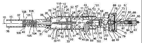
Fig. 1 is a perspective view of a device according to the invention for
vaporising vaporisable matter to produce an aerosol thereof,
Fig. 2 is a front elevational view of the device of Fig. 1 with a portion of
the
device removed,
Fig. 3 is an enlarged front elevational view of a portion of the device of
Fig. 1,
Fig. 4 is a transverse cross-sectional underneath plan view of the portion of
Fig. 3 on the line IV-IV of Fig. 3,
Fig. 5 is a perspective view of a detail of the device of Fig. 1,
Fig. 6 is a perspective view of another detail of the device of Fig. 1,
Fig. 7 is a transverse cross-sectional top plan view of a portion of the
device
of Fig. 1 on the line VII-VII of Fig. 3,
Fig. 8 is a perspective view of another detail of the device of Fig. 1,
Fig. 9 is an end elevational view of the detail of Fig. 8 of the device of
Fig. 1,
Fig. 10 is a transverse cross-sectional front elevational view of another
detail
of the device of Fig. 1,
Fig. 11 is an end view of the detail of Fig. 10 of the device of Fig. 1,
Fig. 12 is an end view of another detail of the device of Fig. 1,
Fig. 13 is a perspective view of a portion of the device of Fig. 1,
CA 02595831 2007-07-24
WO 2006/082571
PCT/1E2006/000006
18
Fig. 14 is an elevational view of the portion of Fig. 13 of the device of Fig.
1,
Fig. 15 is a transverse cross-sectional underneath plan view of the portion of
Fig. 14 on the line XV-XV of Fig. 14,
Fig. 16 is a perspective view of another portion of the device of Fig. 1,
Fig. 17 is an elevational view of the portion of Fig. 16 of the device of Fig.
1,
Fig. 18 is a transverse cross-sectional underneath plan view of the portion of
Fig. 17 on the line XVIII-XVIII of Fig. 17,
Fig. 19 illustrates waveforms representative of measured temperatures of the
device of Fig. 1 operating under one condition,
Fig. 20 illustrates waveforms representative of measured temperatures of the
device of Fig. 1 operating under a different condition to that of Fig. 19,
Fig. 21 is a front elevational view of a portion of a device according to
another
embodiment of the invention for vaporising vaporisable matter to produce an
aerosol thereof,
Fig. 22 is a transverse cross-sectional plan view of the portion of the device
of Fig. 21 on the line XXII-)0(11 of Fig. 21,
Fig. 23 is an exploded perspective view of the device of Fig. 21,
Fig. 24 is a view similar to Fig. 4 of a portion of a device according to
another
embodiment of the invention for vaporising vaporisable matter to produce an
aerosol thereof, and
Fig. 25 is a perspective view of a detail of a device according to a further
CA 02595831 2007-07-24
WO 2006/082571
PCT/IE2006/000006
19
embodiment of the invention for vaporising vaporisable matter to produce an
aerosol thereof.
Referring to the drawings and initially to Figs. 1 to 20, there is illustrated
a device
according to the invention, indicated generally by the reference numeral 1,
for
vaporising vaporisable matter, in this case tobacco, to produce an inhaleable
aerosol
from vaporisable constituents of the tobacco. The device 1 is encased in a two-
part
casing 3 formed by first and second casing shells 4 and 5 of injection moulded
plastics material, which are secured together by screws (not shown). An
elongated
main housing 9 of circular transverse cross-section is located within the
casing 3 and
defines a longitudinally extending main central axis 10. The main housing 9 is
of
heat conductive material, which in this embodiment of the invention is of
aluminium,
and comprises two parts, namely, an outer part 11 and an inner part 12. The
outer
part 11 of the main housing 9 forms a cylindrical outer side wall 14, while
the inner
part 12 of the main housing 9 forms a cylindrical inner side wall 15. The
inner and
outer side walls 15 and 14 of the main housing 9 form a combustion chamber
housing 17 within which a combustion chamber 18 is formed. A heating means, in
this embodiment of the invention a gas catalytic combustion element 19, which
is
described in more detail below, is located within the combustion chamber 18
for
converting fuel gas to heat for heating the combustion chamber housing 17 and
in
turn the main housing 9.
The outer part 11 of the main housing 9 also forms a cylindrical socket
portion 20 of
a vaporising chamber housing 21 which co-operates with a releasable plug
portion
22 of the vaporising chamber housing 21 to form a vaporising chamber 24 within
which the tobacco is located for vaporising the vaporisable constituents
thereof to
produce the aerosol. The plug portion 22 is also of a heat conductive
material,
which is also aluminium. The outer side wall 14 of the outer part 11 of the
main
housing 9 forms a primary side wall 25 of the socket portion 20, which with a
primary
partition wall 28 extending transversely of the outer side wall 14 forms a
primary
hollow interior region 29 of the socket portion 20 within which the plug
portion 22 of
the vaporising chamber housing 21 is releasably engageable. The plug portion
22
CA 02595831 2007-07-24
WO 2006/082571
PCT/1E2006/000006
comprises a cylindrical secondary side wall 30 and an end cap 31 extending
transversely of the secondary side wall 30, which with the secondary side wall
30
defines a secondary hollow interior region 32 within which the tobacco is
placed.
The secondary side wall 30 defines an open mouth 33 to the secondary hollow
5 interior region 32, while the primary side wall 25 of the socket portion
20 defines an
open mouth 34 to the primary hollow interior region 29 for receiving the plug
portion
22, so that when the plug portion 22 is engaged in the primary hollow interior
region
29, the secondary hollow interior region 32 communicates with the primary
hollow
interior region 29 through the open mouth 33 to form with the primary hollow
interior
10 region 29 the vaporising chamber 24. A sealing means comprising an 0-
ring seal 39
extends around the secondary side wall 30 adjacent an annular shoulder 41 for
abutting the primary side wall 25 adjacent the open mouth 34 to the primary
hollow
interior region 29 for sealing the vaporising chamber 24, when the plug
portion 22 is
fully engaged in the socket portion 20.
An aerosol accommodating outlet port 35 in the end cap 31 accommodates the
aerosol from the vaporising chamber 24. A downstream disc 36 of metal mesh
material located in the secondary hollow interior region 32 of the plug
portion 22
adjacent the aerosol accommodating outlet port 35 retains the tobacco in the
vaporising chamber 24. An aerosol accommodating tube 37 of plastics material
extending from the aerosol accommodating outlet port 35 terminates in a
mouthpiece 38 for facilitating inhaling of the aerosol from the vaporising
chamber 24.
A heat sink means comprising a heat sink member 40 of heat conductive
material,
namely, aluminium is located in the aerosol accommodating tube 37 for cooling
the
aerosol as it is drawn through the aerosol accommodating tube 37, and for
condensing tarry and other toxic vaporised constituents of the tobacco in the
aerosol
being drawn through the aerosol accommodating tube 37, as will be described in
more detail below.
An exhaust gas chamber 42 is formed in the main housing 9 by the outer side
wall
14 of the outer part 11 of the main housing 9 between the combustion chamber
18
CA 02595831 2007-07-24
WO 2006/082571
PCT/IE2006/000006
21
and the vaporising chamber 24. The exhaust gas chamber 42 communicates with
the combustion chamber 18 through a metal gauze membrane 44 which extends
transversely of the outer side wall 14 at the downstream end of the combustion
chamber 18. A plurality of exhaust gas ports 45 extending through the outer
side
wall 14 which forms the exhaust gas chamber 42 accommodate exhaust gases from
the exhaust gas chamber 42. The primary partition wall 28 forms a heat
exchange
means for facilitating the transfer of heat from the exhaust gases in the
exhaust gas
chamber 42 into the vaporising chamber 24, and also for preventing entry of
exhaust
gases from the exhaust gas chamber 42 into the vaporising chamber 24.
A heat transfer means, namely, an elongated heat transfer member 46 sealably
secured in a bore 47 through the primary partition wall 28 extends into the
vaporising
chamber 24 for transferring heat into tobacco in the vaporising chamber 24.
The
heat transfer member 46 is of heat conductive material, namely, aluminium, and
extends at 48 into the exhaust gas chamber 42 for facilitating efficient
transfer of
heat from the exhaust gases in the exhaust gas chamber 42 into the vaporising
chamber 24. The heat transfer member 46 tapers towards its distal end and
terminates in a point 49 for puncturing a sachet of tobacco if the tobacco is
placed in
a sachet in the secondary hollow interior region 32 of the plug portion 22, as
the plug
portion 22 is being engaged in the socket portion 20.
A secondary partition wall 50 extends transvers,ely across the primary hollow
interior
region 29 parallel to and spaced apart from the primary partition wall 28 for
defining
with the primary partition wall 28 and the primary side wall 25 an air inlet
chamber
51. The secondary partition wall 50 is of perforated aluminium with a
plurality of air
accommodating holes 52 extending therethrough for accommodating air from the
air
inlet chamber 51 to the vaporising chamber 24 as the aerosol is being drawn
from
the vaporising chamber 24. A primary air inlet port 53 accommodates air into
the air
inlet chamber 51 to be drawn into the vaporising chamber 24.
A rechargeable fuel gas reservoir 55 located in the casing 3 stores fuel gas
in liquid
form, which in this embodiment of the invention is a butane based gas in
liquid form.
CA 02595831 2007-07-24
WO 2006/082571 PCT/1E2006/000006 _
_
22
Fuel gas is delivered from the fuel gas reservoir 55 through a pressure
regulator 56
located in an outlet 57 from the reservoir 55 for adjusting the pressure of
the fuel gas
as it exits the fuel gas reservoir 55. A button operated on/off valve 62 also
adjacent
the outlet 57 from the reservoir 55 switches on and off the fuel gas from the
fuel gas
reservoir 55. A fuel gas pipe 59 couples the on/off valve 62 to a temperature
responsive safety isolating valve 60, which is provided for isolating the fuel
gas
supply from the fuel gas reservoir 55 to the combustion chamber 18 in the
event of
the temperature of the main housing 9 exceeding a predetermined upper maximum
safe working temperature. The temperature responsive safety isolating valve 60
is
described in detail below.
A temperature responsive control valve 61, which is described below, is
located
downstream of the safety isolating valve 60 for controlling the supply of fuel
gas to
the combustion chamber 18 for maintaining the temperature within the
vaporising
chamber 24 at a predetermined temperature, which in this embodiment of the
invention is in the range of 130 C to 250 C for vaporising desirable
vaporisable
constituents from the tobacco to produce the aerosol, and for minimising
vaporisation of undesirable constituents from the tobacco. An outlet nozzle 63
from
the temperature responsive control valve 61 delivers fuel gas from the control
valve
61 into a mixing means, namely, a venturi mixer 64 where the fuel gas is mixed
with
air. The venturi mixer 64 is formed in the inner part 12 of the main housing
9, and air
ports 68 in the inner part of the main housing 9 accommodate air into the
venturi
mixer 64. A diffuser comprising a diffuser plate 65 having a plurality of
bores 66
extending therethrough located intermediate the venturi mixer 64 and the
combustion chamber 18 distributes fuel gas/air mixture from the venturi mixer
64 into
the combustion chamber 18, and in turn to the gas catalytic combustion element
19,
see Fig. 12.
The gas catalytic combustion element 19 is located in the combustion chamber
18 to
define with the combustion chamber 18 a flame cavity 67 within which the fuel
gas/air mixture is initially burnt in a flame for raising the temperature of
the gas
catalytic combustion element 19 to its ignition temperature, so that as the
gas
CA 02595831 2012-10-26
23
catalytic combustion element 19 reaches its ignition temperature it commences
to convert
fuel gas to heat, thus starving the flame of fuel gas/air mixture, which is
then extinguished.
An electrode 69 extends through an electrically insulating mounting 70 into
the flame cavity
67 and co-operates with the inner side wall 15 of the inner part 12 of the
main housing 9 for
causing a spark to arc between the electrode 69 and the inner side wall 15 for
igniting the
fuel gas initially to burn in a flame. The insulating mounting 70 is located
in a bore 58
through the inner part 12 of the main housing 9, and a slot 43 in the outer
part 11 of the main
housing 9 accommodates the insulating mounting 70 therethrough. A piezo-
electric ignition
mechanism 71 located within the casing 3 is coupled to the electrode 69 for
producing a
voltage to cause the spark to arc between the electrode 69 and the inner side
wall 15 of the
main housing 9. A plunger 72 of the piezo-electric ignition mechanism 71
extends through
the casing 3 for facilitating activation of the piezo-electric ignition
mechanism 71 for causing
the spark to arc between the electrode 69 and the inner side wall 15 of the
main housing 9.
The main housing 9 is earthed through an earth strap (not shown) to the piezo-
electric
ignition mechanism 71.
Turning now to the temperature responsive control valve 61, and referring in
particular to Fig.
7, the temperature responsive control valve 61 is substantially similar to the
temperature
responsive control valve disclosed in PCT Published Application Specification
No.
WO 02/48591. The temperature responsive control valve 61 comprises a two-part
valve
housing 73 formed by an outer part 74 and an inner part 75 in sealable
engagement with the
outer part 74, and forming with the outer part 74 a valve chamber 76. The
outer and inner
parts 74 and 75 of the valve housing 73 are of heat conductive material,
namely aluminium,
and are in heat conducting engagement with the inner part 12 of the main
housing 9. A
valve inlet 77 in the outer part 74 of the valve housing 73 accommodates fuel
gas from the
safety isolating valve 60 into the valve chamber 76 and defines a valve seat
78. A bi-metal
valving disc 79 is located in the valve chamber 76 and carries a valving
CA 02595831 2007-07-24
WO 2006/082571
PCT/1E2006/000006
24
element 80 which is engageable with the valve seat 78 for controlling the flow
of fuel
gas into the valve chamber 76. An outlet nozzle 81 located in the inner part
75
delivers fuel gas from the valve chamber 76 into the venturi mixer 64. The bi-
metal
valving disc 79 is a temperature responsive bi-metal disc of the type, which
on being
subjected to a predetermined temperature as the temperature is rising
transitions
from a first dished configuration to a second dished configuration which is a
mirror
image of the first dished configuration, and on being subjected to the same or
a
slightly lower predetermined temperature as the temperature is falling,
transitions
from the second configuration to the first configuration. However, in order to
control
the flow of fuel gas into the valve chamber 76 with an analogue type
controlling
action, the bi-metal valving disc 79 is constrained by a shoulder 107 of the
inner part
75 of the valve housing 73 within the valve chamber 76 to prevent
transitioning of the
valving disc 79 between the first and second configurations. The operation of
this
type of temperature responsive control valve is described in PCT Published
Application Specification No. WO 02/48591. A filter 82 located in the inner
part 75 of
the valve housing 73 between the outlet nozzle 81 and an outlet port 103 from
the
valve chamber 76 filters the fuel gas delivered to the outlet nozzle 81.
As discussed above, the inner part 75 and the outer part 74 of the valve
housing 73
are in heat conducting engagement with the inner part 12 of the main housing
9, and
accordingly the valve housing 73 and in turn the valve chamber 76 and the bi-
metal
valving disc 79 are maintained at a temperature which is indicative of the
temperature of the main housing 9, and since the vaporising chamber housing 21
is
formed by part of the main housing 9, the temperature of the valve housing 73
and
the bi-metal valving disc 79 is indicative of the temperature of the
vaporising
chamber housing 21 and in turn the temperature within the vaporising chamber
24.
Thus, the bi-metal valving disc 79 is responsive to the temperature within the
vaporising chamber 24. The thermal mass of the main housing 9, the plug
portion
22 of the vaporising chamber housing 21 as well as the valve housing 73 and a
body
member 83 of the temperature responsive safety isolating valve 60 are
thermally
balanced so that the temperature responsive control valve 61 operates to
control the
supply of fuel gas to the combustion chamber 18 to maintain the temperature
within
4 CA 02595831 2012-10-26
the vaporising chamber 24 within the temperature range of 130 C to 250 C. The
temperature at which the main housing 9 is maintained by the temperature
responsive
control valve 61 is described below with reference to Figs. 19 and 20.
5 The temperature responsive safety isolating valve 60 is substantially
similar to a safety cut-
out mechanism disclosed in PCT Published Application Specification No. WO
02/48591.
The body member 83 of the temperature responsive safety isolating valve 60 is
of heat
conducting material, namely, aluminium, and extends from and is in heat
conducting
10 engagement with the outer part 74 of the valve housing 73 of the
temperature responsive
control valve 61. A bore 84 extending through the body member 83 communicates
with the
valve inlet 77 of the temperature responsive control valve 61. An inlet port
85 is coupled to
the fuel gas pipe 59 and delivers fuel gas from the fuel gas reservoir 55 into
the bore 84. A
slug 86 of plastics material impregnated with fibre glass material is located
in the bore 84 and
15 is a loose fit therein for permitting the flow of fuel gas through the
bore 84 past the slug 86
from the inlet port 85 to the valve inlet 77 of the temperature responsive
control valve 61. A
porous sintered bronze filter 87 is located in the bore 84 downstream of the
slug 86 for
filtering and accommodating fuel gas therethrough. A compression spring 88
acting between
the inlet port 85 and a perforated disc 89 urges the slug 86 towards the
filter 87. The disc 89
20 is perforated for accommodating fuel gas therethrough. Longitudinal
channels 90 and radial
channels 91 extending in the slug 86 accommodate fuel gas past the slug 86 to
the filter 87
and in turn to the valve inlet 77 of the temperature responsive control valve
61. The melt
temperature of the plastics material of the slug 86 is such that when the
temperature of the
main housing 9 reaches a predetermined unsafe working temperature, the
plastics material
25 of the slug 86 melts, and the action of the compression spring 88
against the disc 89 urges
the melting plastics material towards and into the sintered filter 87, thereby
blocking the
sintered filter 87 and preventing flow of fuel gas therethrough, thus
isolating the temperature
responsive control valve 61 and in turn the combustion chamber 18 from the
fuel gas
reservoir 55.
CA 02595831 2007-07-24
WO 2006/082571
PCT/1E2006/000006
26
Turning now to the gas catalytic combustion element 19 and referring in
particular to
Figs. 8 and 9, in this embodiment of the invention the gas catalytic
combustion
element comprises a perforated sheet metal carrier 92 coated with a suitable
catalytic precious metal material. The catalytic coated carrier 92 is formed
into a
hollow cylinder 93 defining a fuel gas accommodating bore 94 extending
thereth rough. A tab portion 95 is formed from the catalytic coated carrier 92
and is
bent inwardly to extend into the gas accommodating bore 94. A thermal mass 96
comprising a screw 97 and a nut 98 is secured to the tab portion 95 for
maintaining
the tab portion 95 at or above the ignition temperature of the gas catalytic
combustion element 19 during periods of fuel gas interruption to the gas
catalytic
combustion element 19 resulting from control of the supply of fuel gas to the
combustion chamber 18 by the temperature responsive control valve 61. Thus, in
this way, when the supply of fuel gas is reinstated by the temperature
responsive
control valve 61, the tab portion 95, which has been maintained at or above
the
ignition temperature, again commences conversion of the fuel gas to heat by
catalytic reaction, thereby progressively and rapidly raising the temperature
of the
remainder of the gas catalytic combustion element 19 to its ignition
temperature.
The screw 97 of the thermal mass 96 comprises a head 99 and a threaded shank
100 which extends through the tab portion 95. The tab portion 95 is tightly
clamped
between the nut 98 and the head 99 of the screw 97, thereby maintaining good
heat
conducting engagement between the thermal mass 96 and the tab portion 95. The
thermal mass 96 is located within the gas accommodating bore 94 of the
cylindrical
carrier 92 for minimising heat loss from the thermal mass 96 to the main
housing 9.
The mass of the thermal mass 96 is sized to be of sufficient mass for storing
sufficient heat during periods while the gas catalytic combustion element 19
is
converting fuel gas to heat so that the temperature of the thermal mass 96
remains
at or above the ignition temperature of the gas catalytic combustion element
for the
duration of the longest period of fuel gas interruption to the combustion
chamber 18
by the temperature responsive control valve 61. Thereby, the thermal mass 96
co-
operates with the temperature responsive control valve 61 for preventing the
tab
portion 95 of the gas catalytic combustion element falling below its ignition
CA 02595831 2007-07-24
WO 2006/082571
PCT/1E2006/000006
27
temperature while the device 1 is operating to produce the aerosol from the
tobacco
in the vaporising chamber 24. Thus, once the gas catalytic combustion element
19
has been raised to its ignition temperature initially by flame combustion, the
gas
catalytic combustion element 19 continues to operate to convert fuel gas to
heat
without the need to re-ignite the gas catalytic combustion element 19 by flame
combustion after each period of interruption of fuel gas to the combustion
chamber
resulting from the operation of the temperature responsive control valve 61,
since
the thermal mass 96 maintains the tab portion 95 of the gas catalytic
combustion
element at or above its ignition temperature during periods of fuel gas
interruption to
the combustion chamber 18. It is the fact that the thermal mass 96 co-operates
in
this way with the temperature responsive control valve 61 which permits the
main
housing 9 to be maintained at a temperature in the range of 130 C to 250 C,
and in
turn the vaporising chamber 24 to be maintained at a temperature in the range
of
130 C to 250 C, while the gas catalytic combustion element 19 is converting
fuel gas
to heat at an operating temperature in the order of 800 C to 900 C, since the
gas
catalytic combustion element 19 can be operated in the non-converting state
for
periods of relatively long duration.
A first inspection port 101 formed by bores 114 and 115 through the outer and
inner
side walls 14 and 15, respectively, of the main housing 9 facilitates
inspection of the
flame cavity 67 for inspecting a flame during initial flame combustion of the
fuel
gas/air mixture in the combustion chamber 18. A second inspection port 102
formed
by bores 116 and 117 through the outer side wall 14 and the inner side wall
15,
respectively, of the main housing 9 to the combustion chamber 18 adjacent the
gas
catalytic combustion element 19 facilitates inspection of the gas catalytic
combustion
element 19.
Returning now to the heat sink member 40 and referring in particular to Figs.
10 and
11, the heat sink member 40 is of heat conductive material machined from a
single
piece of aluminium and comprises an elongated solid core member 104. A
plurality
of heat exchange fins 105 spaced apart longitudinally along the core member
104
extend circumferentially completely around the core member 104 and engage an
CA 02595831 2007-07-24
WO 2006/082571
PCT/1E2006/000006
28
inner surface 106 of the aerosol accommodating tube 37, see Fig. 4. The heat
exchange fins 105 define with the core member 104 and the inner surface 106 of
the
aerosol accommodating tube 37 a plurality of galleries 108. Longitudinally
extending
slots 109 provided at the periphery of the heat exchange fins 105 communicate
adjacent galleries 108 for facilitating the passage of the aerosol through the
aerosol
accommodating tube 37 past the heat sink member 40. In order to maximise the
contact of the aerosol with the heat sink member 40, the slots 109 are spaced
apart
around the heat exchange fins 105, and the slots 109 of each heat exchange fin
105
are located at 180' around the periphery of the heat exchange fin 105, and are
misaligned with the slots 109 of the two adjacent heat exchange fins 105 by 90
.
Accordingly, the aerosol is drawn through a tortuous path defined by the
galleries
108 and the slots 109 of the heat sink member 40 for cooling thereof and for
facilitating condensing of tar and other undesirable vaporised constituents.
An adjustable secondary air inlet port 110 comprising a pair of bores 112 and
113
radially extending through the primary side wall 25 and the secondary side
wall 30,
respectively, of the vaporising chamber housing 21 are located downstream of
the
primary air inlet port 53 for accommodating additional air into the vaporising
chamber
24. The bores 112 and 113 are alignable when the plug portion 22 is fully
engaged
in the socket portion 20, and are aligned with each other by rotating the plug
portion
22 in the socket portion 20. Additionally, when the bores 112 and 113 are
aligned,
the area of the orifice defined by the bores 112 and 113 is adjustable by
rotating the
plug portion 22 relative to the socket portion 20 to act as an adjusting means
for
varying the amount of air drawn through the secondary air inlet port 110. The
secondary air inlet port 110 is closed by rotating the plug portion 22
relative to the
socket portion 20 so that the respective bores 112 and 113 are overlaid with
the
primary and secondary side walls 25 and 30.
In this embodiment of the invention the entire main housing 9, the plug
portion 22,
the aerosol accommodating tube 37 and the mouthpiece 38, as well as the
temperature responsive control valve 61 and the temperature responsive safety
isolating valve 60 are all axially aligned and define respective central axes,
all of
CA 02595831 2007-07-24
WO 2006/082571
PCT/1E2006/000006
29
which coincide with the main central axis 10 defined by the main housing 9.
The
body member 83 of the temperature responsive safety isolating valve 60 and the
valve housing 73 of the temperature responsive control valve 61 are of
cylindrical
construction and the gas accommodating tube 37 is of circular transverse cross-
section.
In use, with the plug portion 22 disengaged from the socket portion 20 of the
vaporising chamber housing 21, tobacco to be vaporised is placed in the
secondary
hollow interior region 32 of the plug portion 22. The plug portion 22 is then
re-
engaged in the socket portion to form with the primary hollow interior region
29 the
vaporising chamber 24. The tobacco may be placed in the secondary hollow
interior
region 32 of the plug portion 22 in loose form or in a sachet. If placed in
the
secondary hollow interior region 32 in a sachet, as the plug portion 22 is
being
engaged in the socket portion 20 and urged tightly into the primary hollow
interior
region 29, the heat transfer member 46 punctures the sachet, for permitting
the
release of the aerosol of the vaporised constituents of the tobacco when the
tobacco
has been heated in the vaporising chamber 24.
With the tobacco located in the vaporising chamber 24, the device 1 is ready
for use.
The button operated on/off valve 62 is activated for supplying fuel gas from
the fuel
gas reservoir 55 through the temperature responsive safety isolating valve 60
and
the temperature responsive control valve 61 to the venturi mixer 64 where the
fuel
gas is mixed with air, and delivered through the diffuser 65 into the
combustion
chamber 18. The plunger 72 of the piezo-electric ignition mechanism 71 is
activated
for delivering a voltage to the electrode 69 to cause a spark to arc between
the
electrode 69 and the inner side wall 15 of the main housing 9. The fuel
gas/air
mixture in the combustion chamber 18 commences to burn in a flame in the flame
cavity 67, thereby raising a downstream portion of the gas catalytic
combustion
element 19 to its ignition temperature. On reaching its ignition temperature,
the gas
catalytic combustion element commences to convert fuel gas to heat by
catalytic
reaction, thus progressively and rapidly raising the temperature of the
remainder of
the gas catalytic combustion element 19 to its ignition temperature, until the
entire
CA 02595831 2007-07-24
WO 2006/082571
PCT/1E2006/000006
gas catalytic combustion element 19 is converting fuel gas to heat. At that
stage, the
flame is starved of fuel gas and is extinguished.
The gas catalytic combustion element 19 converts fuel gas to heat at an
operating
5 temperature of between 800 C and 900 C. The temperature of the main
housing 9
is rapidly raised to its operating temperature in the range of 130 C to 250 C
by heat
radiated from the gas catalytic combustion element 19. Heat conducted through
the
main housing 9 and through the heat transfer member 46 raises the temperature
within the vaporising chamber 24, and in turn the temperature of the tobacco
to a
10 temperature in the range of 130 C to 250 C to produce the aerosol.
Simultaneously,
heat is conducted through the main housing 9 to the valve housing 73 of the
temperature responsive control valve 61 and to the body member 83 of the
temperature responsive safety isolating valve 60. Heat is transferred from the
valve
housing 73 into the bi-metal valving disc 79 of the temperature responsive
control
15 valve 61, which operates to control the supply of fuel gas to the
combustion chamber
18 to maintain the temperature of the main housing 9 so that the temperature
within
the vaporising chamber 24 is between 130 C and 250 C.
On the temperature in the vaporising chamber 24 reaching a temperature in the
20 range of 130 C to 250 C, desirable vaporisable constituents, for
example, nicotine
and other desirable constituents, are vaporised from the tobacco to produce
the
aerosol. Some tar and other undesirable components are also vaporised from the
tobacco, however, by maintaining the temperature within the vaporising chamber
24
within the temperature range of 130 C to 250 C, the amount of tar and other
25 undesirable constituents which are vaporised from the tobacco is
minimised.
A user places the mouthpiece 38 in his or her mouth and draws on the
mouthpiece
38, thus drawing air through the primary air inlet 53 through the vaporising
chamber
24. The aerosol from the vaporising chamber 24 is entrained in the air, and
drawn
30 along with the air through the heat sink member 40. The heat sink member
40 cools
the vaporised constituents and condenses tar and other undesirable vaporised
constituents from the tobacco onto the heat exchange fins 105. The user then
CA 02595831 2007-07-24
WO 2006/082571
PCT/1E2006/000006
31
inhales the mixture of air and aerosol. If it is desired to increase or
decrease the
amount of air being draw into the vaporising chamber 24, the plug portion 22
is
rotated relative to the socket portion 20 for either aligning or misaligning
the bores
112 and 113 of the secondary air inlet port 110, or for closing off the
secondary air
inlet port 110 entirely.
The device continues to operate until the on/off valve 62 has been deactivated
for
isolating the fuel gas from the fuel gas reservoir to the combustion chamber
18.
During operation the temperature responsive control valve 61 operates to
maintain
the temperature within the vaporising chamber 24 within the temperature range
130 C to 250 C by varying the rate of supply of fuel gas to the combustion
chamber
18 with an analogue type action, and also by periodically interrupting the
supply of
fuel gas to the combustion chamber 18 where necessary. During periods of
interruption of fuel gas to the combustion chamber 18 resulting from
temperature
control by the temperature responsive control valve 61, the thermal mass 96
maintains a portion of Ow tab portion 95 of the gas catalytic combustion
element 19
adjacent the thermal mass 96 at or above the ignition temperature of the gas
catalytic combustion element 19, so that when the supply of fuel gas is
reinstated,
the gas catalytic combustion element 19 again commences to convert the fuel
gas/air mixture to heat.
Referring now to Figs. 19 and 20, there is illustrated waveforms
representative of
operating temperatures of the device 1 of Figs. 1 to 18 when the device 1 is
operating under two different conditions. In order to operate the device 1 at
a
desired temperature within the range of 130 C to 250 C, the temperature
responsive
control valve 61 must be selected to operate the device at the desired
temperature
within the range of 130 C to 250 C. To produce the temperature results of Fig.
19,
the temperature responsive control valve 61 was selected to operate the device
1
with the temperature in the vaporising chamber 24 maintained at approximately
164 C. To produce the temperature results of Fig. 20, the temperature
responsive
control valve 61 was selected to operate the device 1 with the temperature in
the
CA 02595831 2007-07-24
WO 2006/082571
PCT/1E2006/000006
32
vaporising chamber 24 maintained at approximately 220 C.
In Figs. 19 and 20 temperature is plotted on the Y-axis in C, and time is
plotted on
the X-axis in seconds. The waveform A in both Figs. 19 and 20 is
representative of
the temperature of the main housing 9 of the device 1 adjacent the combustion
chamber 18. The waveform B in both Figs. 19 and 20 is representative of the
temperature of the heat transfer member 46 within the vaporising chamber 24 of
the
device 1, and thus this temperature of the heat transfer member 46 is a
relatively
accurate representation of the value of the temperature within the vaporising
chamber 24. The waveform C in both Figs. 19 and 20 is representative of the
temperature of the exhaust gases exiting through the exhaust gas ports 45 from
the
exhaust gas chamber 42 of the device 1.
As can be seen from Fig. 19, when the temperature responsive control valve 61
is
selected to operate the device 1 with the temperature in the vaporising
chamber at
approximately 164 C, the temperature of the heat transfer member 46, after an
initial
excursion to 190 C after start-up, settles at a steady state temperature,
which
fluctuates between 160 C approximately and 168 C approximately. Accordingly,
during steady state operation of the device 1, the temperature in the
vaporising
chamber 24 is maintained at approximately 164 C 4 C. From start-up the
temperature of the heat transfer member 46 rises to approximately 190 C before
settling at the steady state temperature of 164 C 4 C. The temperature of
the
main housing 9 rises to approximately 175 C, before settling at a steady state
operating temperature of approximately 166 C 4 C. The initial heating up of
the
device 1 from start-up until steady state operating conditions have been
reached
takes approximately 120 seconds, in other words, approximately two minutes.
The
exhaust gas temperature exiting the exhaust gas ports 45 during the initial
period
after start-up rises to approximately 155 C, and then settles to a steady
state
temperature of approximately 125 C 15 C.
As can be seen from Fig. 20, when the temperature responsive control valve 61
is
selected to operate the device with the vaporising chamber 24 at a temperature
of
CA 02595831 2007-07-24
WO 2006/082571
PCT/1E2006/000006
33
approximately 220 C. The device 1 from start-up takes approximately 120
seconds
to reach steady state operating conditions. Initially the temperature of the
main
housing 9 reaches a temperature of approximately 230 C and then settles back
to a
steady state operating temperature of approximately 225 C 3 C. The
temperature
of the heat transfer member 46 initially rises to a temperature of
approximately
240 C before settling back to a steady state operating temperature of
approximately
220 C 3 C. Thus, the temperature within the vaporising chamber 24 is
maintained
at a steady state operating temperature of approximately 220 C 3 C. The
temperature of the exhaust gas exiting through the exhaust gas ports 45
initially
reaches a temperature of approximately 215 C, falling back to a temperature of
approximately 120 C before settling at an average steady state temperature of
approximately 175 C 10 C.
Accordingly, by appropriately selecting the temperature responsive control
valve 61,
the device 1 can be operated at any desired temperature. While, in general,
the
temperature responsive control valve will be selected to operate the device 1
at
steady state operating temperatures in the vaporising chamber 24 at
temperatures
within the range of 130 C to 250 C, it is envisaged, in certain cases, that
the
temperature responsive control valve may be selected to control the device at
higher
or lower temperatures, and the temperature at which the temperature responsive
control valve is selected to control the device will be determined by the
matter being
vaporised in the vaporising chamber to form the aerosol. Indeed, it will be
appreciated that the temperature responsive control valve 61 may be selected
to
operate the device 1 at steady state operating temperatures in the vaporising
chamber 24 at temperatures considerably higher than 250 C, for example, at
temperatures of up to 400 C, and even higher, depending on the matter to be
vaporised to form the aerosol.
It will also be understood that the thermal mass 96 will be selected for
maintaining
the tab portion 95 of the gas catalytic combustion element 19 at or above the
ignition
temperature of the gas catalytic combustion element for periods during
temperature
interruption resulting from control of the temperature of the device by the
CA 02595831 2007-07-24
WO 2006/082571
PCT/1E2006/000006
34
temperature responsive control valve 61. Thus, the thermal mass will be
matched
with and will co-operate with the temperature responsive control valve.
Indeed, as
can be seen from Figs. 19 and 20, when the temperature responsive control
valve
61 is selected to operate the device with the temperature in the vaporising
chamber
24 at the lower steady state operating temperature of 164 C, the periods
during
which the fuel gas is interrupted to the gas catalytic combustion element 19
are
longer than the periods during which the fuel gas is interrupted to the gas
catalytic
combustion element 19 when the temperature responsive control valve is
selected to
operate the device with a steady state operating temperature in the vaporising
chamber 24 of approximately 220 C. The durations of the periods during which
the
= fuel gas is interrupted to the combustion chamber 18 can be determined
from the
time periods during which the temperatures of the waveforms A, B and C fall
from
their peak value to their minimum value before commencing to rise. From Fig.
19 it
can be seen that the average duration of the periods during which the fuel gas
is
interrupted to the gas catalytic combustion element 19 when the device is
operating
at a steady state operating temperature in the vaporising chamber 24 of
approximately 164 C is approximately twelve seconds, while from Fig. 20 the
average duration of the periods of fuel gas interruption to the gas catalytic
combustion element 19 when the device is operating at a steady state operating
temperature in the vaporising chamber 24 of approximately 220 C is
approximately
eight seconds.
Accordingly, the higher the steady state operating temperature in the
vaporising
chamber 24 at which the device us operated, the shorter will be the duration
of the
periods of fuel gas interruption to the gas catalytic combustion element 19
caused by
the temperature responsive control valve 61.
Referring now to Figs. 21 to 23, there is illustrated a portion of a device
according to
another embodiment of the invention, indicated generally by the reference
numeral
120, for vaporising tobacco to produce an inhaleable aerosol. The device 120
is
partly similar to the device 1 and similar components are identified by the
same
reference numerals. The main difference between the device 120 and the device
1
CA 02595831 2007-07-24
WO 2006/082571
PCT/1E2006/000006
is that the device 120 is electrically powered by a battery 121. The device
120
comprises a main housing 122 which is located within a casing (not shown)
which is
substantially similar to the casing 3. The battery 121 for powering the device
120 is
located in the casing 3 in a compartment in an area similar to the area in
which the
5 fuel gas reservoir 55 is located in the casing 3 of the device 1. The
main housing
122 is of heat conductive material, namely, aluminium, and forms the socket
portion
20 of the vaporising chamber housing 21.
A heating means for heating the tobacco in the vaporising chamber 24 to
produce
10 the aerosol comprises an electrically powered positive temperature
control resistive
heating element 125 which is located within and encased in the heat transfer
member 46 which extends into the vaporising chamber 24. The heat transfer
member 46 comprises a heat conductive shell 126 of aluminium, and the heating
element 125 is in heat conductive engagement with the heat conductive shell
126 of
15 the heat transfer member 46 for transferring heat to the tobacco. Heat
is also
transferred from the heating element 125 through the heat transfer member 46
into
the socket portion 20 of the vaporising chamber housing 21 for heating the
tobacco.
An on/off switch 128 is located in the casing (not shown) for switching on and
off
power to the heating element 125 from the battery 121. A temperature
responsive
20 switch 129 mounted on the primary side wall 25 is responsive to the
temperature of
the primary side wall 25, which in turn is indicative of the temperature
within the
vaporising chamber 24 for controlling the supply of power from the battery 121
to the
heating element 125 for maintaining the temperature within the vaporising
chamber
24 at a temperature in the range of 130 C to 250 C.
Otherwise, the device 120 is similar to the device 1, as is its use. Tobacco
is placed
in the secondary hollow interior region 32 of the plug portion 22 which is
engaged in
the socket portion 20 of the vaporising chamber housing 21 for forming the
vaporising chamber 24. The on/off switch 128 is operated for applying power
from
the battery 121 to the heating element 125 through the temperature responsive
switch 129 for powering the heating element 125, which in turn heats the
tobacco to
a temperature in the range of 130 C to 250 C. The temperature is maintained
within
CA 02595831 2007-07-24
WO 2006/082571
PCT/1E2006/000006
36
the range of 130 C to 250 C by the temperature responsive switch 129. When it
is
desired to deactivate the device 120, the on/off switch 128 is appropriately
operated.
Referring now to Fig. 24, there is illustrated a portion of a device according
to
another embodiment of the invention, indicated generally by the reference
numeral
130, for vaporising vaporisable matter to form an inhaleable aerosol. The
device
130 is substantially similar to the device 1, which is described with
reference to Figs.
1 to 20, and similar components are identified by the same reference numerals.
The
main difference between the device 130 and the device 1 is that in this
embodiment
of the invention the exhaust gas chamber 42 is substantially filled with a
heat
conductive gauze type material, which in this embodiment of the invention is a
knitted type metal fabric 131 of the type typically used in pot scrubs for
scouring
grease and other dirt from pots and pans. Such knitted type metal fabric
material will
be well known to those skilled in the art. The knitted metal fabric 131 is
randomly
folded and placed in the exhaust gas chamber 42. The portion 48 of the heat
transfer member 46 which extends into the exhaust gas chamber 42 extends into
the
knitted metal fabric 131 and is in heat conductive engagement therewith. The
knitted metal fabric 131 diffuses the exhaust gases from the combustion
chamber 18
throughout the exhaust gas chamber 42, thereby slowing down the flow of
exhaust
gases and also extracting heat therefrom. The heat extracted from the exhaust
gases by the knitted metal fabric 131 is transferred into the heat transfer
member 46
for transferring into the vaporising chamber 24. It has been found that the
inclusion
of the knitted metal fabric 131 in the exhaust gas chamber 42 reduces the
temperature of the exhaust gases exiting the exhaust gas ports 45, thereby
significantly improving the operating efficiency of the device 130 over and
above that
of the device 1, and indeed, it has been found that the temperature difference
between the temperature within the vaporising chamber 24 and the main housing
9
is also reduced.
Additionally, the device 130 comprises a valving means, namely, a non-return
valve
132 in the primary air inlet port 53 for permitting flow of air through the
primary inlet
port 53 into the vaporising chamber 24 when the aerosol is being drawn from
the
CA 02595831 2007-07-24
WO 2006/082571
PCT/1E2006/000006
37
vaporising chamber 24 through the mouthpiece 38, and for preventing reverse
flow
of aerosol through the primary air inlet port 53 from the vaporising chamber
24 when
the aerosol is not being drawn from the vaporising chamber 24 through the
mouthpiece 38. It has been found that in certain cases when the device is
operated
with the vaporising chamber 24 at a relatively high temperature, the aerosol
formed
in the vaporising chamber 24 permeates outwardly through the primary air inlet
port
53 during periods when the aerosol is not being drawn through the mouthpiece
38.
The provision of the non-return valve 32 in the primary air inlet port 53
prevents loss
of the aerosol from the vaporising chamber 24 through the primary air inlet
port 53.
Referring now to Fig. 25, there is illustrated a socket portion 140 of a
vaporising
chamber housing which is suitable for use with the device 1, the device 120
and 130.
In this embodiment of the invention the vaporising chamber housing is
substantially
similar to the vaporising chamber housing 21 described with reference to the
device
1, and similar components are identified by the same reference numerals. The
main
difference between the vaporising chamber housing of this embodiment of the
invention and the vaporising chamber housing 21 is that four parallel spaced
apart
heat transfer members 46 extend from the primary partition wall 28 into the
primary
hollow interior region 29 of the socket portion 20 for transferring heat to
tobacco in
the vaporising chamber 24. The heat transfer members 46 are similar to the
heat
transfer member 46 which extends into the vaporising chamber 24 of the device
1.
Otherwise, the socket portion 140 of the vaporising chamber housing is similar
to the
socket portion 20 of the vaporising chamber housing 21, and its use in
conjunction
with the plug portion 22 is similar for forming the vaporising chamber 24.
Where the
socket portion 140 is being used with the device 120, it is envisaged that a
heating
element 125, similar to that described with reference to the device 120 will
be
located in at least one of the heat transfer members 46, and preferably, in
each of
the heat transfer members 46.
While the heating means of the device 120 which has been described with
reference
to Figs. 21 to 23 has been described as being provided by a positive
temperature
control resistive heating element, any other suitable heating means may be
CA 02595831 2007-07-24
WO 2006/082571
PCT/1E2006/000006
38
provided, for example, the heating means may comprise a conventional resistive
heating element, an induction heating element or any other suitable heating
means.
It is also envisaged that the heating means may be provided in a portion of
the main
housing 122 which would extend axially rearwardly from the vaporising chamber
housing 21.
While the device 1 according to the invention described with reference to
Figs. 1 to
20 has been described as comprising heat transfer to the vaporising chamber by
both temperature conduction through the main housing and also by heat transfer
from the exhaust gases, it is envisaged in certain cases that heat transfer
from the
exhaust gases may be omitted.
While the device 130, which has been described with reference to Fig. 24, has
been
described as comprising a valving means for selectively controlling the flow
of air
through the primary air inlet port 53 in the form of a non-return valve, any
other
suitable valving means may be provided. Indeed, it is envisaged that the
valving
means may comprise a manually operated valving member, which would be
operated by a user, and which would normally be in the closed state, closing
the
primary air inlet port 53, and when a user wished to draw aerosol from the
vaporising
chamber 24, the valving member would be manually operated into the open state
by
the user for permitting air to enter the vaporising chamber 24 through the
primary air
inlet port 53. It is also envisaged that the device 1 according to the
invention, which
has been described with reference to Figs. 1 to 20, may also be provided with
a
suitable valving means for selectively controlling air through the primary air
inlet port
53, as could the device described with reference to Figs. 21 to 23. It is also
envisaged that the device 1 according to the invention, which is described
with
reference to Figs. 1 to 20, may also be provided with a heat conductive gauze
material located in the exhaust gas chamber. While the heat conductive gauze
material in the exhaust gas chamber described in the device 130 with reference
to
Fig. 24 has been described as being a knitted metal fabric of the type used in
pot
scrubs, any other suitable heat conductive material may be used. Indeed, in
certain
cases, it is envisaged that heat exchange fins may be provided extending from
the
CA 02595831 2007-07-24
WO 2006/082571
PCT/1E2006/000006
39
main housing into the exhaust gas chamber for transferring heat from the
exhaust
gases into the body member, and in turn to the vaporising chamber. Such heat
exchange fins could be arranged to form a tortuous passageway for the gas for
slowing the exhaust gases passing through the exhaust gas passageway.
While the thermal mass has been described as comprising a nut and screw, any
other suitable thermal mass may be used, for example, a rivet, and indeed, in
certain
cases, it is envisaged that a portion of the gas catalytic combustion element
may be
of mass sufficient for maintaining that portion of the gas catalytic
combustion
element at or above its ignition temperature for periods of fuel gas
interruption. For
example, if the gas catalytic combustion element were provided as a ceramic
gas
catalytic combustion element, the thermal mass of portions of the ceramic gas
catalytic combustion element may be sufficient for maintaining those portions
of the
gas catalytic combustion element at or above the ignition temperature of the
gas
catalytic combustion element for periods of fuel gas interruption.
While the device 1 according to the invention described with reference to
Figs. 1 to
has been described as comprising a secondary air inlet which is adjustable, it
is
envisaged that the secondary air inlet may be dispensed with. It is also
envisaged in
20 certain cases that the portion of the heat transfer member located
within the
vaporising chamber 24 and the air inlet chamber 51 may be provided with air
ducts
for accommodating air through the heat transfer member from the air inlet
chamber
51 to the vaporising chamber for heating the air in the heat transfer member
as it is
drawn from the air inlet chamber 51 to the vaporising chamber 24.
While the gas catalytic combustion element has been described as comprising a
perforated sheet metal carrier having a precious metal catalyst material
coated
thereon, any other suitable gas catalytic combustion element may be used, and
where the gas catalytic combustion element is provided with a sheet metal
carrier, it
is not essential that the sheet metal carrier be perforated. The gas catalytic
combustion element may also be provided with a mesh or gauze carrier
appropriately coated with a catalyst material. Needless to say, in certain
cases, it is
CA 02595831 2007-07-24
WO 2006/082571
PCT/1E2006/000006
envisaged that the gas catalytic combustion element may be a ceramic gas
catalytic
combustion element.
Additionally, it will be appreciated that while the vaporising chamber housing
21 has
5 been described as being formed as an integral part of the main housing 9
which also
forms the combustion chamber housing 17 of the device 1, it is envisaged, in
certain
cases, that the vaporising chamber housing and the combustion chamber housing
may be formed separately, but would be in heat conducting engagement with each
other either directly or through a heat conducting member.
While the devices according to the invention have been described with a
specific
type of temperature control valve for controlling the flow of fuel gas to the
combustion chamber, any other suitable temperature control valve may be used.
For example, in certain cases it is envisaged that a temperature control valve
comprising a self-latching relay of the type disclosed in PCT Published
Application
Specification No. WO 95/09712.
It is also envisaged that a filter may be provided in the aerosol
accommodating tube
either upstream or downstream of the heat sink member for filtering the
aerosol
being drawn therethrough. Such a filter may be of the type commonly used in
filter
tipped cigarettes, or any other suitable filter for filtering the aerosol from
the
vaporising chamber. Indeed, in certain cases, such a filter may be used
instead of
the heat sink member.
While the devices according to the invention have been described for producing
an
aerosol from tobacco, it is envisaged that the device may be adapted for
producing
an aerosol from any other vaporisable matter, such as any other vaporisable
herb or
plant matter, or a vaporisable medicinal compound or the like, and where the
device
is used for vaporising matter other than tobacco, the device will be adapted
for
operating with the steady state temperature in the vaporising chamber
maintained at
an appropriate temperature for the matter being vaporised.
CA 02595831 2007-07-24
WO 2006/082571
PCT/1E2006/000006
41
While the main housing, the temperature responsive control valve and the
temperature responsive isolating valve have been described as being of
aluminium
material, they may be of any other suitable heat conducting material, for
example,
brass, stainless steel, copper or the like.
While a particular type of heat sink means has been described for locating in
the
aerosol accommodating tube between the vaporising chamber and the mouthpiece,
any other suitable heat sink means could be provided. For example, in certain
cases, it is envisaged that the heat sink means may be provided in the form of
a
porous sintered filter, a gauze filter, which typically would be of metal
gauze material,
or any other suitable material suitable for cooling the aerosol to an
acceptable
mouth-feel temperature, and for condensing any steam or water vapour in the
aerosol.
While the heat transfer means have been described as comprising a heat
transfer
member extending into the vaporising chamber, any other suitable heat transfer
means may be provided, and while the heat transfer member or members have been
described as being of a particular material, the heat transfer member or
members
may be of any other suitable material. It is also envisaged that in the case
of
electrically powered devices, it is not essential that the heating means be
located in
the heat transfer member.
It will be appreciated that where the devices according to the invention are
provided
for vaporising vaporisable matter in tobacco, the tobacco may be placed in the
vaporising chamber in any suitable form, whether flake, granular, solid,
particulate,
or any desirable form.
Additionally, while the devices have been described as being operable within a
temperature range of 130 C to 250 C, it will be readily apparent to those
skilled in
the art that the devices according to the invention may be operated at any
desired
temperature, either below 130 C or above 250 C, and indeed, in certain cases,
the
devices may be operable at relatively high temperatures up to and above 400 C,
and
CA 02595831 2007-07-24
WO 2006/082571 PCT/1E2006/000006
42
even up to and above 500 C, and the operating temperatures will largely depend
on
the matter being vaporised.