Language selection

Search

Patent 2595997 Summary

Third-party information liability

Some of the information on this Web page has been provided by external sources. The Government of Canada is not responsible for the accuracy, reliability or currency of the information supplied by external sources. Users wishing to rely upon this information should consult directly with the source of the information. Content provided by external sources is not subject to official languages, privacy and accessibility requirements.

Claims and Abstract availability

Any discrepancies in the text and image of the Claims and Abstract are due to differing posting times. Text of the Claims and Abstract are posted:

  • At the time the application is open to public inspection;
  • At the time of issue of the patent (grant).
(12) Patent: (11) CA 2595997
(54) English Title: TERMINAL CONTACT FOR ELECTRIC CONDUCTORS
(54) French Title: CONTACT DE RACCORDEMENT POUR CONDUCTEURS ELECTRIQUES
Status: Deemed expired
Bibliographic Data
(51) International Patent Classification (IPC):
  • H01R 4/48 (2006.01)
  • H01R 13/46 (2006.01)
(72) Inventors :
  • FERDERER, ALBERT (Germany)
(73) Owners :
  • HARTING ELECTRIC GMBH & CO. KG (Germany)
(71) Applicants :
  • HARTING ELECTRIC GMBH & CO. KG (Germany)
(74) Agent: BORDEN LADNER GERVAIS LLP
(74) Associate agent:
(45) Issued: 2010-08-31
(22) Filed Date: 2007-08-02
(41) Open to Public Inspection: 2008-02-08
Examination requested: 2007-08-02
Availability of licence: N/A
(25) Language of filing: English

Patent Cooperation Treaty (PCT): No

(30) Application Priority Data:
Application No. Country/Territory Date
202006012106.4 Germany 2006-08-08

Abstracts

English Abstract


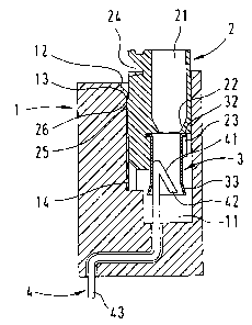
The invention proposes a terminal contact for electric conductors in an insu-
lating
housing (1) with electric contacts that are arranged in separate cham-bers
(11), wherein a clamping sleeve (3) is in axial alignment with and con-nected
to a slide element (2) that is also arranged in the chambers (11).

A single-wire or multi-wire electric conductor that is inserted into a through-
-bore
of the slide element and the clamping sleeve connected thereto is
pushed over a stationary, rigid and barb-shaped terminal region of the con-
ductor
rail while the slide element is axially moved along the chamber,
wherein the strands are clamped between the terminal region and the clamp-ing
sleeve.


French Abstract

Cette invention porte sur un contact de raccordement pour conducteurs électriques dans un boîtier isolant (1), dont les contacts électriques sont disposés dans des chambres distinctes (11). Un manchon de fixation (3) se trouve dans l'alignement de l'axe d'un élément à glissière (2) et y est relié; cet élément est également disposé dans les chambres (11). Un conducteur électrique unifilaire ou multifilaire inséré dans un orifice de l'élément à glissière, et le manchon de fixation qui y est relié, est poussé sur une extrémité fixe, rigide et cannelée du rail à courant électrique, pendant que l'élément à glissière se déplace le long de l'axe de la chambre. Les fils sont fixés entre l'extrémité et le manchon de fixation.

Claims

Note: Claims are shown in the official language in which they were submitted.


7

Terminal Contact for Electric Conductors

What is claimed is:


1. A terminal contact for electric conductors in an insulating housing with
electric contacts arranged in individual chambers, comprising a con-
ductor rail with a contacting region that is bent in a barb-shaped fash-
ion opposite to the mating direction and surrounded by a clamping
sleeve that is in axial alignment with and connected to a slide element
featuring a through-bore for inserting an electric conductor, with this
terminal contact being respectively arranged in an individual chamber
of the insulating housing, wherein the slide element can be pushed
over and pulled off the contacting region of the conductor rail such
that a fixing force acts upon an electric conductor inserted between
the contacting region and the clamping sleeve.


2. The terminal device according to Claim 1, wherein the clamping
sleeve of square shape features a meander-shaped longitudinal slot,
as well as a retaining ring that is bent outward and slotted several
times on one open end and a funnel-shaped widening on the other
open end.


3. The terminal device according to Claim 1, wherein the clamping
sleeve of square shape feature a diagonal run of the slot.


4. The terminal device according to Claim 1, wherein a fork-shaped re-
taining element for receiving the retaining ring of the clamping sleeve
is provided on the slide element.


8

5. The terminal device according to Claim 1, wherein the displaceable
slide element can be pried out of the insulating housing by means of a
tool that engages into a recess.


6. The terminal device according to Claim 1, wherein the conductor rail is
provided with a circuit board connector end.


7. The terminal device according to Claim 5, wherein the conductor rail is
provided to connect a male or female connector.

Description

Note: Descriptions are shown in the official language in which they were submitted.


CA 02595997 2007-08-02

1
Terminal Contact for Electric Conductors
BACKGROUND OF THE INVENTION

1. Field of the Invention

The invention pertains to a terminal contact for electric conductors in an
insulating housing with electric contacts arranged in individual cham-
bers.

A terminal contact of this type is required, in particular, for electric con-
ductors that are realized in the form of stranded conductors.

2. Description of the related art

DE 101 45 324 Cl discloses an electric terminal element, the connect-
ing end of which has a sawtooth-like structure, wherein a springable
sleeve widened with the aid of a wedge can be pushed on this
sawtooth-like structure.

SUMMARY OF THE INVENTION

The invention is based on the objective of developing a simple terminal
contact, in which the connection of different types of electric conductors


CA 02595997 2007-08-02
2
is realized with a few simple components and without tools, wherein the
inventive terminal contact should be suitable for the broadest possible
range of wire cross sections to be contacted.

This objective is attained in that the terminal contact consists of a con-
ductor rail with a contacting region that is bent in a barb-shaped fashion
opposite to the mating direction and surrounded by a clamping sleeve
that is in axial alignment with and connected to a slide element featur-
ing a through-bore for inserting an electric conductor, wherein this ter-
minal contact is respectively arranged in an individual chamber of the
connector housing, and wherein the slide element can be pushed over
and pulled off the contacting region of the conductor rail such that a
fixing force acts upon an electric conductor inserted between the con-
tacting region and the clamping sleeve.

The advantages attained with the invention can be seen, in particular,
in that it provides a toolless connection system for single-wire or multi-
wire electric conductors, in which the conductors can be fixed on the
terminal region of electric contacts by means of a springable sleeve.
To this end, the connector housing contains a number of chambers, in
which one respective clamping device for a standard conductor is ar-
ranged. The connector for electric conductors in the form of a clamping
device consists of an axially displaceable slide element that can be
pushed on the terminal region of an electric contact element of barb-
like shape together with a clamping sleeve. One applicable prerequisite
in this case, particularly for stranded conductors, is that their insertion
into a contacting region takes place with zero insertion force so as to
prevent individual wires from twisting or bending until a stopping point is
reached.


CA 02595997 2007-08-02
3
During the installation, the stripped section of a stranded conductor is
inserted into a bore extending through the slide element, as well as a
clamping sleeve fixed on the slide.

The slide element is then axially displaced into the housing in the mat-
ing direction together with the stranded conductor.

In this case, it is advantageous that a slide element is prevented from
unintentionally sliding off in the direction of the contact element by
means of corresponding constructive measures, such as a guide
wedge that frictionally slides in a groove in the chamber and the slide
element.

As the slide element approaches its end position, the springably de-
signed clamping sleeve is pushed over the barb-shaped contacting or
terminal region together with the electric conductor.

The clamping sleeve that is advantageously provided with a continuous
meander-shaped longitudinal slot ensures that the force of constriction
exerted upon the terminal region is always adapted to the number and
the size of the different types of the electric conductors.

Each slide element can once again be pried out of its respective cham-
ber in order to release the electric conductor by inserting a flat narrow
object, e.g., a screwdriver, into a bevel that is provided for this purpose
on the outside of each chamber and extends into a recess in the slide
element.

The insulating body may be realized in the form of a monobloc for plug-
type connectors or in accordance with the segmental technique for ter-
minal blocks.


CA 02595997 2007-08-02

4
In a monobloc, the easily fabricated conductor rail also needs to be
connected to a socket or a pin connector such that a plug-type connec-
tor is realized with such a contacting or terminal region.

BRIEF DESCRIPTION OF THE DRAWINGS

One embodiment of the invention is illustrated in the figures and descri-
bed in greater detail below. The figures show:

Fig. 1 a sectional representation of an insulating housing;
Fig. 2 an isometric section through the insulating housing;
Fig. 3 a clamping sleeve, and

Fig. 4 another clamping sleeve.

DETAILED DESCRIPTION OF THE PREFERRED EMBODIMENTS
Figure 1 shows a sectional representation of an insulating body 1, in a
chamber 11 of which is arranged a displaceable slide element 2 with a
clamping sleeve 3 connected thereto.

In addition, a conductor rail 4 is provided in the insulating body 1,
wherein the contacting region 41 of said conductor rail is realized in the
shape of a barb.

In this case, the conductor rail 4 is arranged in the insulating body 1 in
such a way that the displaceable clamping sleeve 3 always encom-
passes the contacting region 41. In the opened installation state, in


CA 02595997 2007-08-02

which the slide 2 protrudes out of the insulating housing 1 as far as
possible, the barbed end 42 is approximately aligned with the funnel-
shaped widening 33 such that a maximum slot opening is created for
the zero force insertion of a stranded conductor extending through the
through-bore 21 of the slide element. When the slide element is
pressed into the insulating housing, the individual strands are increas-
ingly pressed against the wall of the clamping sleeve 3 and fixed on the
barbed end 42 that forms a clamping shoulder.

This applies analogously to the utilization of a single-wire electric con-
ductor.

The slide element 2 is realized, in principle, in the form of a rectangular
body with a through-bore 21 that features an inwardly narrowing funnel
outlet 22.

In order to pry out a slide element 2 that was inserted into the insulating
housing, e.g., by means of a screwdriver, the upper region of the insu-
lating housing is provided with a bevel 12 and the slide features a cor-
responding wedge-shaped recess 24.

A slide guidance that is composed of an elongated wedge 25 on the
slide and a guide groove 14 is provided underneath the wedge-shaped
recess, wherein the guide groove ends with a projection 13 in the upper
region of the insulating housing and the protruding wedge end 26 of the
slide element comes in contact with said projection such that the slide
is prevented from protruding and ultimately falling out of the insulating
housing. The clamping sleeve 3 is held in a retaining groove 23 with the
retaining ring 32 that is bent outward at a right angle, namely such that
the center of the funnel is positioned about centrally to the barb-shaped
connecting region 41 arranged thereunder referred to the right wall of
the clamping sleeve 3 in this case.


CA 02595997 2007-08-02

6
Figure 2 shows a sectioned perspective representation of the insulating
housing 1 that is already illustrated in the form of a section in Figure 1,
namely with the slide element 2, the clamping sleeve 3 and the conduc-
tor rail 4.

The aforementioned guide groove 14, in which the slide guiding wedge
25 is guided, is also illustrated in this figure on the rear inner wall.

The clamping sleeve 3 according to Figure 3 is realized in the form of a
springable rectangular clamping sleeve with a meander-shaped slot 31
along a sleeve wall such that the widening of said clamping sleeve by
different types of electric conductors inserted into the slot between the
barbed end 42 and the sleeve wall always results in a spring effect be-
ing realized when the slide element is lowered into the chamber of the
insulating body.

In this case, one end is provided with a retaining edge 32 that is bent
outward and interrupted several times by separating slots 34 while the
opposite end features a funnel-shaped widening 33.

The conductor rail 4 illustrated in both figures 1, 2 is respectively
equipped with a circuit board connector end 43 and therefore also ex-
tends through the insulating housing 1 in angled form. In this case,
these housings can also be butt-mounted.

However, it is also proposed to realize the terminal end in the form of a
pin or socket contact or to connect the terminal end to a contact of this
type such that a pluggable configuration is realized.

Fig. 4 shows a another one of a clamping sleeve 3 wherein the mean-
der-shaped slot is varied in a diagonal run of the slot 31'.


CA 02595997 2007-08-02

9
List of Reference Symbols

P206-13 CA

Terminal contact for electric conductors
1 Insulating housing
11 Chamber
12 Bevel
13 Projection
14 Guide groove

2 Slide (element)
21 Through-bore
22 Funnel
23 Retaining groove for clamping sleeve
24 Wedge-shaped recess
Slide guiding wedge
26 Wedge end
27
3 Clamping sleeve
31 Meander-shaped longitudinal slot
32 Angled retaining ring
33 Funnel-shaped widening
34 Slots

4 Conductor rail
41 Contacting region, barb
42 Barbed end
43 Circuit board connector
44 (Pin)
45 (Socket)

(5 Stranded conductor)

Representative Drawing
A single figure which represents the drawing illustrating the invention.
Administrative Status

For a clearer understanding of the status of the application/patent presented on this page, the site Disclaimer , as well as the definitions for Patent , Administrative Status , Maintenance Fee  and Payment History  should be consulted.

Administrative Status

Title Date
Forecasted Issue Date 2010-08-31
(22) Filed 2007-08-02
Examination Requested 2007-08-02
(41) Open to Public Inspection 2008-02-08
(45) Issued 2010-08-31
Deemed Expired 2019-08-02

Abandonment History

There is no abandonment history.

Payment History

Fee Type Anniversary Year Due Date Amount Paid Paid Date
Request for Examination $800.00 2007-08-02
Application Fee $400.00 2007-08-02
Maintenance Fee - Application - New Act 2 2009-08-03 $100.00 2009-07-17
Final Fee $300.00 2010-05-31
Maintenance Fee - Application - New Act 3 2010-08-02 $100.00 2010-06-09
Maintenance Fee - Patent - New Act 4 2011-08-02 $100.00 2011-05-30
Maintenance Fee - Patent - New Act 5 2012-08-02 $200.00 2012-07-25
Maintenance Fee - Patent - New Act 6 2013-08-02 $200.00 2013-07-11
Maintenance Fee - Patent - New Act 7 2014-08-04 $200.00 2014-07-08
Maintenance Fee - Patent - New Act 8 2015-08-03 $200.00 2015-07-08
Maintenance Fee - Patent - New Act 9 2016-08-02 $200.00 2016-07-13
Maintenance Fee - Patent - New Act 10 2017-08-02 $250.00 2017-07-24
Owners on Record

Note: Records showing the ownership history in alphabetical order.

Current Owners on Record
HARTING ELECTRIC GMBH & CO. KG
Past Owners on Record
FERDERER, ALBERT
Past Owners that do not appear in the "Owners on Record" listing will appear in other documentation within the application.
Documents

To view selected files, please enter reCAPTCHA code :


To view images, click a link in the Document Description column. To download the documents, select one or more checkboxes in the first column and then click the "Download Selected in PDF format (Zip Archive)" or the "Download Selected as Single PDF" button.

List of published and non-published patent-specific documents on the CPD .

If you have any difficulty accessing content, you can call the Client Service Centre at 1-866-997-1936 or send them an e-mail at CIPO Client Service Centre.


Document
Description 
Date
(yyyy-mm-dd) 
Number of pages   Size of Image (KB) 
Claims 2010-03-19 2 51
Abstract 2007-08-02 1 19
Description 2007-08-02 7 223
Claims 2007-08-02 2 45
Drawings 2007-08-02 3 43
Representative Drawing 2008-01-17 1 12
Cover Page 2008-01-31 2 45
Cover Page 2010-08-11 1 30
Prosecution-Amendment 2010-03-19 4 128
Assignment 2007-08-02 3 97
Prosecution-Amendment 2009-11-23 2 49
Correspondence 2010-05-31 1 31