Note: Descriptions are shown in the official language in which they were submitted.
CA 02596396 2010-07-28
1
Intelligent Power Management For Actuators
1. Field of the Invention
This invention relates to actuators, such as those
used on devices mounted on paper making machines and more.
particularly to the management of the electrical power for
the actuators.
2. Description of the Prior Art
In the. modern production of a sheet material such as
paper, a continuous fiber/water slurry is formed as a
moving web. The slurry is in a headbox and is deposited
from the headbox through a long horizontal slit onto a
perforated web or wire. As is described in U.S. Patent
No. 6,382,044 entitled "Actuator Having A Rotational
Power Source", assigned to the assignee of the present
invention, a long stainless steel bar or "slice lip"
comprises the top of the slit opening.
Attached to the slice lip are a multiplicity of
spindles or "slice rods" which are equally spaced across
the slice lip. The opening or closing of the slice lip
determines the paper density or "basis weight" of the
paper transverse to the direction of wire travel. Each
spindle has associated therewith an actuator, known as a
slice lip actuator, that imparts a linear force to its
associated spindle to thereby non-permanently deform the
associated portion of the slice lip. As the slurry moves
down the machine used to make the paper the water is
removed to leave the fiber which forms the paper sheet.
CA 02596396 2010-07-28
2
U.S. Patent Application Serial No. 11/063,512 ("the
1512 Application") filed on February 23, 2005 entitled
"Actuator System For Use In Control Of A Sheet Or Web
Forming Process", and published as US 2006 0185809 Al,
assigned to the assignee of the present invention and
an assignee related to the present assignee, shows in
Fig. 1 and describes various other actuator driven
devices known as profilers that may also be used at
various locations on the typical papermaking machine.
As can be appreciated, electrical power is needed to
operate each actuator. The typical arrangement for
supplying power to the actuators includes a multiplicity
of power supply modules. As is shown in the block
diagram of Fig. 5 herein, each module in the form of a
PSU 50a to 50n supplies power to a predetermined number
of actuators which are shown in Fig. 5 in block form as
actuator bank 1 52a to actuator bank n 52n. Therefore,
the failure of one or more power supply modules causes
the actuator driven device to not function properly which
has a direct effect on the quality of the paper made on
the machine. Thus it is desirable to provide an
arrangement for providing power to the actuators that
allows the actuators to continue to function even if one
or more power supply modules should fail.
The present invention solves the above problem by
allowing for continued operation of an actuator system
during failure of a single or multiple power modules.
Summary of the Invention
A system for managing the actuation of a
multiplicity of actuators each actuated by electrical
power, said actuators arranged in two or more groups of
actuators each having a predetermined number of
actuators, said system comprising:
two or more power supply units connected to a common
power bus; and
CA 02596396 2009-10-20
3
a communications bus connected in series to all of
said actuators in all of said two or more groups of
actuators, said common power bus connected to said
communications bus at one or more predetermined locations
to supply power to a predetermined number of said two or
more groups of actuators.
A computer program product for managing the
actuation of a multiplicity of actuators each actuated by
electrical power, said actuators arranged in two or more
groups of actuators each having a predetermined number of
actuators, said computer program product comprising:
computer usable program code configured to monitor
the power available from said two or more power supply
units; and
computer usable program code configured to determine
from said available power from said two or more power
supply units how many of said multiplicity of actuators
can be simultaneously actuated.
A method of managing the actuation of a multiplicity
of actuators each actuated by electrical power, said
actuators arranged in two or more groups of actuators
each having a predetermined number of actuators, said
method comprising:
monitoring the power available from said two or more
power supply units; and
determining from said available power from said two
or more power supply units how many of said multiplicity
of actuators can be simultaneously actuated.
According to an aspect of the present invention
there is provided a system for managing two or more
groups of actuators each said group having a plurality of
actuators, said system comprising:
two or more power supply units connected to a first
bus;
a cable including two or more second bus segments, said
cable connected in series to all of said plurality of
actuators in all of said two or more groups of actuators,
said first bus electrically connected to each said second
bus segment, each said second bus segment supplying power
to one of said two or more groups of actuators, said
cable further includes one or more communication wires;
CA 02596396 2009-10-20
3a
a computing device communicating over said
communication wires with said two or more groups of
actuators; wherein said computing device comprises
program code usable by said computing device, said
program code comprising;
code configured to determine, from a status
signal from each of said two or more power supply
units and the number of said actuators in each said
group of actuators requiring movement, if
sufficient power is available from said two or more
power supply units to move all of said actuators
requesting movement;
code configured to generate commands to move all
of said actuators requiring movement when it is
determined that sufficient power is available to
move all of said actuators requiring movement; and
code configured to generate commands to
simultaneously move less than all of said actuators
requiring movement when it is determined that
sufficient power is not available to move all of
said actuators requiring movement, wherein said
commands to move less than all of said actuators
are queued in order according to a predetermined
criterion.
According to another aspect of the present
invention there is provided a method of managing the
actuation of a multiplicity of actuators each actuated by
electrical power, said actuators arranged in two or more
groups of actuators each having a predetermined number of
actuators, said method comprising:
providing two or more power supply units connected to a
first power bus;
monitoring the amount of power available from said two
or more power supply units; and
determining from a status signal from each of said two
or more power supply units and the number of said
multiplicity of actuators requiring movement, if
sufficient power is available from the two or more power
CA 02596396 2009-10-20
3b
supply units to move all of said actuators requiring
movement
generating commands to move all of said actuators
requiring movement when it is determined that sufficient
power is available to move all of said actuators
requiring movement; and
generating commands to simultaneously move less than
all actuators requiring movement if it is determined that
sufficient power is not available to move all of said
actuators requiring movement, wherein said commands to
move less than all of said actuators are queued in order
according to a predetermined criterion.
Description of the Drawing
Fig. 1 shows the power management system of the
present invention for two groups of actuators.
Fig. 2 shows the power management mechanism of the
present invention for one power cable supplying electrical
power to more than one group of actuators.
Fig. 3 is a flowchart of the method for the present
invention.
CA 02596396 2007-07-30
WO 2006/089718 PCT/EP2006/001569
4
Fig. 4 is a flowchart showing more detail for the
power management module shown in Fig. 3.
Fig. 5 is a simplified block diagram showing the
typical prior art arrangement for supplying electrical
power to a multiplicity of actuator groups.
Detailed Description
As will be appreciated by one of skill in the art,
the present invention may be embodied as a method,
system, or computer program product. Accordingly, the
present invention may take the form of an entirely
hardware embodiment, an entirely software embodiment
(including firmware), resident software, micro-code, etc.)
or an embodiment combining software and hardware aspects
that may all generally be referred to herein as a
"circuit," "module" or "system."
Furthermore, the present invention may take the form
of a computer program product on a computer-usable or
computer-readable medium having computer-usable program
code embodied in the medium. The computer-usable or
computer-readable medium may be any medium that can
contain, store, communicate, propagate, or transport the
program for use by or in connection with the instruction
execution system, apparatus, or device and may by way of
example but without limitation, be an electronic,
magnetic, optical, electromagnetic, infrared, or
semiconductor system, apparatus, device, or propagation
medium or even be paper or other suitable medium upon
which the program is printed. More specific examples (a
non-exhaustive list) of the computer-readable medium
would include: an electrical connection having one or
more wires, a portable computer diskette, a hard disk, a
random access memory (RAM), a read-only memory (ROM), an
erasable programmable read-only memory (EPROM or Flash
memory), an optical fiber, a portable compact disc read-
only memory (CD-ROM), an optical storage device, a
CA 02596396 2007-07-30
WO 2006/089718 PCT/EP2006/001569
transmission media such as those supporting the Internet
or an intranet, or a magnetic storage device. may be.
Computer program code for carrying out operations of
the present invention may be written in an object
oriented programming language such as Java, Smalltalk,
C++ or the like, or may also be written in conventional
procedural programming languages, such as the "C"
programming language. The program code may execute
entirely on the user's computer, partly on the user's
computer, as a stand-alone software package, partly on
the user's computer and partly on a remote computer or
entirely on the remote computer or server. In the latter
scenario, the remote computer may be connected to the
user's computer through a local area network (LAN) or a
wide area network (WAN), or the connection may be made to
an external computer (for example, through the Internet
using an Internet Service Provider).
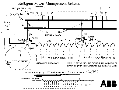
Referring now to Fig. 1, there is shown the actuator
power management system of the present invention. As is
shown in Fig. 1, all of the power supply units (PSUs) 10
are connected to a common power busbar 12, which in turn
acts as a power reservoir for the entire system of
multiple actuators 14. The PSU's 10 are of a type
designed to be connected in parallel, i.e. they contain
diodes so as to prevent the backflow of power from other
working PSUs in the event of a failure of an individual
PSU.
As is also shown in Fig. 1, actuators 14 are usually
arranged in standard group sizes such as the eight
actuators of group 14a or the six actuators of group 14b.
It should be appreciated that while actuator group sizes
having eight and six actuators are shown in Fig. 1 that
other group sizes may be considered suitable for other
actuator types or applications. It should also be
appreciated that a typical headbox or profiler may have a
hundred or more actuators and thus the two actuator
CA 02596396 2007-07-30
WO 2006/089718 PCT/EP2006/001569
6
groups 14a and 14b totaling 14 actuators is shown in Fig.
1 solely for the ease of illustration and additional
groups of actuators may also be implemented using the
same implementation scheme as is shown in Fig. 1 for
groups 14a and 14b..
Power is distributed to the actuator groups 14a and
14b through multiple power cables 16a and 16b each of
which have an associated fuse 18a and 18b, respectively.
All or several of the actuator groups associated with a
typical headbox or profiler are, as is shown in Fig. 1
for actuator groups 14a and 14b, connected in series to
form a common communications bus(es) consisting of bus
segments 20a and 20b. The power is injected onto this
common bus from power cable 16a at device 34a and from
power cable 16b at device 34b such that power is provided
for the down line actuators up to the next power
injection device. Thus, the power from cable 16a is
injected at device 34a into the bus segment 20a to
provide power for the eight actuators of group 14a and
the power from cable 16b is injected at device 34b into
the bus segment 20b downstream from the actuators of
group 14a to provide power to the actuators of group 14b.
Devices 34a and 34b are identical and the wiring for
device 34a is shown in Fig. 1. Devices 34a and 34b are
known as a Power Tee and are available as of the filing
date of this application from InterlinkBT. Devices 34a
and 34b may, or may not, include a diode, as indicated in
the diagram, depending on requirements.
As can be appreciated, the next power injection
cable location is dependant on the amount of power
required by the intervening actuators and the rating of
the cables used. For example as is shown in Fig. 2, if
the power requirements of actuator groups 14a and 14b are
low enough then the power cable 16a can supply power to
both group of actuators with the power first passing
through the actuators of group 14a and then to the
CA 02596396 2007-07-30
WO 2006/089718 PCT/EP2006/001569
7
actuators of group 14b.
Thus, in accordance with the present invention,
power may be passed through to the next group of
actuators as is shown in Fig. 2 or may be supplied
separately by breaking power connections and injecting
power into the next group using an additional power cable
and associated injector as shown in Fig. 1 for cable 16b
and injector 34b.
The present invention is intended for use with
actuators that have a low (or zero) standby (or holding)
power usage but have much higher power requirements
during actuation, resulting in a change to the actuators
position or influence, for example, 20mA at rest and
800mA during actuation. A typical example of these
actuator types are known to those of ordinary skill in
the art as electro-mechanically actuated actuators.
As is shown in Figs. 1 and 2, the actuator system of
the present invention is controlled by a single processor
unit (CPU) 22. As is shown in Fig. 3, CPU 22 in a
typical arrangement contains an algorithm 24 that
comprises a setpoint checking module 26, a power
management module 28 and a communications module 30 which
in combination actively monitors the available power and
determines the number of actuators that can be actuated
simultaneously. The setpoint module 26 may be omitted
from the arrangement as it is not essential to the
operation of the present invention. As Fig. 3 also
shows, the CPU 22 also contains the models 32 that
control the movements of the individual actuators. There
is one model for each actuator.
The setpoint checking module 26 determines if the
actuator setpoint is within limits. The module 26
receives the actuator setpoints from one or more quality
control systems (QCSs) which are connected to a paper
machine or other machine that has actuator driven
devices. A further description of the connection of the
CA 02596396 2007-07-30
WO 2006/089718 PCT/EP2006/001569
8
one or more QCSs to the actuator driven devices is found
in the `512 Application. The module 26 also determines
if the desired setpoint would cause the actuator driven
device such as a slice lip to exceed predetermined
bending constraints. If not, the module 26 communicates
with that part of the models 32 that checks for the
movement required by individual actuators.
In response, each of the models 32 request
permission to move their associated actuator if they are
deemed by the individual models 32 to require movement.
It should be appreciated that not all of the actuators
may require movement in response to a change in actuator
setpoints from the QCS. As is shown in Fig. 3 and in
more detail in Fig. 4, the models 32 in CPU 22 that
control the movements of the individual actuators must
request permission from the power management module 28
before each movement instruction is sent to an actuator.
Thus the request for permission to move the actuators is
communicated to the power management module 28. That
module determines in combination with status signals from
the PSUs 10 if sufficient power is available to move all
of the actuators that must be moved in response to the
actuator setpoints from the QCS. If sufficient power is
available the module 28 grants the request and
communicates that grant to the actuator models 32.
The models 32 then calculate the amount of movement
and direction that is needed and generates commands to
the actuators that when received by the actuators cause
the associated actuator to move the desired amount.
Those commands are communicated to the communications
module 30 which in turn transmits the step move to the
actuators.
Referring now to Fig. 4, there is shown more detail
of how the power management module 28 in combination with
the status signals from the PSUs 10 determines if there
is sufficient power to move all of the actuators that
CA 02596396 2007-07-30
WO 2006/089718 PCT/EP2006/001569
9
must be moved and what happens if sufficient power does
not exist at that time. As is shown in Fig. 4, the
module 28 compares the number of requests for movement
from the actuator models 32 with the available power
based on the tuning parameters.
If there is not sufficient power to simultaneously
honor all requests, the module 28 issues permission using
a predetermined criteria up to the maximum available
power and grants permission to the actuator models 32 as
shown in Fig. 3. That criteria can be based upon first
come, required movement amplitude, a priority level
(fixed or calculated) or other criteria chosen using
tuning parameters in the power management module 28. For
example, in a situation where the system requires the
simultaneous movement of 16 actuators, the power
algorithm 28 reviews the available power and the movement
requests. If power is available to move only 10
actuators simultaneously, the algorithm 28 issues
permission to the models 32 to move the first 10
actuators that requested the power and only allow
movement of the remaining six actuators after more power
becomes available. It should be appreciated that the 16
actuators to be moved may only be a subset of the
actuators forming the system and can be located anywhere
on the head box and in any combination of groups as each
actuator has its own model 32 and thus behaves
independently of the other actuators.
Further as each actuator completes its requested
movement, its associated model 32 releases the movement
request. This frees power for the other actuators. An
oversight routine in each actuator model 32 ensures that
the model 32 does not keeping asking for permission once
its actuator is deemed to have completed its movement.
It is to be understood that the description of the
foregoing exemplary embodiment(s) is (are) intended to be
only illustrative, rather than exhaustive, of the present
CA 02596396 2007-07-30
WO 2006/089718 PCT/EP2006/001569
invention. Those of ordinary skill will be able to make
certain additions, deletions, and/or modifications to the
embodiment(s) of the disclosed subject matter without
departing from the spirit of the invention or its scope,
as defined by the appended claims.