Note: Descriptions are shown in the official language in which they were submitted.
CA 02596457 2011-02-03
LASER LEVEL
This is a divisional of Canadian Patent Application No. 2,427,406, filed May
1,
2003, granted as Canadian Patent 2,427,406 on September 11, 2007.
Field of the Invention
[0001] This invention relates generally to laser instruments and specifically
to laser levels.
Background of the Invention
[0002] Laser levels have been used in construction for many years. They
typically seek to
produce a plane of light for a reference for construction projects. Laser
levels have been
used for large scale construction projects like commercial excavating, laying
foundations,
and installing drop ceilings. Laser levels save considerable time during
initial layout of a
construction job compared to other tools such as beam levels, chalk lines, or
torpedo
levels. Some examples of jobs where laser levels would be useful include
laying tile,
mounting cabinets, installing counter tops, and building outdoor decks.
[0003] It is an object of the present invention to provide a laser level that
is inexpensive
and usable by the general public.
Summary of the Invention
[0004] In accordance with the present invention, there is provided a laser
level disposable
on a reference surface comprising a housing; a first laser diode disposed in
the housing for
emitting a first laser beam along a first path; a first lens disposed in the
housing in the first
path for converting the first laser beam into a first planar beam, the first
planar beam
forming a first line on the reference surface; and a hanging assembly
connected to the
housing for mounting the laser level to the reference surface.
-1-
CA 02596457 2007-08-23
[0005] Additional features and benefits of the present invention are
described, and
will be apparent from, the accompanying drawings and the detailed description
below.
Brief Description of the Drawings
[0006] The accompanying drawings illustrate preferred embodiments of the
invention
according to the practical application of the principles thereof, and in
which:
[0007] FIG. 1 is a perspective view of a first embodiment of a laser level
according to
the invention;
[0008] FIG. 2 is a cross-sectional view of the laser level of FIG. 1;
[0009] FIG. 3 illustrates different laser diode/lens arrangements, where FIG.
3A is a
partial cross-sectional front view of an arrangement, and FIGS. 3B-3E are top
views of
alternate arrangements;
[0010] FIG. 4 illustrates another laser diode/lens arrangement, where FIG. 4A
is a
partial cross-sectional top view of such arrangement, FIG. 4B is an augmented
view of
FIG. 4A, FIG. 4C is a partial cross-sectional view along line IV-IV of FIG.
4B, FIG. 4D is
an augmented top drawing of the lens in FIG. 4A, FIG. 4E is an augmented top
drawing
of a first alternate lens, FIG. 4F is a front view of a second alternate lens,
and FIG. 4G is a
cross-sectional view along line G-G of FIG. 4F;;
[0011] FIG. 5 illustrates the laser level being used with a target, where
FIGS. 5A-5B
are front and top views, respectively;
-2-
CA 02596457 2007-08-23
[0012] FIG. 6 illustrates the target of FIG. 5, where FIGS. 6A-6B show the
target
independently and with the laser level, respectively;
[0013] FIG. 7 is a wall hanging assembly for the laser level;
[0014] FIG. 8 is a partial cross-section of a second embodiment of the laser
level,
where FIGS. 8A-8B show the laser level in vertical and inclined positions,
respectively;
[0015] FIG. 9 illustrates a pendulum lock mechanism according to the
invention;
[0016] FIG. 10 illustrates a third embodiment of the laser level, where FIGS.
1OA-IOC
show a laser assembly disposed on right, top and left positions, respectively,
and FIG.
I OD is an exploded diagram of the laser level;
[0017] FIG. 11 is a block diagram of the components of the laser level;
[0018] FIG. 12 is an alternate block diagram of the components of the laser
level;
[0019] FIG. 13 illustrates a fourth embodiment of the laser level, where FIGS.
13A-
13B are perspective and cross-sectional views of the laser level,
respectively; and
[0020] FIG. 14 illustrates another wall hanging assembly for the laser level.
Detailed Description
[0021] The invention is now described with reference to the accompanying
figures,
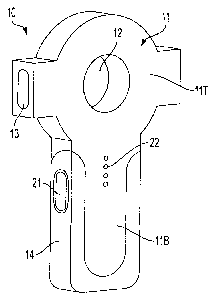
wherein like numerals designate like parts. Referring to FIGS. 1-2, a laser
level 10 may
have a housing 11. The housing 11 may have a top portion 11 T and a bottom
portion
11B. The housing may also have a hole 12 extending through the housing 11. The
hole
12 preferably extends through the top portion l IT. The perimeter of the hole
12 may be
defined by an inner wall 11I.
-3-
CA 02596457 2007-08-23
[0022] The top portion 11T may carry a pendulum assembly 30. Preferably, the
pendulum assembly 30 has a main body 31, which may be made of metal or
plastic.
Main body 31 may be disposed on a knife edge 11IK. Knife edge 1 IIK may be
connected
to and/or supported by inner wall 111. Alternatively, knife edge 11 IK may be
connected
to and/or supported by housing 11. Persons skilled in the art will recognize
that
pendulum assembly 30 may be supported by means other than knife edge 11IK,
such as a
pin, bearing, point or other pendulous means.
[0023] The main body 31 may carry at least one laser assembly 40 and
preferably two
laser assemblies 40 disposed left and right of the knife edge 11IK. Persons
skilled in the
art will recognize that a laser assembly 40 may disposed above knife edge 1
IIK. Persons
skilled in the art will also recognize that the laser assemblies 40 will emit
laser beams.
Accordingly, it is preferable to provide housing 11 with windows 13 to allow
the laser
beams to exit from housing 11.
[0024] Persons skilled in the art will recognize that such arrangement will
provide a
self-leveling pendulum assembly that will emit substantially horizontal laser
beams (and a
substantially vertical laser beam if a laser assembly 40 is disposed above
knife edge 1 l IK
and is directed upwardly) when laser level 10 is disposed against a wall.
Persons skilled
in the art will also recognize that it is preferable to allow laser assembly
40 to be
angularly adjusted along a vertical plane relative to main body 31, to ensure
that the
projected laser beam is substantially horizontal when the main body 31 is at
its stationary
position.
[0025] A possible adjustment arrangement is shown in FIG. 8A, where laser
assembly
40 has a barrel 41 carrying the laser diode and lens(es) (not shown). Barrel
41 may be
-4-
CA 02596457 2007-08-23
disposed on a pin 38 supported by main body 31. A spring 39 preferably
disposed
between barrel 41 and main body 31 may bias barrel 40 upwardly against set
screw 37.
Set screw 37 is preferably disposed on main body 31 and contacts barrel 41 to
stop
rotation of barrel 41 about pin 38, and set the position of barrel 41 (and
thus of laser
assembly 40). Persons skilled in the art will recognize that the set screw 37
is preferably
locked in place using a locking compound such as Loc-Tite.
[0026] A second possible adjustment arrangement is also shown in FIG. 8A,
where
like numerals refer to like parts. In this arrangement, barrel 41 may be
disposed against a
protrusion 31P by main body 31. A spring 39' preferably disposed between
barrel 41 and
main body 31 may bias barrel 40 downwardly against set screw 37. Set screw 37
is
preferably disposed on main body 31 and contacts barrel 41 to stop rotation of
barrel 41
about protrusion 31P, and set the position of barrel 41 (and thus of laser
assembly 40).
Persons skilled in the art will recognize that the set screw 37 is preferably
locked in place
using a locking compound such as Loc-Tite.
[0027] Referring to FIGS. 1-2, main body 31 may also have weights 33 to
provide a
lower center of gravity, and enhance the performance of the pendulum assembly
30. In
addition, main body 31 may have at least one adjustment screw 33A to adjust
the center
of gravity of pendulum assembly 30, as necessary.
[0028] Main body 31 may also have a plaque 33M, made of magnetic material,
ferrous material or non-ferrous conductive material, such as zinc or copper.
Plaque 33M
preferably is aligned with at least one magnet (and preferably two magnets)
disposed in
housing 11, e.g., on the inside of the front and rear walls of housing 11, for
providing a
damping action on pendulum assembly 30. Basically, eddie currents are
generated within
-5-
CA 02596457 2009-12-10
plaque 33M, as the plaque moves and interacts with the magnetic field supplied
by the
magnet(s).
[0029] Persons skilled in the art shall recognize that pendulum assembly 30 is
preferably wholly contained within housing 11. However, the pendulum assembly
30
may be at least partly, if not completely, disposed outside of housing 11.
[0030] Persons skilled in the art shall recognize that a damping mechanism for
damping the motion of pendulum assembly 30 may be provided. Persons skilled in
the
art are directed to the damping mechanism disclosed in US Patent No.
5,144,487.
[0031] The bottom portion 11B of housing 11 may carry a battery 50 for
powering the
laser assemblies 40. In addition, the bottom portion 11 B may carry a stud
sensor circuit
20. The circuitry of the stud sensor circuit 20 is not illustrated herein.
Persons skilled in
the art are referred to U.S. Pat. Nos. 4,099,118 and 4,464,622.
[0032] As is well known in the art, the stud sensor circuit 20 may include an
on/off
actuator or switch 21, which can be a push-button type actuator. Stud sensor
circuit 20
may also include light emitting diodes 22 to display the location of a stud.
[0033] It is preferable to align the sensors within stud sensor circuit 20
with the center
of hole 12, so that the center of hole 12 indicates the location of the stud.
[0034] Persons skilled in the art should recognize that detector circuits
other than stud
sensor circuit 20 may be provided in laser level 10. Preferably, these
detector circuits can
detect features underneath a surface, such as a wall or floor. These features
may include
-6-
CA 02596457 2007-08-23
pipes or wires. Circuits for pipe and wire detectors, as well as other
detector circuits, are
well known in the art.
[0035] The housing 11 may be formed from a hard impact resistant, preferably
moldable material such as a hard thermoplastic material such as ABS or
polystyrene. It is
preferable to provide a grip 14 on bottom portion 11 B. Grip 14 may be made of
a soft or
low durometer thermoplastic elastomer. In addition, grip 14 can be formed from
any of
the so-called "soft-touch" elastomer materials, such as those sold under the
tradenames
"Santoprene", "Kraton" and "Monprene," and are preferably adhered or
overmolded to the
housing 11.
[0036] Referring to FIGS. 2-3, laser assemblies 40 are disposed on main body
31.
Laser assembly 40 may include a substantially cylindrical barrel 41, which may
be
adjustably connected to main body 31, laser diode 42 disposed in barrel 41,
and a line
lens 43 disposed in barrel 41. Persons skilled in the art will recognize that
in the
preferred embodiment, adjusting barrel 41 will result in moving laser diode 42
and line
lens 43. In addition, persons skilled in the art will recognize that a
collimating lens may
be disposed between laser diode 42 and line lens 43.
[0037] Preferably, line lens 43 converts the laser beam exiting laser diode 42
into a
planar beam. Line lens 43 may have different shapes to accomplish such
purpose. For
example, as shown in FIG. 3B-3D, line lenses 43A, 43B, 43C may have a
substantially
circular cross-section, half-circle cross-section or quarter-circle cross-
section,
respectively. Alternatively, line lens 43D may have a compound cross-section,
which
includes a rectangle connected to a quarter-circle.
-7-
CA 02596457 2007-08-23
[0038] Accordingly, when laser level 10 is disposed against a wall, laser
assembly 40
will preferably emit a laser plane that contacts the wall, forming a laser
line on the wall.
Persons skilled in the art will recognize that it is preferable to orient the
laser assemblies
40 in such manner so that at least a portion of the laser plane will contact
the wall. In
addition, persons skilled in the art will recognize that providing laser
assemblies 40 on
the pendulum assembly 30 discussed above will preferably result in laser level
10
projecting substantially horizontal laser lines against the wall (and a
substantially vertical
laser beam if a laser assembly 40 is disposed above knife edge 1 IIK and is
directed
upwardly).
[0039] Persons skilled in the art will recognize that line lenses 43B, 43C,
43C will
limit the angle of plane divergence. In other words, if a horizontal line HL
is 0 , the
plane exiting from line lens 43A may extend from, for example, -30 to 30 ,
providing an
angle of plane divergence DA of 60 . On the other hand, the plane exiting from
line
lenses 43B, 43C, 43D may extend from, for example, 0 to 30 , providing an
angle of
plane divergence DA of 30 . This provides for a more efficient use of the
laser beam,
directing more energy towards the wall, rather than away from the wall.
Persons skilled
in the art will recognize that directing more energy towards the wall is
preferable as it
would result in a brighter laser line on the wall.
[0040] A preferred laser assembly 40' is shown in FIG. 4, where like numerals
refer
to like parts. Such laser assembly 40' has a collimating lens 44 disposed in
the laser
beam path, as well as a line lens 45 disposed in the laser beam path after the
collimating
lens 44. Line lens 45 is preferably a prismatic lens that includes at least
two cylindrical
-8-
CA 02596457 2007-08-23
lens forms with significantly different focal distances to generate at least
two
superimposed laser planes with different divergence angles and trajectories.
[0041] With such arrangement, when laser assembly 40' is placed near a wall W,
two
or more lines are projected onto wall W. At least one of these lines (L1) may
be directed
to strike the wall W at a short distance along the wall surface, while another
of these lines
(L2) may be directed to strike the wall W at a longer distance. This
preferably increases
the overall length and/or apparent brightness of the laser line shown on the
wall W.
Lines L1, L2 may partially overlap or may be separated to further increase the
length of
the resulting laser line on wall W.
[0042] As mentioned above, line lens 45 may have two portions. One portion has
a
long focal distance for generating the high density line L2, i.e., having a
small divergence
angle. The brightness of line L2 along wall W will depend of the divergence
angle H, as
the smaller the divergence angle, the brighter the line at a given distance.
[0043] But a small divergence angle H will result in a laser line gap on the
wall W
between the laser assembly 40' (and thus laser level 10) and the beginning of
line L2.
Accordingly, it is preferable to provide line lens 45 with a second portion
with a short
focal distance for generating a line L1 with lower density than the line L2,
and thus
having a larger divergence angle L. The larger divergence angle L will create
a low
density line L1 that will contact wall W closer to the laser assembly 40',
thus reducing the
laser line gap left by line L2.
[0044] Persons skilled in the art will recognize that the first and second
portions will
have a first and second radii R1, R2, respectively. Preferably, radius R1 is
substantially
larger than radius R2. Persons skilled in the art will know how to select the
appropriate
-9-
CA 02596457 2007-08-23
radii, as they must be selected based on the distance from the wall W to laser
assembly
40', the desired length of laser line gap to fill up, etc.
[0045] Persons skilled in the art will recognize that the laser beam LB
created by the
collimating lens 42 has a generally oval cross-section. The use of the long
axis of the
oval allows easier positioning of the beam to pass the two portions of line
lens 45. It is
desirable to orient the laser beam LB so that the short axis of the oval is
aligned in the
axis of the line lens 45 that offers no or minimal magnification. Accordingly,
the short
axis preferably provides the width of laser lines L1, L2. Persons skilled in
the art will
recognize that a narrower width is preferable as it increases accuracy and
intensity of the
laser lines. In a preferred embodiment, the short and long axes are about 3 mm
and about
7 mm respectively.
[0046] Persons skilled in the art will also recognize that the above
discussion is
preferably applicable to line lens 45, as well as to alternate line lens 45'
(FIGS. 4E-4G),
except that the second portion with R2 is concave, i.e., extending into the
lens, rather
convex, i.e., extending out of the lens. In the embodiment of FIGS. 4F-4G,
line lens 45'
has radii R1, R2 of about 12.70 mm and about 0.75 mm, respectively.
[0047] It may also be preferable to provide line lens 45' with protrusions 45P
to
engage barrel 41.
[0048] Furthermore, it is preferable to provide a means of line lens 45' to
delimit the
width of the laser plane generated by laser assembly 40'. One such means is by
providing
a screen 45S on the wall 45F closest to laser diode 42. With such screen 45S,
the shape
or width of the emitted laser plane can be controlled. For example, screen 45S
can define
an unscreened line through which the laser beam is transmitted.
-10-
CA 02596457 2007-08-23
[0049] In the present embodiment, screen 45S is basically a texture molded
onto wall
45F. However, persons skilled in the art will recognize that screen 45S can be
an opaque
material, such as paint, metal or fabric, which is disposed on or adjacent to
line lens 45'.
Furthermore, screen 45S could be disposed on or adjacent to wall 45R, or
within line lens
45'. Alternatively, screen 45S can be disposed ahead of lens 44.
[0050] Referring to FIG. 5, regardless of the type of line lens used, it is
likely that the
laser line will fade as it gets farther from laser level 10. As shown in FIG.
5B, the
emitted laser plane LP still has a component that does not contact the wall W.
This
component will form a laser line when it contacts another surface.
[0051] Accordingly, it is preferable to provide a surface that can intersect
this
component of the laser plane LP. This surface can be provided on a movable
target 60.
Target 60 may have a main body 61, and a cylinder 62 disposed on the body 61.
Preferably, the inside of cylinder 62 is carved out, forming a hollow cone 62C
ending in a
central bore 63. Target 60 may have cross-hair indicia, such as grooves 65 or
ribs,
intersecting at the center of bore 63.
[0052] Persons skilled in the art will recognize that target 60, main body 61
and/or
cylinder 62 may be made of a translucent material to facilitate location of a
mark. This
could facilitate placing the laser level 10 on a specifically desired
location.
[0053] A ramp 64 may be provided on cylinder 62. Preferably the ramp 64 has
some
reflective material. (Alternatively, textured areas can be disposed on
cylinder 62 or ramp
64 to enhance the visibility of the laser line.) Accordingly, the user can
disposed the
laser level 10 on wall W and move target 60 until ramp 64 is aligned with the
laser line.
-11-
CA 02596457 2007-08-23
[0054] The user can then use a pencil to mark the center of target 60.
Alternatively,
the user can push a pin 66P or expanding mandrel 66M through bore 63 to
maintain the
target 60 in place. Persons skilled in the art will recognize that an
expanding mandrel has
at least two metal strips along its longitudinal axis meeting at a front tip.
The mandrel is
inserted into a pre-drilled hole. The steel strips can be then expanded within
the hole in
order to fix the mandrel.
[0055] Persons skilled in the art will recognize that target 60 may be
removably
disposed in hole 12 of laser level 10. Thus, laser level 10 provides on-board
storage for
target 60. To this end, it is preferable to provide target 60 with detent
protrusions 67,
which engage the laser level 10.
[0056] Persons skilled in the art will recognize that, if the center of hole
12 is aligned
with the horizontal lines emitted by the laser assemblies 40, the bore 63 of
target 60 will
be placed at the intersection of the vertical centerline of laser level 10
with the horizontal
lines. In addition, the laser level 10 may be hung by pushing a pin through
bore 63 and
nesting laser level 10 unto target 60.
[0057] It may also be preferable to provide a hanger assembly 70 for laser
level 10.
Hanger assembly 70 may have a main body 71 with a central hole 72 for
receiving the
head of a nail hammered into a wall. Main body 71 may be made of a translucent
material to facilitate location of a mark or nail.
[0058] Hanger assembly 70 may also have a ramp 73, as cross-hair indicia, such
as
grooves 74 or ribs, intersecting at the center of hole 72. Textured areas can
be disposed
on main body 71 or ramp 73 to enhance the visibility of the laser line.
-12-
CA 02596457 2011-02-03
100591 Hanger assembly 70 may be removably disposed in hole 12 of laser level
10. To
this end, it is preferable to provide hanger assembly 70 with detent
protrusions 77, which
engage the laser level 10.
100601 Persons skilled in the art will recognize that housing 11 may be
provided with
holes for receiving nail heads or screw heads, for hanging laser level 10
thereon.
100611 It may also be preferable to provide a separable hanger assembly 90
(see Fig. 14)
for laser level 10. Hanger assembly 90 may have a main body 91, a magnet 93
disposed on
the main body 91, and a ramp 92. Main body 91 may also have cross-hair
indicia, such as
grooves or ribs, intersecting at its center. Hanger assembly 90 may be
removably disposed
in hole 12 of laser level 10. To this end, it is preferable to provide hanger
assembly 90
with detent protrusions 94, which engage the laser level 10.
[00621 Main body 91 may magnetically engage another assembly, such as wall
assembly
95, pin assembly 96 and/or mandrel assembly 97. Wall assembly 95 preferably
has a body
95B, a magnetically-responsive metal plate 95MP supported by body 95B, and a
hole
95H. Basically, the user can dispose wall assembly 95 on a nail or screw on a
wall. The
user can then dispose main body 91 unto wall assembly 95, which will stay
together
because of the magnet/metal plate combination.
[00631 Pin assembly 96 preferably has a body 96B, a magnetically-responsive
metal plate
96MP supported by body 96B, and a pin 96P. Basically, the user can dispose pin
assembly
96 unto a wall. The user can then dispose main body 91 unto pin assembly 96,
which will
stay together because of the magnet/metal plate combination.
[00641 Mandrel assembly 97 preferably has a body 97B, a magnetically-
responsive metal
plate 97MP supported by body 97B, and a mandrel 97M. Basically, the user can
-13-
CA 02596457 2007-08-23
dispose mandrel assembly 97 within a pre-drilled hole on a wall. The user can
then
dispose main body 91 unto mandrel assembly 97, which will stay together
because of the
magnet/metal plate combination.
[0065] Persons skilled in the art will recognize that it is also preferable to
provide a
rib 98 on main body 91 that receives wall assembly 95, pin assembly 96 and/or
mandrel
assembly 97, or a portion thereof. Preferably, the rib 98 is designed so that,
when main
body 91 is disposed on wall assembly 95, pin assembly 96 and/or mandrel
assembly 97,
the main body 91 is centered relative to the opposite assembly. Rib 98 may
also support
main body 91 (and thus laser level 10). Persons skilled in the art will
recognize that the
rib 98 may be disposed on wall assembly 95, pin assembly 96 and/or mandrel
assembly
97. Alternatively, rib 98 may be received within a slot or groove of wall
assembly 95, pin
assembly 96 and/or mandrel assembly 97.
[0066] A second embodiment of laser level 10 is shown in FIG. 8, where like
numerals refer to like parts. The teachings of the first embodiment above are
wholly
incorporated by reference in the present embodiment. One difference from the
previous
embodiment is that the pendulum assembly 30 has a knife edge 36 disposed
therein,
which engages a notch 11N in housing 11. In addition, pendulum assembly 30 may
have
a lower curved area 35.
[0067] It is preferable to dispose laser assemblies 40 within protrusions 15
of top
portion 11T. With such arrangement, when the laser level 10 is disposed
substantially
vertically against a wall, laser beams emitted by laser assemblies 40 can exit
housing 11
through windows 13. As discussed above, the laser level 10 has a certain angle
range,
where the laser level 10 can be disposed at an angle relative to the vertical
centerline V
-14-
CA 02596457 2007-08-23
and the pendulum assembly 30 will self-level and emit substantially horizontal
(or
vertical) laser beams.
[0068] If the laser level 10 is disposed at an angle beyond the angle range,
laser
assemblies 40 may contact the inner walls of protrusions 15. Alternatively,
pendulum
assembly 30 may contact a component disposed within housing 11. When this
occurs,
the laser level 10 will no longer provide an accurate leveling function.
[0069] Preferably, the windows 13 are sized to prevent the emitted laser beams
to
project out of housing 11 when the laser assemblies 40 contact the inner walls
of
protrusions 15 or pendulum assembly 30 contacts a component disposed within
housing
11. This prevents the user from believing that the emitted laser beams are
substantially
horizontal (or vertical).
[0070] Preferably, the windows 13 prevent the laser beams from exiting the
housing
when the pendulum assembly 30 approach the limits of the angle range. In other
words,
assuming an angle range being between about -10 to about 10 from vertical
centerline
V where pendulum assembly 30 will self-level, and where the laser assemblies
40 contact
the inner walls of protrusions 15 or pendulum assembly 30 contact a component
disposed
within housing 11 at any angle beyond this angle range, it may be preferable
to size
and/or shape the windows 13 to begin blocking the laser beams at about -8
and/or about
8 from vertical centerline V.
[0071] It may be preferable to provide a pendulum lock mechanism 80 for
locking
pendulum assembly 30 at a certain position. For example, pendulum assembly 30
may be
locked in place in order to safely transport laser level. Pendulum lock
mechanism 80 may
include a lock 84 that has a locking surface 84LR which contacts a portion of
pendulum
-15-
CA 02596457 2007-08-23
assembly 30, such as curved area 35. Lock 84 is preferably movable along its
axis
between locked and unlocked positions. A spring 86 may be trapped between
housing 11
(via boss 11B) and lock 84 for biasing lock 84 towards the locked position.
[0072] Lock 84 may be moved between the locked and unlocked positions by an
actuator 83. The longitudinal axis of actuator 83 is preferably substantially
perpendicular
to the longitudinal axis of lock 84. Actuator 83 may be moved along its axis
between a
first position that moves lock 84 into the locked position and a second
position that
moves lock 84 into the unlocked position. Preferably, actuator 83 and lock 84
have
ramps 83R, 84R, respectively, for contacting therebetween.
[0073] As shown in FIG. 9, actuator 83 is shown in the first and second
positions
with solid and broken lines, respectively. As actuator 83 is moved upwardly,
ramp 83R
contacts ramp 84R, and moves lock 84 towards the unlocked position. Actuator
83 may
have a plateau 83P disposed at the end of ramp 83R for maintain lock 84 in the
unlocked
position.
[0074] Actuator 83 may have an actuator button 81 to enable the user to move
the
actuator 83 between the first and second positions (and thus to move the lock
84 between
the locked and unlocked positions).
[0075] Persons skilled in the art will recognize that actuator 83 may be
connected to a
switch 82, so that when actuator 83 is moved, switch 82 is activated.
Preferably, switch
82 turns laser assemblies 40 on and off.
[0076] Persons skilled in the art should also recognize that the spatial
relationship
between actuator ramp 83R, lock ramp 84 and the travel distance of switch 82
can be
manipulated so that the switch 82 will turn on laser assemblies 40 only when
lock 84 is
-16-
CA 02596457 2007-08-23
moved to the unlocked position. Alternatively, the spatial relationship
between actuator
ramp 83R, lock ramp 84 and the travel distance of switch 82 can be manipulated
so that
the switch 82 will turn on laser assemblies 40 before lock 84 is moved to the
unlocked
position. This allows the user to use the laser level 10 to emit straight
laser lines, even
though these lines are not necessarily level.
[0077] A third embodiment of laser level 100 is shown in FIG. 10, where like
numerals refer to like parts. The teachings of the embodiments discussed above
are
incorporated herein by reference.
[0078] Laser level 100 basically has three assemblies: base assembly 110,
pendulum
assembly 120 and laser housing assembly 130. These three assemblies may be
designed
so that they cannot be separated during operation. Alternatively these three
assemblies
may be designed so that they can be separated during operation and/or storage.
[0079] Base assembly 110 has a main body 111, which has a substantially flat
rear
wall to ensure that laser level 100 can be disposed substantially flush
against a wall.
Main body 111 may a central hollow cylinder 112. In addition, main body 111
may carry
the stud sensor circuit 20.
[0080] Pendulum assembly 120 preferably has a main body 121 and a hole 121H on
body 121 for nesting pendulum assembly 120 on cylinder 112. Preferably, main
body
121 (and thus pendulum assembly 120) can rotate about cylinder 112.
Accordingly, it is
preferable to dispose bearings 123 therebetween to facilitate such rotation.
[0081] Main body 121 may have a compartment for receiving battery 50. In
addition,
main body 121 may have an annular protrusion 122.
-17-
CA 02596457 2007-08-23
[0082] Laser housing assembly 130 may have a housing 131 and at least one
laser
assembly 40 disposed within the housing 131. Housing 131 may have a hole 131H
for
nesting laser housing assembly 130 onto protrusion 122. Preferably housing 131
(and
thus laser housing assembly 130) can rotate about protrusion 122. Accordingly,
it is
preferable to dispose bearings 126 therebetween to facilitate such rotation.
[0083] A detent mechanism 140 may be disposed between pendulum assembly 120
and laser housing assembly 130 for fixing the rotational position of laser
housing
assembly 130 (and thus of laser assembly 40) relative to the pendulum assembly
120.
Detent mechanism 140 may comprise a detent ball 144 which engages a notch (not
shown) on housing 131. A spring 145 is preferably disposed between body 121
and ball
144 to bias ball 144 towards the notch. Persons skilled in the art will
recognize that the
spring 145 and ball 144 may alternatively be disposed on housing 131, whereas
the notch
can alternatively be disposed on body 121.
[0084] Preferably, the notches are disposed in such locations so that the
laser
assembly 40 will emit a laser beam that is at 90 of the vertical axis of
pendulum
assembly 120 (i.e., emitting a laser beam towards the right of laser level
100, as shown in
FIG. I OA), at 0 of the vertical axis of pendulum assembly 120 (i.e.,
emitting a laser
beam upwardly, as shown in FIG. I OB), or at -90 of the vertical axis of
pendulum
assembly 120 (i.e., emitting a laser beam towards the left of laser level 100,
as shown in
FIG. I OC). Persons skilled in the art will recognize that the notches may be
disposed on
other positions.
[0085] With such arrangement, the user can dispose laser level 100 against a
wall.
The user can move laser level 100 along the wall until a stud is detected by
stud sensor
-18-
CA 02596457 2007-08-23
circuit 20. While holding on to main body 111, the user can let pendulum
assembly 120
and laser housing assembly 130 self-level, so that the emitted laser beam will
be
substantially horizontal or vertical. The user can also rotate laser housing
assembly 130
to the different desired positions.
[0086] In all three embodiments, the battery 50 preferably provides power to
both
stud sensor circuit 20 and laser diode(s) 42, as shown in FIG. 11, so that the
stud sensor
circuit 20 and laser diode(s) 42 operate independently from each other.
Persons skilled in
the art will recognize that it may be desirable to enable the stud sensor 20
to control the
laser diode(s) 42, so that the laser diode(s) 42 only turn on when a stud is
detected by stud
sensor 20.
[0087] Another embodiment of the novel laser level is shown in FIG. 13, where
like
numerals refer to like parts. The teachings of the embodiments above are
wholly
incorporated by reference in the present embodiment. Like before, laser level
10 has laser
assemblies 40 for projecting laser beams, preferably in the form of planes.
Furthermore,
laser level 10 has a stud sensor circuit 20.
[0088] In this embodiment, the main difference is that the laser assemblies 40
are not
disposed on a pendulum. Instead, they are fixedly connected to housing 11.
Accordingly,
the user can disposed housing 11 at any position against a wall or floor, and
two laser
lines will be emitted unto the wall or floor.
[0089] A horizontal bubble vial 11HV may be provided on housing 11 to indicate
to
the user when the laser beams are level, i.e., substantially horizontal.
Similarly, a vertical
bubble vial 11 VV may be provided on housing 11 to indicate to the user when
the laser
beams are plumb, i.e., substantially vertical. Persons skilled in the art will
recognize that
-19-
CA 02596457 2007-08-23
other means for detecting and indicating whether the laser beams are plumb or
level can
be used. In addition, persons skilled in the art will recognize that it may be
preferable to
dispose at least one laser assembly 40 at 90 from another laser assembly 40,
to emit a
perpendicular laser beam or line.
[0090] Persons skilled in the art may recognize other additions or
alternatives to the
means disclosed herein. However, all these additions and/or alterations are
considered to
be equivalents of the present invention.
-20-