Note: Descriptions are shown in the official language in which they were submitted.
CA 02596707 2007-08-09
STEAM CLEANER AND STEAM IRON APPARATUS
FIELD OF THE INVENTION
The present invention relates to steam cleaners and steam irons and, more
particularly, to an improved steam cleaner and steam iron apparatus.
BACKGROUND OF THE INVENTION
Steam cleaning appliances require a substantial amount of power to operate
properly.
Typically, steam cleaning appliances require around 1500 watts of power (1800
watts
maximum) to sufficiently heat stored water to provide the necessary steam for
the cleaning
appliance.
Similarly, steam generating irons require a substantial amount of power to
operate
properly. Steam generating irons generally include two heating elements, one
to heat the iron
and the other to heat water to produce steam. In the United States, the
combined amount of
electrical power utilized by both heating elements, for practical purposes,
exceed 1800 watts
due to UL regulations limiting voltage levels to 120 volts, with a maximum
draw of 15 amps
at this voltage level. A combined steam cleaner and steam iron includes a base
unit (having a
boiler tank, heating element, power switch and safety devices) with both a
detachable steam
cleaner accessory and a steam iron accessory; only one of the accessories may
be used at one
time. The combined wattage of the base and the iron may not exceed 1800 watts.
Given these power constraints, a device that combines a steam cleaner with a
steam
iron would not be able to draw sufficient power to power the separate heating
elements of the
combined device. One attempt to overcome this problem is disclosed in European
Patent No.
EP 0 809 728 B1. The design shown therein is intended for use in Europe, which
generally
has line voltage of 220 volts and power standards suitably high that provide
sufficient power
to a device that includes both a steam cleaner and a steam iron.
A combined steam cleaner and steam iron apparatus which overcomes the problem
of
power constraint in the U.S. is described in commonly owned U. S. Patent No.
6,711,840,
-1-
CA 02596707 2007-08-09
incorporated by reference herein. However, the apparatus described in the '840
patent
requires two separate heating elements for the boiler. There remains a need
for a combined
steam cleaner and steam iron with a reduced number of components necessary to
perform the
desired function (that is, a single boiler heating element), thus reducing the
cost of the
combined unit.
It therefore is desirable to provide a simple, low cost, combined steam
cleaner and
steam iron apparatus designed to properly operate under restricted power
requirements. In
particular, it is desirable that the apparatus be able to regulate the power
drawn by the boiler
under various conditions, such as when heating the iron.
SUMMARY OF THE INVENTION
The present invention addresses the above-described need by providing a
combination steam cleaner and steam iron that includes a steam generator, a
steam cleaner
and a steam iron. The steam generator includes a control device connected to a
boiler element
for boiling water to produce steam. The steam iron includes an iron heating
element and a
thermostat. The steam generator receives a maximum amount of power except when
the iron
thermostat is closed and the iron heating element requires power; the amount
of power
delivered to the boiler element is then reduced. The control device may
include a circuit
configured to deliver electrical power to the boiler element with a preset
duty cycle, so that
the reduced amount of power is a fraction of the maximum power in accordance
with the
duty cycle.
The control device may include a half-wave rectifier for delivering electrical
power to
the first heating element with a 50% duty cycle, so that the reduced amount of
electrical
power is 50% of the maximum amount. The control device may further include a
relay
energized in accordance with the iron thermostat being in the closed state,
the relay thereby
coupling the half-wave rectifier to the boiler heating element.
The control device may also include a gated conductor device and a timer
device,
where the gated conductor device is configured to conduct current in
accordance with a
-2-
CA 02596707 2007-08-09
signal at the gate from the timer device. The duty cycle is preset in
accordance with values
of resistances coupled to the timer device.
The boiler element is preferably a 1500 watt (up to 1800 Watt) heater and the
iron
heating element is preferably a 600 watt heater. About 1500 watts of power are
drawn
during use of the steam cleaner and about 1500 watts of power are drawn during
use of the
steam generator and the steam iron.
BRIEF DESCRIPTION OF THE DRAWINGS
For a more complete understanding of the present invention and the advantages
thereof, reference is now made to the following description taken in
conjunction with the
accompanying drawings in which like reference numbers indicate like features
and wherein:
FIG. 1 illustrates a combined steam cleaner and steam iron apparatus in
accordance
with the present invention, shown with the steam iron attached.
FIG. 2 shows the combined steam cleaner and steam iron apparatus in accordance
with the invention, shown having the steam cleaner attached.
FIG. 3 shows an embodiment of a heating element used within the combined steam
cleaner and steam iron apparatus of FIG. 1 and FIG. 2.
FIG. 4 is a schematic illustration of an electrical circuit of the combined
steam
cleaner and steam iron apparatus of FIG. 1 and FIG. 2, according to an
embodiment of the
invention.
FIG. 5A is a schematic illustration of an electrical circuit for a combined
steam
cleaner and steam iron apparatus in which power to the boiler is regulated
using a half-wave
rectifier, so as to deliver power to the boiler with a 50% duty cycle, in
accordance with
another embodiment of the invention.
FIG. 5B is a schematic illustration of an alternative arrangement of an
electrical
circuit regulating power to the boiler using a half-wave rectifier, in
accordance with another
embodiment of the invention.
-3-
CA 02596707 2007-08-09
FIG. 6 is a schematic illustration of another alternative arTangement of an
electrical
circuit regulating power to the boiler using a half-wave rectifier, in
accordance with a further
embodiment of the invention.
FIG. 7 is a schematic illustration of another altemative arrangement of an
electrical
circuit regulating power to the boiler using a half-wave rectifier, in
accordance with still
another embodiment of the invention.
FIG. 8 is a schematic illustration of an electrical circuit regulating power
to the boiler
with a preset duty cycle other than 50%, in accordance with another embodiment
of the
invention.
FIG. 9A is a schematic illustration of an alternative electrical circuit
regulating power
to the boiler with a preset duty cycle other than 50%, in accordance with
further embodiment
of the invention.
FIG. 9B is a schematic illustration of an another altetnative electrical
circuit
regulating power to the boiler with a preset duty cycle other than 50%, in
accordance with
still another embodiment of the invention.
FIG. 10 is a logic diagram applicable to several embodiments of the invention,
illustrating the state of regulated power drawn by the boiler in accordance
with the state of
the steam iron thermostat.
DETAILED DESCRIPTION OF PREFERRED EMBODIMENTS
The present invention will now be described more fully hereinafter with
reference to
the accompanying drawings, in which embodiments of the invention are shown.
This
invention may, however, be embodied in many different forms and should not be
construed
as limited to the embodiments set forth herein. Rather, these embodiments are
provided so
that this disclosure will be thorough and complete, and will fully convey the
scope of the
invention to those skilled in the art.
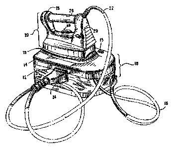
Figures 1 and 2 collectively illustrate a combined steam cleaner and steam
iron
apparatus, in accordance with an embodiment of the invention. The combined
steam cleaner
and steam iron apparatus includes a steam generator (boiler) unit 10, a steam
iron unit 20 and
-4-
CA 02596707 2007-08-09
. =
a steam cleaner unit 30. Boiler unit 10 has a single heating element. Figure 1
shows a boiler
unit 10 in the base of the apparatus, with a steam iron 20 resting on top of
and physically
attached to the base via a steam iron hose 22. Figure 2 shows a steam cleaner
30 resting on
top of and physically attached to the base via a steam cleaner hose 32.
The steam generator includes a pressostat, a thermost.at, and/or a thermofuse
serially
coupled to the boiler heating element. The steam generator also includes a top
surface
designed for use as a resting surface on which either the steam cleaner or the
steam iron may
be mounted. The top surface is designed to support a heated steam iron.
Boiler unit 10 receives electrical power via a power cable 16 that is
connected to a
suitable power receptacle during operation of the apparatus of the invention.
Boiler unit 10
includes within its housing 14 a main on/off switch (with on/off light) 15 and
also includes a
heating element 18 with electrical connections thereto, shown in Figure 3. As
further
discussed below, heating element 18 is located in the boiler unit and provides
steam for use
by both the steam iron and the steam cleaner of the invention. As best shown
in Figure 2, the
base of the apparatus includes a top surface 19 designed for use as a resting
surface for either
the steam iron 20 or the steam cleaner 30.
Referring back to Figure 1, steam iron hose 22 extends from the steam iron 20
and a
steam iron plug 24 (also called connector) extends from the other end of the
steam iron hose
22. Steam iron plug 24 is insertable into (i.e., can mate with) a socket 12
disposed within the
housing 14 of the steam generating unit 10. As shown in the exemplary design
of Figure 1,
steam iron 20 includes a handle 26, an on/off switch 28 and an on/off light
29. During use of
the steam iron 20 of the invention, the steam iron plug 24 is inserted into
socket 12.
Referring to Figure 2, steam cleaner hose 32 extends from the steam cleaner 30
and a
steam cleaner plug 34 extends from the other end of the steam cleaner hose 32.
Like the
steam iron plug 24, the steam cleaner plug 34 also can be inserted into socket
12 of the steam
generator's housing 14. The steam cleaner 30 includes an on/off switch 36 and
a nozzle 38
through which steam is supplied, as further discussed below. The steam cleaner
30 may also
include a hand grip 39 for comfort.
In order to conform to the wattage constraints discussed above, the electrical
current
delivered to (and hence the power drawn by) heating element 18 is regulated
according to the
state of the thermostats (that is, on/off or heat/no heat) of the boiler unit
and the steam iron
-5-
CA 02596707 2007-08-09
unit. Various circuits and arrangements for regulating the power drawn by the
boiler are
described in more detail below.
Three-pole iron unit thermostat with limiting circuit
Figure 4 is a schematic illustration of an electrical circuit of a combined
steam cleaner
and steam iron apparatus, in accordance with an embodiment of the invention.
When the
apparatus is in use, power cable 16 is coupled to an appropriate 120 volt
power source (line
connection L, typically rated at 15 Amps) with a return line and a ground
connection. The
power source is supplied to both the main on/off switch 15 disposed within the
steam
generating unit's housing 14, as well as to a steam release valve or solenoid
50 disposed
within the boiler unit 10. The output (also called switched power herein) of
the main on/off
switch 15 is supplied to control device 70, wherein the control device 70
includes a limiting
circuit (not shown) that regulates the maximum power that boiler heating
element 18 can
generate by a factor that can be predetermined by a manufacturer. Boiler
heating element 18
is a 1500 watt (up to 1800 watt) heater device and operates to boil water
within the steam
generating unit 10 during use of either the steam cleaner 30 or the steam iron
20. Boiler
element's 18 supply line is connected in series with two safety devices: a
thermostat 54 and a
thermofuse or cutoff 56. The respective operations of these various safety
devices are well
known in the art and thus further description is not provided herein. A
neutral terminal N is
connected to steam release valve 50 and connected to boiler element 18.
Socket 12 has five electrical contacts, A-D and ground, and a steam hose
connection
E. The switched output from main on/off switch 15 is supplied to contact B of
the steam
generator unit's socket 12, and contact A of socket 12 is connected to the
neutral terminal of
power cable 16. Contact C connects between control device 70 and boiler
element 18. The
supply line to boiler element 18 is connected to safety devices 54 and 56
mentioned above.
As fiuther discussed below, power supplied to contact B is routed back through
contact C
and then to boiler element 18 when the steam cleaner 30 is in use. When the
steam iron is in
use, power supplied to contact B is supplied to an iron element heater 25
disposed within the
steam iron 20, wherein iron heating element's 25 supply line is connected in
series through a
safety device (thermal cutoff 21) and three-contact thermostat 23 to be
explained in detail
-6-
CA 02596707 2007-08-09
hereinafter. The operation of a thermal cutoff is well known in the art and
thus further
description is not provided herein.
Neutral terminal N is connected to steam release valve 50, as previously
mentioned,
and the valve's supply line is coupled to contact D of socket 12. Contact A of
socket 12 is
coupled to the neutral line. Both steam iron 20 and steam cleaner 30 include
respective
on/off switches 28 and 36. When either the steam iron or the steam cleaner is
connected to
boiler unit 10 (via their respective plugs 24 and 34), switching the steam
on/off switch 28 or
36 of the attached device (steam iron 20 or steam cleaner 30) to the "on"
position completes
the circuit through steam release valve 50, thus causing steam to be released
from boiler unit
via hose connection E (also called the steam output port) within socket 12
through the
particular hose attached (22 or 32), and then to the pardcular device in use
(steam iron 20 or
steam cleaner 30). As can be seen in Figure 4, the on/off switch (either 28 or
36) of the
attached device (the steam iron or the steam cleaner) controls steam release
valve 50 while
power is being supplied to the boiler heater.
The steam iron 20 contains an electrical circuit as shown in Figure 4. Plug 24
includes electrical contacts A', B', C', D' and ground, which mate with
contacts A, B, C, D
and ground, respectively, of the steam generator's socket 12 when plug 24 and
socket 12 are
attached to one another. Contact B' is connected to a thermal cutoff 21 which
connects to a
three contact iron thermostat 23. Iron heating element 25 connects to the
normally closed
contact of iron thermostat 23 to supply power to the iron through the iron
element's return
attached to contact A'. Contacts B' and D' are attached through steam on/off
switch 28 of the
steam iron. The steam iron hose 22 terminates at steam hose connector E' (also
called steam
input port) within the steam iron's plug 24. When the steam iron is attached
to the steam
generator, steam iron hose 22 receives the output of steam release
valve/solenoid 50 through
the hose connector E (within socket 12) and hose connector E' (within plug
24).
The steam cleaner 30 also contains an electrical circuit as shown in Figure 4.
Plug 34
includes four electrical contacts A", B", C" and D" that mate with contaots A,
B, C and D,
respectively, of the steam generator's socket 12 when plug 34 and socket 12
are attached to
one another. Contacts B" and C" are electrically connected, while contact A"
is left open.
Contacts B" and D" are attached through steam on/off switch 36 of the steam
cleaner. The
steam cleaner hose 32 terminates at steam hose connector E" (also called the
steam input
-7-
CA 02596707 2007-08-09
port) within the steam cleaner's plug 34. Similar to the steam iron, when the
steam cleaner is
attached to the steam generator, steam cleaner hose 32 receives the output of
steam release
valve 50 via hose connector E (within socket 12) and hose connector E" (within
plug 34).
The operation of the invention when the steam iron is attached to the steam
generating unit will now be described. The steam iron's plug 24 is attached to
the steam
generator's socket 12, so that the output of steam release valve 50 is
supplied to steam iron
hose 22, the switched power output fi+om main on/off switch 15 is supplied to
iron heating
element 25 within the steam iron 20, and steam release valve/solenoid 50 is
controlled by
steam on/off switch 28 within the steam iron 20. The boiler unit 10 is filled
with water in a
manner well known in the art, and the main on/off switch 15 is manually set to
"ON" to
power both boiler element 18 within the boiler 10 and to power iron element
heater 25 within
the steam iron 20. When the temperature of the iron is beneath the
predetermined
temperature threshold of the iron, the switch of iron thermostat 23 is
initially in the normally
closed "NC" contact position. As a result, contact C' is effectively left
open. Since contact
C' is left open, control device 70 is connected in series with boiler element
18. The amount
of power that boiler element 18 is enabled to provide is the maximum power
(1500 watts up
to 1800 watts), regulated by the limiting circuit of the control device 70.
The factor by which
the boiler power is regulated is dependent upon the design of the limiting
circuit (not shown).
With the given constraint of 1800 watts, this factor must be less than or
equal to
approximately 70% in order for the iron to be supplied with 600 watts while
the boiler is
simultaneously supplied 1100 watts. The boiler 10 and the steam iron 20 then
collectively
draw less than 15 amps of current (at 120 volts). During this time, steam
on/off switch 28 on
the steam iron is kept in the "ofl" position. Boiler element 18 causes the
water in the boiler
tank to boil to produce steam, and iron heating element 25 heats the bottom
surface of the
steam iron 20. Upon sufficient heating of steam iron 20 by iron element heater
21, ironing is
carried out in a manner well known in the art. Likewise, steam produced within
boiler 10 is
supplied through the steam iron upon switching steam on/off switch 28 to its
"on" position
(or depression of a button or other suitable on/off device). As previously
mentioned, during
use of steam iron 20, the steam iron may be conveniently placed on the top
surface 19 of the
steam generator. Upon completion of steam ironing, both main on/off switch 15
and steam
-8-
CA 02596707 2007-08-09
on/off switch 28 are set to the "off' position and plug 24 is removed from the
steam
generator's socket 12.
Iron heating element's 25 supply line is connected in series through a safety
device
(thermofuse or thermal cutoff) 21. Iron thermostat 23 includes three contacts:
common
"COM", normally closed "NC", and normally open "NO". Initially, when the iron
is below a
predetermined temperature designated for a threshold of the thermostat 23, the
state of the
thermostat is such that common contact "COM" is connected to the normally
closed contact
"NC". After the iron reaches the predetermined temperature of the thermostat,
the thermostat
state shifts so that the contact "COM" is connected to the normally open
contact "NO". At
this point, voltage is supplied to contact C. As a result, the iron heating
element 25 does not
receive the previously supplied voltage which was applied to the normally
closed contact
"NC" before the threshold temperature was reached. Thus, the iron 20 does not
heat. In the
alternative, power supplied from contact B' is supplied directly to contact C'
and C; thereby,
delivering the full amount of power supplied by the line terminal of power
cable 16 to the
boiler element 18.
To utilize the steam cleaner 30, the steam cleaner's plug 34 is attached to
socket 12 of
the steam generator. As previously mentioned, such connection provides the
switched power
(output from main on/off switch 15) to boiler element 18 alone, where the
control device 70
is bypassed since contacts B" and C" are electrically connected. The effect of
bypassing the
control device 70 is that boiler element 18 draws the maximum power of 1500-
1800 watts for
boiling the water to generate steam. The output of steam release valve 50 is
supplied to
steam cleaner hose 32, and steam release valve 50 is controlled by steam
on/off switch 36
within the steam cleaner 30. The tank in boiler 10 is filled with water and
the main on/off
switch 15 is set to its "on" position, to power boiler element 18 at the
maximum power of
1500 to 1800 watts. Boiler element 18 thus draws less than 15 amps of current
(at 120 volts).
Steam on/off switch 36 on the steam cleaner is initially kept off. Steam
cleaning then is
performed by turning steam on/off switch 36 to its "on" position, to supply
the steam through
the steam cleaner hose 32 and out through nozzle 38. Upon completion of steam
cleaning,
both switches 15 and 36 are turned off and the connectors are detached.
As can be appreciated from the foregoing discussion and designs shown in
Figure 4
of the invention, the herein-described combination steam cleaner and steam
iron properly
-9-
CA 02596707 2007-08-09
functions within the constraint of a 1800 watt (120 volts; 15 amps) source of
power. The
inventive design further advantageously minimizes the size and number of
contacts required
for the various plugs and sockets of the combination's components. It is also
noted that the
voltage supply can be an amount of voltage other than the line 120 volt power
supply which
is shown in Figure 4.
Two-pole iron thermostat with 50% boiler duty cycle
Figure 5A illustrates another embodiment of the invention, in which power
drawn by
the boiler heating element 18 is regulated using a half-wave rectifier. Socket
connector 12 in
boiler unit 10 has five electrical connectors which mate with the connectors
in plug 24 or
plug 34 in the iron unit 20 or steam cleaner unit 30 respectively. When the
steam iron unit 20
is plugged into the boiler unit 10, the path from line connection L to neutral
connection N has
iron thermal fuse 21, iron thermostat 27 and iron heating element 25 connected
in series
through connectors 4(line connection) and 2(neutral connection). Boiler unit
10 includes a
relay 58 connected to the neutral terminal and to the iron unit through
connector 3. Relay 58
has two relay contacts 58-1 and 58-2; contact 58-1 (normally closed) is
connected to line
terminal L, while contact 58-2 is connected to line terminal L through diode
57 which serves
as a half-wave rectifier for the line current. Thermostat 54 and heating
element 18 of the
boiler are connected in series with relay 58.
When the iron thermostat 27 is open (that is, the iron is at the required
temperature
and is not calling for heat), no current is present in either heating element
25 or in the coil of
relay 58. Contact 58-1 then remains closed, and full power may be drawn by the
boiler
whenever thermostat 54 is closed. However, when iron thermostat 27 is closed,
heating
element 25 is connected to the line terminal and relay 58 is energized. This
causes relay
contact 58-1 to open and contact 58-2 to close, which in turn causes half-
rectified current to
be delivered to boiler thermostat 54 and boiler heating element 18.
Accordingly, when the
iron unit calls for heat, full power is delivered to iron heating element 25,
while power
delivery to boiler heating element 18 (when boiler thermostat 54 is closed) is
reduced to a
50% duty cycle.
This arrangement allows for the iron unit to have priority in receiving
heating current
while permitting the boiler to receive maximum heating current when not
required by the
- 10-
CA 02596707 2007-08-09
iron. This in turn provides improved system performance within the constraint
of overall
maximum power dissipation.
The solenoid of steam release valve 50 is connected to the line tenninal and
to steam
release switch 28 of the iron unit (or steam release switch 34 of the steam
cleaner unit 30)
through connector 1. As in the previously described embodiment, steam is
released from the
steam iron via steam release valve 50 when steam release switch 28 is closed
(thereby
energizing the solenoid of steam release valve 50). Similarly, when steam
cleaner 30 is
connected to the boiler unit, steam is released when switch 36 is closed.
Figure 5B illustrates an embodiment similar to that of Figure 5A, except that
the
unswitched terminal of steam release valve 50 is connected to neutral terminal
N instead of
line terminal L. Accordingly, the solenoid of valve 50 is connected to line
voltage only
when switch 28 or 34 (depending on whether iron unit 20 or steam cleaner unit
30 is
connected to boiler 10) is closed.
Figure 6 illustrates another embodiment similar to that of Figure 5A, with the
addition
of a double-pole illuminated power switch 15P provided for boiler unit 10. A
resistor and
lamp (preferably green), in parallel with boiler thermostat 54, serves as a
'steam ready'
indicator 55. When the boiler has reached its required temperature, thermostat
54 opens so
that indicator 55 conducts current and the lamp illuminates. This arrangement
also permits
release of pressure from the boiler unit using solenoid 50 regardless of the
on/off state of
switch 15P. This allows the user to refill the unit more quickly and safely.
Figure 7 illustrates an alternative embodiment, similar to that of Figure 5B
but
without relay 58. In the embodiment shown in Figure 7, thermal fuse 56,
thermostat 54,
heating element 18 and half-wave rectifying diode 57 are all connected in
series between line
terminal L and neutral terminal N. Accordingly, when iron unit 20 is connected
to boiler unit
10, boiler unit 10 receives power at a 50% duty cycle at all times,
independent of the state of
iron thermostat 27. However, when steam cleaner 30 is connected, diode 57 is
bypassed and
boiler unit 10 receives full power. Compared to previously described
embodiments, this
embodiment provides a lower power, more slowly heating boiler with a simpler
and less
costly regulating circuit. As in the embodiment of Figure 6, this atrangement
also permits
release of pressure from the boiler unit using solenoid 50 regardless of the
on/off state of
switch 15P, which allows the user to refill the unit more quickly and safely.
-11-
CA 02596707 2007-08-09
Two-Rqle iron tltermostat with variable boiler dutv cvcle
Figure 8 illustrates an electrical circuit regulating power to the boiler with
a preset duty
cycle other than 50%, in accordance with another embodiment of the invention.
This
embodiment is similar to that shown in Figure 6, except that the half-wave
rectifying diode is
replaced by a control circuit 80 for delivering power to the boiler heating
element at a preset
duty cycle. Circuit 80, preferably realized using a printed circuit board,
includes a gated
conductor (e.g. a triac) 81, an optocoupler 82, resistors 83-1 and 83-2, and a
timer 84. Timer
84 is connected as an astable multivibrator, producing an output with a duty
cycle related to
the values of resistors 83-1 and 83-2. The output of timer 84 is connected to
optocoupler 82,
which in turn is connected to the gate of triac 81. When triac 81 becomes
conducting, line
voltage appears at contact 58-2 of relay 58. As discussed above, when iron
thermostat 27 is
closed the solenoid of relay 58 is energized, causing relay contact 58-2 to
close and thus
provide regulated power to boiler heating element 18. Accordingly, power to
boiler heating
element 18 is regulated in accordance with a preset duty cycle determined by
the values of
resistors 83-1 and 83-2. This duty cycle will typically be different from the
50% duty cycle
available in the previous embodiments.
As in the embodiment of Figure 6, this arrangement also permits release of
pressure
from the boiler unit using solenoid 50 regardless of the on/off state of
switch 15P, which
allows the user to refill the unit more quickly and safely.
Figure 9A shows an additional embodiment of the invention wherein the
resistors 83-1
and 83-2 of control circuit 80 are replaced by an array of resistors 83-N.
These resistors are
connected to a DIP switch unit 85. Setting the switches on the DIP switch unit
determines the
resistance paths in array 83-N, thereby setting the duty cycle of the output
of timer 84.
Various duty cycles for heating the boiler may therefore be chosen by choosing
different DIP
switch settings.
Figure 9B illustrates another embodiment of the invention, in which resistors
83-1 and
83-2 of control circuit 80 are replaced by variable resistors 83-11 and 83-12,
respectively. The
duty cycle of the output of timer 84 may be adjusted by changing the
resistances in resistors
83-11 and 83-12. Accordingly, in this embodiment, still more flexibility is
available in the
choice of duty cycle for regulating power to the boiler.
-12-
CA 02596707 2007-08-09
Figure 10 is a logic diagram applicable to several embodiments of the
invention,
illustrating the state of regulated power drawn by the boiler in accordance
with the state of the
steam iron thermostat. In particular, regulation of power to the boiler
depends on which
attachment is used, and on the state of the iron thermostat if the iron is
used. A control device,
which may be configured according to various embodiments as discussed above,
controls the
power drawn by the boiler heating element. If the steam cleaner attachment 30
is used (logic
branch 130), then the control device for the boiler heater element permits
maximum power to
be drawn by the boiler heating element. If the steam iron attachment 20 is
used (logic branch
120), then regulation of power to the boiler depends on the state of the iron
thermostat. If the
iron thermostat 23 is in the "NO" position (alternatively, the iron thermostat
27 is open), then
the iron is not calling for heat (logic branch 121). The boiler may then
receive maximum
power, as in the case of attaching steam cleaner 30. If the iron thermostat 23
is in the "NC"
position (or if thermostat 27 is closed), then the iron is calling for heat
(logic branch 122), and
it is generally necessary to provide regulated power 123 to the boiler to meet
overall power
constraints. The control device is then activated, using any of the above-
described
arrangements, so that power to the boiler is reduced while power is supplied
to the steam iron
unit.
When a 120 V source of power is supplied to the steam generator, the steam
generator
will draw less than 15 amps of current during use of the steam cleaner, and
the steam generator
and the steam iron collectively will draw less than 15 amps of current while
both are in use.
It will be appreciated that a boiler, steam iron and steam cleaner as
described in the
above embodiments offer the advantages of high performance and efficiency with
a simple and
cost effective design.
All the features disclosed in this specification may be replaced by
alternative features
serving the same, equivalent or similar purpose, as will be understood by
those skilled in the
art. The terms and expressions which have been employed in the foregoing
specification are
used therein as terms of description and not of limitation, and there is no
intention in the use of
such terms and expressions of excluding equivalents of the features shown and
described or
portions thereof, it being recognized that the scope of the invention is
defined and limited only
by the claims which follow.
- 13 -