Note: Descriptions are shown in the official language in which they were submitted.
CA 02597004 2007-08-03
WO 2006/083178 PCT/N02006/000049
1
METHOD AND APPARATUS FOR MONITORING A SEDATED PATIENT
TECHNICAL FIELD
The invention relates in general to medical technology, and in particular to a
method and an apparatus for monitoring patients during surgery and general
anaesthesia.
BACKGROUND OF THE INVENTION
During surgery it is very important to observe the patient's level of
consciousness
and awareness. Few reliable methods of observation exist today. In the field
of
medical technology there is a problem in producing physical measurements
representing the activity in an individual's autonomous nervous system, i.e.
in the
part of the nervous system, which is beyond the control of the will.
Particularly, there is a special need to monitor the autonomous nervous system
of a
sedated, non-verbal patient, e.g. a patient in anaesthesia or an artificially
ventilated
patient, in order to detect if the patient needs more hypnotics because of
awakening
stimuli or more analgesia because of pain stimuli.
Tests have shown that the skin's conductance changes as a time variable signal
which, in addition to a basal, slowly varying value (the so-called basal level
or the
average conductance level through a certain interval), also has a component
consisting of spontaneous waves or fluctuations.
RELATED BACKGROUND ART
WO-03/94726 discloses a method and an apparatus for monitoring the autonomous
nervous system of a sedated patient. In the method, a skin conductance signal
is
measured at an area of the patient's skin. Certain characteristics, including
the
average value of the skin conductance signal through a time interval and the
number
of fluctuation peaks through the interval, is calculated. Based on these
characteristics, two output signals are established, indicating pain
discomfort and
awakening in the patient, respectively. The awakening signal is established
based on
the number of fluctuations and the average value through an interval.
CA 02597004 2012-11-16
2
SUMMARY OF THE INVENTION
An object of the present invention is to provide a method and an apparatus for
monitoring a sedated patient, which indicates a state of pain/discomfort in
the patient
and which also provides an indication of awakening of the patient.
Another object of the invention is to provide such a method and apparatus,
which
relies on the measurement of skin conductance variations due to emotional
sweating.
Still another object of the invention is to provide such a method and
apparatus, which
provides reliable output indications.
A further object of the invention is to provide such a method and apparatus
which
overcomes disadvantages of the related prior art.
Still another object of the invention is to provide such a method and
apparatus, which
substantially differ from the related prior art.
According to the invention, a method for monitoring a sedated patient is
provided,
comprising the steps of providing a skin conductance signal measured at an
area of
the patient's skin through a time interval, establishing the existence of at
least two
fluctuation peaks in the skin conductance signal through said time interval,
considering if the amplitudes of fluctuation peaks in the skin conductance
signal
through said interval, the basal level of the skin conductance signal through
said
interval and the width of the fluctuation peaks in the skin conductance signal
fulfils a
predetermined criterion, and activating a first output signal which indicates
the state
of awakening in the patient if said criterion is fulfilled, and activating a
second output
signal which indicates the state of pain in the patient if said criterion is
not fulfilled.
According to another aspect of the invention, said criterion is fulfilled if
the average of
said amplitudes exceeds a first limit value in the range [0.05uS, 0.20pS].
According to a further aspect of the invention, said criterion is fulfilled if
said basal level
has shown an increase of more than a second limit value in the range [0.05p5,
0.3pS]
during a recently elapsed time interval in the range [10 seconds, 30 seconds].
CA 02597004 2012-11-16
2a
According to still another aspect of the invention, said criterion is
fulfilled if said width
of the fluctuation peaks exceeds a third limit value of [1 second, 5 seconds].
According to yet another aspect of the invention, the method further comprises
the step
of deactivating said first and second output signals if less than two
fluctuation peaks
in the skin conductance signal are detected through the time interval.
According to still another aspect of the invention, said first limit value is
within the
range [0.07 S, 0.13RS].
According to yet another aspect of the invention, said second limit value is
within the
range [0.08RS, 0.12RS] and said recently elapsed time interval is in the range
[12
seconds, 18 seconds].
According to still another aspect of the invention, said third limit value is
within the
range [1.5 seconds, 3 seconds].
According to yet another aspect of the invention, said step of detecting the
existence of at
least two fluctuation peaks in the skin conductance signal through said time
interval
comprises the substep of establish the existence of a valid peak if the
derivative of the
skin conductance signal changes sign through a small period in the interval.
According to still another aspect of the invention, said derivative is
calculated as the
difference between two subsequent sample values.
According to yet another aspect of the invention, an additional criterion is
established
for when a peak is considered valid, including ensuring that the signal
amplitude
exceeds an absolute limit value selected from the range [0.01RS, 0.021.6].
According to still another aspect of the invention, an additional criterion is
established
for when a peak is considered valid, including ensuring that the increase in
the skin
conductance signal as a function of time remains below a certain limit such as
20 RS/s.
According to yet another aspect of the invention, an additional criterion is
established
for when a peak is considered valid, including ensuring that the absolute
value of the
change in the conductance signal from a local peak to a following local valley
exceeds
CA 02597004 2012-11-16
2b
a predetermined value selected from the range [0.01pS, 0.02 S].
According to still another aspect of the invention, an additional criterion is
established
for when a peak is considered valid, including ensuring that a starting point
or an
ending point of the interval is not regarded as a valid peak.
According to yet another aspect of the invention, said step of providing a
width value
comprises calculating twice the difference from a local minimum point to a
local peak
in the skin conductance signal.
According to still another aspect of the invention, said step of providing a
width value
comprises calculating the time difference between local minimum points or
between
local peaks in the skin conductance signal.
According to yet another aspect of the invention, said step of providing a
width value
comprises counting the number of pulses during the time interval and
calculating the
width as the length of the time interval divided by said number of pulses.
According to still another aspect of the invention, more than one pulse width
value is
provided, and the maximum pulse width is stored and used for the further
processing.
According to yet another aspect of the invention, data acquisition and data
analysis are
performed sequentially by a processing unit.
According to still another aspect of the invention, data acquisition and data
analysis are
performed concurrently by a processing unit.
As well, according to the invention, an apparatus for monitoring a sedated
patient is
provided, comprising measurement equipment for providing a skin conductance
signal
measured at an area of the patient's skin, and a control unit, arranged for
performing a
method according to the above method..
BRIEF DESCRIPTION OF THE DRAWINGS
The invention will be described by example with reference to the drawings,
wherein
Figure 1 is a block diagram illustrating a preferred embodiment of an
apparatus
CA 02597004 2012-11-16
2c
according to the invention, and
Figure 2 is a flow chart illustrating a method according to the invention.
DETAILED DESCRIPTION OF THE INVENTION
Figure 1 illustrates a block diagram for a preferred embodiment of an
apparatus
according to the invention. Substantial parts of the apparatus' hardware
structure is
previously described in the Applicant's related patent application WO-
03/94726, with
particular reference to the block diagram in fig. 1 and the corresponding,
CA 02597004 2012-11-16
3
detailed description.
On an area 2 of the skin on a body part 1 of the patient, sensor means 3 are
placed
for measuring the skin's conductance. The measurement arrangement is disclosed
in
closer detail in WO-03/94726.
The apparatus comprises a measurement converter 4; which in a preferred
embodiment may include a synchronous rectifier and a low pass filter; which
converts the measured skin conductance signal into a voltage. This voltage is
further sent to control unit 5; which includes time discretization module 51
and
analog-digital converter 52, which converts measurement data to digital form.
The
choice of circuits for time discretization and analog-digital conversion
implies
technical decisions suitable for a person skilled in the art. In the preferred
embodiment, time discretization is done in an integrated circuit, which
combines
oversampling, filtering and discretization.
In the same way as in the related patent application WO-03/94726, the control
unit
5 also includes other data storage 54, 55 and data processing units 53
interconnected
to a digital bus 59.
Data processing unit 53 analyses the measured and digitized signal coming from
unit 52. The signal is then analysed in order to extract different types of
information.
The control unit 5 is arranged to read time-discrete and quantized
measurements for
the skin conductance from the measurement converter 4, preferably by means of
an
executable program code, which is stored in the non-volatile memory 54 and
which
is executed by the processing unit 53. It is further arranged to enable
measurements
to be stored in the read and write memory 55. By means of the program code,
the
control unit 5 is further arranged to analyze the measurements in real time,
i.e.
simultaneously or parallel with the performance of the measurements. The
method
or process performed by the control unit 5, in order to analyze the skin
conductance
signal, is distinctive and substantially different from the method/process
disclosed
in WO-03/94726.
CA 02597004 2007-08-03
WO 2006/083178 PCT/N02006/000049
4
In this context, simultaneously or parallel should be understood to mean si-
multaneously or parallel for practical purposes, viewed in connection with the
time
constants which are in the nature of the measurements. This means that input,
storage and analysis can be undertaken in separate time intervals, but in this
case
these time intervals, and the time between them, are so short that the
individual
actions appear to occur concurrently.
The control unit 5 is further arranged to identify the fluctuations in the
time-
discrete, quantized measuring signal, by means of a program code portion which
is
stored in the non-volatile memory 54 and which is executed by the processing
unit
53. The program code portion is substantially different from the program code
portion disclosed in WO-03/94726.
The control unit 5 is advantageously also arranged to calculate the amplitude
of the
fluctuation peaks in the time-discrete, quantized measuring signal during a
time
interval, by means of a program code portion which is stored in the non-
volatile
memory 54 and which is executed by the processing unit 53.
The processing unit 53, the memories 54, 55, the analog/digital converter 52,
the
communication port 56, the interface circuit 81 and the interface circuit 61
are all
connected to a bus unit 59. The detailed construction of such bus architecture
for
the design of a microprocessor-based instrument is regarded as well-known for
a
person skilled in the art.
The interface circuit 61 is a digital port circuit, which derives output
signals 71, 72
from the processing unit 53 via the bus unit 59 when the interface circuit 61
is
addressed by the program code executed by the processing unit 53.
An active state of the first output signal 71 indicates that the analysis of
the skin
conductance measurement has detected that the patient is receiving awakening
stimuli and may need more hypnotics. An active state of the second output
signal 72
indicates the state of pain pain/discomfort in the patient.
In a preferred embodiment the display 8 comprises a screen for graphic
visualization of the conductance signal, and a digital display for displaying
the
frequency and amplitude of the measured signal fluctuations. The display units
are
preferably of a type whose power consumption is low, such as an LCD screen and
CA 02597004 2007-08-03
WO 2006/083178 PCT/N02006/000049
LCD display. The display means may be separate or integrated in one and the
same
unit.
The apparatus further comprises a power supply unit 9 for supplying operating
power to the various parts of the apparatus. The power supply may be a battery
or a
5 mains supply of a known type.
The apparatus may advantageously be adapted to suit the requirements regarding
hospital equipment, which ensures patient safety. Such safety requirements are
relatively easy to fulfill if the apparatus is battery-operated. If, on the
other hand,
the apparatus is mains operated, the power supply shall meet special
requirements,
or requirements are made regarding a galvanic partition between parts of the
apparatus (for example, battery operated), which are safe for the patient and
parts of
the apparatus, which are unsafe for the patient. If the apparatus has to be
connected
to external equipment, which is mains operated and unsafe for the patient, the
con-
nection between the apparatus, which is safe for the patient and the unsafe
external
equipment requires to be galvanically separated. Galvanic separation of this
kind
can advantageously be achieved by means of an optical partition. Safety
requirements for equipment close to the patient and solutions for fulfilling
such
requirements in an apparatus like that in the present invention are well-known
to
those skilled in the art.
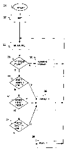
Figure 2 illustrates a flow chart for a method for controlling a warning
signal in an
apparatus for monitoring the autonomous nervous system of a sedated patient,
and
especially for detecting stress or discomfort and awakening.
The method starts at reference 31.
The first process step 32 is an initial step, establishing initial values for
use in the
remaining, repeated process steps.
In step 33, skin conductance signal or EDR (electrodermal response) signal is
measured, preferably in microsiemens (uS), time-quantized and converted to
digital
form using the equipment described with reference to fig. 1. A time-series of
a
certain duration, typically between 5 seconds and 40 seconds, and more
preferably
between 5 and 20 seconds, e.g. about 15 seconds, containing skin conductance
data,
CA 02597004 2007-08-03
WO 2006/083178 PCT/N02006/000049
6
is acquired during this step. At 15 seconds, with a sampling rate of 20 ¨ 200
samples per second, the time-series may contain 300 ¨ 3000 samples.
In the test step 35, a test is performed in order to detect the existence of
valid peaks
in the time-series of the acquired skin conductance signal. If more than one
peak is
detected, the process continues at step 40. If one or no peak is detected, the
process
continues at step 36.
In step 36, both output signals 71 or 72 are set to passive state. Thus, if
zero or one
valid peak has been detected in step 35, the first output signal 71 indicates
no
awakening, and the second output signal 72 indicates no pain in the patient.
The existence of a valid peak is established in step 35 if the derivative of
the signal
changes sign through a small period in the interval. The derivative of the
signal is
calculated as the difference between two subsequent sample values. In
addition, it is
possible to use a simple digital filter that needs to see two or more
subsequent sign
changes before the sign change is accepted.
In the test step 35 it may be necessary to establish additional criteria for
when a
peak should be considered as valid. In their simplest form such criteria may
be
based on the fact that the signal amplitude has to exceed an absolute limit in
order
to be able to be considered a valid fluctuation. A recommended, such reference
value for the conductance is between 0.01uS and 0.02 !IS, preferably 0.015 S.
Alternatively or in addition, it is an advantage to base the criteria on the
fact that
the signal actually has formed a peak that has lasted a certain time. The
criteria may
also be based on the fact that the increase in the skin conductance signal
value as a
function of time must remain below a certain limit, typically 20 uS/s, if the
maximum value is to be considered valid.
Another possible condition for establishing a valid peak is that the absolute
value of
the change in the conductance signal from a local peak to the following local
valley
exceeds a predetermined value, such as a value in the range [0.01uS, 0.02uS],
e.g.
0.015 S.
Also, a maximum value appearing at the border of the interval, i.e. the
starting point
or ending point of the interval should preferably not be regarded as a valid
peak.
CA 02597004 2007-08-03
WO 2006/083178 PCT/N02006/000049
7
The object is thereby achieved that artifacts, which can occur in error
situations
such as, e.g., electrodes working loose from the skin, or other sources of
noise or
disturbances, does not lead to the erroneously detection of peaks.
Step 40 is a test step wherein the amplitudes of fluctuation peaks in the skin
conductance signal through the time interval is considered. An average value
of the
amplitudes through the interval is calculated. If the calculated average value
exceeds a first limit value in the range [0,05 }IS, 0,20 S], preferably in
the range
[0,07 S, 0,13 S], or more preferably about 0,10 S, an awakening state in
the
patient is detected, and the process continues at step 39.
If the calculated average amplitude value does not exceed the first limit
value, the
process continues at step 41.
In step 41, the basal level of the skin conductance signal through said
interval is
considered. If the basal level has shown a recent significant increase, an
awakening
state in the patient is detected, and the process continues at step 39. More
particularly, this is the case if the basal level has increased more than a
second limit
value in the range [0,05 S, 0,3 S] during a recently elapsed time interval
in the
range [10 seconds, 30 seconds]. Preferably, the second limit value is within
the
range [0,08 S, 0,12 S] and the recently elapsed time interval is in the
range [12
seconds, 18 seconds]. For instance, the second limit value may advantageously
be
0,1 S and the elapsed time interval 15 seconds.
If the basal level has not shown such a significant increase, the process
continues at
step 37.
In step 37, the width of the pulses of the skin conductance signal is
calculated, and
the width is compared with a preset reference value. If the pulse width is
above the
reference value, this indicates that the patient is receiving awakening
stimuli and
may need more hypnotics, thus the process continues at step 39. If the pulse
width
is below the second reference value, this indicates a state of pain
pain/discomfort.
The process continues to step 38, where the output signal 72, indicating pain,
is set.
The process is then repeated from step 33.
CA 02597004 2007-08-03
WO 2006/083178 PCT/N02006/000049
8
The width of a pulse may be calculated as twice the time difference between
the
local minimum value and the local peak in one fluctuation The width may also
be
calculated as the time difference between the local minimum values in the skin
conductance signal. The width of a pulse may alternatively be calculated as
the time
difference between local peaks in the skin conductance signal. When several
pulses
are detected in the time series, the maximum width may advantageously be
stored
and used for the further processing. Another way of measuring the width of the
pulses is to count the number of pulses during the time interval and
calculating the
width as the length of the time interval divided by the number of pulses
during the
time interval. Even another way of measuring the width of the pulses is to
ensure
that, during the time period, at least more than one pulse has a width above a
preset
reference value. Then, the average pulse width is calculated, based on the
width of
the pulses with a width above the preset value.
The reference value of the pulse width should be within the rauge [1 second, 5
seconds]. In order to obtain even better and more reliable results, the
reference
value should be within the range [1,5 seconds, 3 seconds], e.g. about 2
seconds.
In step 39, the output signal 71 is set or activated. The process is then
repeated from
step 33.
The process may be interrupted or terminated by an operating device (not
shown) or
by a command input from the communication port 56.
An improvement to the method illustrated in figure 2 will be described in the
following:
In the embodiment in figure 2, a time-series is first acquired and
subsequently
analyzed. As an advantageous alternative, data acquisition and analysis are
performed as separate, independent processes, concurrently executed by the
processing unit 53.
A data acquisition process is then performed, which virtually continuously
updates
a portion of the memory 55 with the latest e.g. 15 seconds of skin conductance
signal values.
CA 02597004 2007-08-03
WO 2006/083178 PCT/N02006/000049
9
An analysis process is initiated e.g. every 1 second. This process will
analyze the
latest e.g. 15 seconds of skin conductance data, acquired by the concurrently
executed data acquisition process. All the process steps 33-39 are performed
by the
analysis process, while the initial process step 32 is performed in advance,
as initial
step.
This solution leads to an even faster and more reliable indication of
awakening,
compared to the simpler method described with reference to figure 2.
The invention has been primarily, described with reference to human patients.
It
should be appreciated that the invention also may be used with animals.