Note: Descriptions are shown in the official language in which they were submitted.
CA 02597285 2007-08-14
SHOE SOLE
BACKGROUND INFORMATION
[0001] FIELD OF THE INVENTION
[0002] The invention relates to the field of shoes. More particularly, the
invention relates to shoe soles.
[0003] DESCRIPTION OF THE PRIOR ART
[0004] The natural design of the foot enables a smooth rolling motion
throughout a step when walking. Studies of people's footprints in sand show
that
the foot rolls from heel to toe and, at the same time, also from an outside
slant
(supination) to an inside slant (pronation), in a smooth rolling motion. The
step
begins with setting the heel down on the walking surface and ends with the
large
toe pushing the foot off the walking surface. The toe at the end of the step
and
the heel at the beginning of the step are on the same plane. The center of
gravity of the person is applied forward of the ankle, so that, in a normal
standing
position, the greatest portion of body weight is borne by the front portion of
the
foot, i.e., the ball and toes, and not the heel.
[0005] Traditional shoe soles cancel much of this natural design. Most
traditional shoe soles are constructed with a heel portion that raises the
bottom
horizontal plane of the heel above the bottom horizontal plane of the ball of
the
foot and toes. This orientation of the foot distorts the natural interaction
of certain
foot joints and ligaments and results in chronic tension that leads to
inflammation
of various foot joints. With these traditional shoe soles, when the step
begins,
the heel is set down at an elevated level above the walking surface. The ball
of
the foot and the toes are at an unnatural angle relative to the heel and, as
the
1
CA 02597285 2007-08-14
foot moves through the step, the ball of the foot drops, rather than rolls,
onto the
walking surface. The joints and ligaments are not in their natural and
intended
orientations and, as a result, the toe cannot push the foot away from the
walking
surface naturally. The raised heel portion forces the center of gravity of the
body
off-center, back toward the ankle and heel. Too much weight is placed on the
heel. This overloads certain joints in the foot and causes bone spurs and
other
problems in the heel. The shift in the center of gravity also typically causes
misalignment of the knees and of the hips. Many of the muscles intended to be
used in walking are not used properly and, as a result, atrophy from lack of
use.
This chronic misalignment of the foot during walking leads to foot fatigue and
the
development of chronic postural problems, with the result that many people
complain of problems with their feet, ankles, knees, and even lower spine.
[0006] Traditional shoe soles also inhibit the natural rolling motion from the
outside edge to the inside edge of the foot as it goes through the step
motion.
Traditional shoe soles flex only along lines that run transverse to the
longitudinal
direction of the shoe sole, and are typically constructed to prevent flexure
in the
longitudinal direction, that is, they do not flex along longitudinal lines,
from the
outer side to the inner side of the foot.
[0007] Many efforts have been made over the years to construct a shoe sole
that promotes a healthy and natural walking gait, alleviates foot pain, and
does
not cause fatigue. Some shoe soles have a negative heel portion. This type of
sole creates tension in other parts of the foot and lower spine and does not
promote a natural gait. Some shoe soles are constructed with a tripartite
sole.
The middle portion of the tripartite sole presents a flat bottom surface. The
front
portion of the sole has a flat bottom surface that is angled upward relative
to the
middle portion. The rear portion of the sole also has a flat bottom surface
that is
also angled upward, relative to the middle portion, but at a lesser angle than
that
2
CA 02597285 2007-08-14
of the front portion. The upper surface of the sole is flat, from heel to toe.
Thus,
the sole does not support the arch or the toes. The tripartite lower surface
causes an abrupt rocking motion through the step and also requires that the
wearer have a good sense of balance.
[0008] Conventional shoe soles have a flat upper surface. A formed insole is
the placed on top of the shoe sole. This insole is typically made of a soft,
cushioning material, and does not provide the even, continuous support along
the bottom of the foot that is needed when walking.
[0009] What is needed, therefore, is a shoe sole that allows the foot to roll
naturally from heel to toe and side to side. What is further needed is such a
shoe
sole that supports the entire foot throughout the entire step.
BRIEF SUMMARY OF THE INVENTION
[0010] The invention is a shoe sole with a rocker or roller bottom that is a
continuously curved bottom surface. The shoe sole has a bottom surface that
contacts the walking surface and an upper surface that contacts the foot of
the
wearer. The continuous curve curves downward from the heel section through a
mid-section that presents the lowest point of the continuous curve, and then
upward to the toe section. The angle of curvature is not the same throughout
the
sole. Rather, the angle of curvature of the heel portion, relative to the
curvature
of the mid-section, is greater than the angle of curvature of the toe-section.
Also
formed in the lower surface is a longitudinal flex groove that allows the shoe
sole
to flex along lines that extend in the longitudinal direction of the shoe
sole,
thereby allowing the foot to roll naturally from side to side simultaneously
as it
rolls from the heel toward the first toe.
3
CA 02597285 2007-08-14
[0011] The upper surface of the shoe sole is a multi-planed formed surface
that supports the entire bottom of the foot and maintains the foot in proper
alignment, while allowing the foot to roll naturally from side to side and
from heel
to toe throughout the step motion. The upper surface has a heel section, an
arch
section, a ball section, and a toe section. The arch section rises above the
level
of other areas on the upper surface and supports the arch throughout the
entire
step. The ball section has a depression that cradles the ball of the foot. The
toe
area aligns the toes properly, particularly the first toe, so that it is in
proper
position to push the foot away from the walking surface.
BRIEF DESCRIPTION OF THE DRAWINGS
[0012] The present invention is described with reference to the accompanying
drawings. In the drawings, like reference numbers indicate identical or
functionally similar elements.
[0013] FIG. 1 illustrates the shifting of the center of gravity along the foot
when walking barefoot on sand.
[0014] FIG. 2 is a plane view of the upper surface of the shoe sole.
[0015] FIG. 3 is a plane view of the bottom surface of the shoe sole.
[0016] FIG. 4 is a side plane view of the shoe sole, from the inner side,
showing two different curvatures on the front and rear portions of the shoe
sole,
and the ball depression in the front portion.
[0017] FIG. 5 is a transverse slice of the shoe sole across the rear heel
area.
[0018] FIG. 6 is a transverse slice of the shoe sole across the mid-heel area.
4
CA 02597285 2007-08-14
[0019] FIG. 7 is a transverse slice of the shoe sole across the arch area.
[0020] FIG. 8 is a transverse slice of the shoe sole across the front of the
sole, just behind the ball area.
[0021] FIG. 9 is a transverse slice of the shoe sole across the ball area
[0022] FIG. 10 is a transverse slice of the shoe sole across the toe area.
[0023] FIG. 11 illustrates the how the body weight is applied to the bottom
surface of the foot, when walking barefoot on sand.
[0024] FIG. 12 shows the longitudinal flex groove under no-load condition.
[0025] FIG. 13 shows the longitudinal flex groove flexing under load
condition.
[0026] FIG. 14 shows the curvature of the sole, without the weight of the body
applied to the foot.
[0027] FIG. 15 shows the flattening of the sole and the increased support for
the arch when body weight is applied to the foot.
DETAILED DESCRIPTION OF THE INVENTION
[0028] The present invention will now be described more fully in detail with
reference to the accompanying drawings, in which the preferred embodiment of
the invention is shown. This invention should not, however, be construed as
limited to the embodiment set forth herein; rather, the drawings are provided
so
that this disclosure will be complete and will fully convey the scope of the
invention to those skilled in the art.
CA 02597285 2007-08-14
[0029] FIGS. 12 and 1 illustrate the natural motion of the foot through a
complete walking step, from 12A through 12D. The upper portion of FIG. 12
shows a foot going through the walking step; the lower portion shows how the
body weight is shifted along the sole of the foot. The areas A through D in
FIG.
12 correspond to the similarly marked areas in FIG. 1. The shift in center of
gravity is illustrated generally by line L in FIG. 1. The foot first comes
into
contact with a walking surface at 1 and rolls in a forward direction from heel
A at
1 to toe D at 4, where the foot pushes away from the walking surface. The foot
also rolls simultaneously from side to side. Initially, the foot rolls
outward, shifting
the weight from the heel A toward the outer lateral side B. Then, as the back
of
the foot lifts away from the walking surface, the toes D turn down and the
foot
rolls over to the inner side, shifting the weight onto the ball area C. In the
final
phase of the step, the kicking off phase, the foot bends at the toes and the
weight
is shifted primarily onto the first toe D at 4, at which point the toe pushes
the foot
away from the walking surface. This forward and side-rolling motion is the
natural motion for a barefoot person walking on a surface such as sand. The
shoe sole 100 of the present invention emulates and promotes this same natural
forward and side-rolling motion.
[0030] FIGS. 2-11 illustrate a shoe sole 100 according to the invention. In
the preferred embodiment, the shoe sole 100 is a single-shot injection molded
sole, although it is understood that it may also be made as a double-shot
injection molded sole. FIG. 2 shows an upper surface 200, FIG. 3 a lower
surface 300, and FIG. 4 shows a side view of the shoe sole 100. FIGS. 5-10
show transverse slices of the shoe sole 100, which illustrate the various
features
and contours at different locations on the sole. The shoe sole 100 has a toe
area
110, a heel area 120, an arch area 130, a outer side 140, an inner side 150,
and
6
CA 02597285 2007-08-14
a ball area 160. Directional arrows X and Y indicate a transverse direction or
orientation and a longitudinal direction or orientation, respectively.
[0031] Referring now particularly to FIG. 2: The upper surface 200 has a first
flex zone 210 in the ball area 150 for increasing the ability of the shoe sole
100 to
flex in this area in the transverse direction. In the embodiment shown, the
flex
zone 210 is defined by a series of transverse grooves. A second flex zone 220
is
formed in the heel area. This second flex zone 220 reduces the weight of the
shoe sole 100, as well as increases the ability of the sole 100 to flex, both
in the
transverse direction X and in the longitudinal direction Y. Depending on the
size
of the particular shoe sole or the body weight of the intended wearer, it is
understood that the flex zones 210 and 220 may be adapted to provide greater
or
lesser flex. A recess 222, best seen in FIGS. 6 and 7, is also formed
centrally
along the heel area 120 for receiving a reinforcing bar. An arch support 230
is
formed on the inner side 130, which supports the arch throughout the walking
step and holds the foot in a slightly supinated position, that is, oriented
toward
the outer side 140, for the first half of the step. A side wall 400 that is
adapted to
attach to an upper shoe rises from and encircles the upper surface 200.
[0032] FIG. 2 further illustrates a flat area 260 delineated with hatch lines
and
a ball depression 250 formed in the ball area 150. The flat area 260 is a
plane
surface and the ball depression 250 cradles the ball of the foot. The flat
area 260
includes the heel area 120 and the outer side 140. The arch area 130 is raised
relative to the flat area 260. The lower plane of the ball depression 250 is
lower
than the plane of the flat area 260. The plane of the toe area 110 is raised,
relative to the lower plane of the ball depression 250. Together, the ball
depression 250 and the flat area 260 bed the foot in a way that accommodates
the natural curve of the foot of a barefoot person standing on sand, and also
stabilize the balance of the person while standing still. Thus, although the
lower
7
CA 02597285 2007-08-14
surface 300 is continuously curved, the upper surface 200 provides a stable
bed
for the foot, so that the wearer does not have to continually seek a balance
point
or balance on the toes, when standing still.
[0033] Referring now particularly to FIG. 3: Traction pads 310 are formed
along the lower surface 300, separated by transverse flex grooves 320. The
transverse flex grooves 320 vary in size and shape and are constructed to
control the amount of flex in the heel, ball, and toe areas 120, 150, and 110.
A
longitudinal flex groove 330 extends through the arch section 130 into the
heel
section 120 and controls the amount of side-to-side flex in the arch area 130.
The longitudinal flex groove 330 extends from the arch section 130 to an
inside
area of the heel section 120. This longitudinal flex groove 330 promotes
flexing
of the shoe sole 100 in the longitudinal direction Y, to accommodate a shift
in
body weight from the outer lateral side B of the foot to the first toe D. See
also
FIGS. 12 and 13, which illustrate the flexing of the shoe sole 100 as the foot
rolls
from the outer side 140 to the inner side 150. This shift in body weight
occurs in
a natural walking gait of a barefoot person walking on a sand, for example,
and is
prevented by conventional shoes, which allow the sole to flex in the
transverse
direction only.
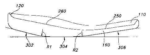
[0034] FIG. 4 is a side view of the inner side 150 and outer side 140 of the
shoe sole 100 and particularly illustrate that the lower surface 300 is an
irregularly, yet continuously curved surface. A first curve 302 in the heel
area
120 has a radius of curvature greater than that of a second curve 306 in the
ball
and toe areas 160 and 110. A transition curve 304 in the arch area 130 is a
continuous curve that transitions from the first curve 302 to the second curve
302. In the embodiment shown, the first curve 302 has a radius R1 of
291.22 mm and the second curve 306 a radius R2 of 710.51 mm, whereby the
radius R7 is preferably a minimum of 272.0 mm. These radii were selected,
8
CA 02597285 2007-08-14
because they provide a stable comfortable walking posture for the average
person. Other suitable radii of curvature may be selected, as long as they
provide a stable and comfortable walking posture.
[0035] FIG. 5 shows a transverse slice across the very rear section of the
shoe sole; FIG. 6 shows a transverse slice across the middle section of the
heel
area 120. The outer side 140 of the upper surface 200 is slightly lower than
the
inner side 150, to promote a roll of the foot to the outer side during the
first half of
the step motion, that is, when the heel is placed on the walking surface. A
recess 222 is provided for a reinforcing bar 222A. The arch area 130
compresses somewhat, depending on the weight of the person. The reinforcing
bar 222A prevents this compression from deforming the flat area 260 that runs
parallel to both sides of the reinforcing bar 222A and ensures that the shoe
sole
100 applies even pressure to the bottom of the foot.
[0036] FIG. 7 shows a transverse slice across the arch area 130, illustrating
an arch support 230 that is noticeably raised above the level of the outer
side
140.
[0037] FIG. 8 shows a transverse slice across of the ball area 160,
illustrating
the ball depression 250. The inner side 140 is now very close to the same
level
of the outer side 140. When the foot rolls naturally from the heel onto the
ball, it
also rolls sideways into pronation, placing more of the body weight on the
ball of
the foot just behind the first toe. The ball depression 250 promotes this side-
to-
side roll and also keeps the ball of the foot and the toes from slipping in
the
transverse or longitudinal direction.
[0038] FIGS. 9 and 10 show transverse slices of the shoe sole across the
front portion of the ball area 150 and the toe area 110, respectively. The
ball
9
CA 02597285 2007-08-14
depression 250 serves to hold the foot in a naturally curved orientation, with
the
ball of the foot in a lower plane than the toes and the arch. This ensures
proper
weight distribution in several ways. First, the arch of the foot remains in
contact
with the shoe sole over a greater area, effectively distributing the body
weight
evenly over the ball and arch areas. At the same time, the ball depression 250
increases the stability of the foot by bedding the ball area on a slightly
lower
plane, relative to the rest of the foot. Finally, the higher plane of the toe
area
110, relative to the plane of the ball depression 250, raises the toes
slightly,
positioning them in a natural position to better to push the foot off against
the
walking surface.
[0039] FIGS. 12 and 13 illustrate how the shoe sole 100 flexes in the
longitudinal direction to allow the fool to roll from the outer side 140 to
the inner
side 150. FIG. 12 shows the upper surface 200, which is designated as 200A in
this figure, in the area above the longitudinal flex groove 330. The upper
surface
200A is flat, reflecting the condition of the shoe sole 100 when no weight is
applied to the upper surface 200 of the shoe sole. FIG. 13 shows the shoe sole
100 with weight applied to the upper surface, also in the area above the
longitudinal flex groove 330, which is designated in this figure as 200B. The
upper surface 200B is tilted downward slightly, because the longitudinal flex
groove 330 has allowed the shoe sole 100 to flex as the center of gravity of
body
weight shifts from the outer side 140 to the inner side 150. The upper surface
200A/200B coincides in part with the flat area 260 with the reinforcing bar
222A
shown in FIGS. 6 and 7. The reinforcing bar 222A prevents the flat area 260
from buckling in a transverse direction X or overflexing, yet allows the area
that
runs parallel to the reinforcing bar 222A to drop off slightly in the
longitudinal
direction Y, to accommodate the roll of the foot from side to side. This
interaction
between the reinforcing bar 222A and the longitudinal flex groove 330 provides
a
CA 02597285 2007-08-14
continuous support on the foot and promotes good balance. The reinforcing bar
222A is constructed to allow this slight longitudinal flexing on the upper
surface
200 and is adapted to the approximate weight of the intended wearer of the
shoe.
Shoes intended to be worn by persons weighing 120 or more, for example, may
be made of metal, whereas shoes intended to be worn by children or other
persons weighing less than 120 may be made of fiberglass. It is envisioned
that
a person acquiring a pair of shoes having the shoe sole 100 according to the
invention will specify which type of reinforcing bar is desired.
[0040] FIGS. 14 and 15 are side cut-away views of the shoe sole 100,
showing the upper surface 200 and the lower surface 300 in profile from the
inner
side 150. In FIG. 14 illustrates the curvature of the shoe sole 100 under no-
load
condition. As shown, the foot is resting in the shoe, with the arch of the
foot
naturally curved. No weight is applied to the arch of the foot at this time,
that is,
the foot is not bearing down on the upper surface 200. The lower surface 200
of
the sole 100 is curved to its fullest extent, as shown by distances Dl HEEL
and
D1TOE. In FIG. 15, the weight of the body is applied to the shoe sole 100. The
sole 100 flexes in the transverse direction in the area about the arch support
230,
with the result that the lower surface 300 flattens out, as shown by distances
D2HEEL and D2TOE and the upper surface 200 flexes upward into the foot,
applying pressure evenly, thereby balancing the weight along the large bones
in
the foot, which are designed to carry the weight. The shoe sole 100 is now
providing positive support for the entire surface of the foot: the heel, the
arch, the
ball and the toe areas.
[0041] It is understood that the embodiments described herein are merely
illustrative of the present invention. Variations in the construction of the
shoe
sole may be contemplated by one skilled in the art without limiting the
intended
scope of the invention herein disclosed and as defined by the following
claims.
11