Note: Descriptions are shown in the official language in which they were submitted.
CA 02597547 2007-08-15
-1-
TIRE ADNIINISTRATION SYSTEM
TECHNICAL FIELD
[0001] The present invention relates to improvement in a tire administration
system
including a sensor module that is secured to an inner side of a tire mounted
on a vehicle,
for measuring a tire state quantity inclusive of a tire inner pressure, and a
receiver module
secured to a vehicle body side, for receiving the measured data transmitted
from the
sensor module.
BACKGROUND ART
[0002] For performing administration of tires under operation of construction
vehicles
or the like, there has been proposed to mount a tire administration system on
a vehicle,
wherein a sensor module for measuring a tire state quantity, such as an inner
pressure or
temperature of the tire, is secured to an inner side of the tire, the measured
data from the
sensor module is received by a receiver module on the vehicle body side, and
the received
data is transmitted to a vehicle operation administration center where the
operation of a
plurality of vehicles is administered. This proposal has for its object to
ensure that, if it
is judged, based on the data of the tire administration system provided for
each vehicle,
that the vehicle is likely to cause a failure, then a necessary command is
given to the
driver from the vehicle operation administration center so as to avoid a
dangerous
situation in advance. Refer, for example, to Patent Document 1 identified
below.
[0003] Such a tire administration system is configured so that the data
request signal is
transmitted form each receiver module to the corresponding sensor module at a
predetermined period, and the sensor module measures the tire state quantity
in
accordance with the reception timing of the data request signal and transmits
the
measured data to the receiver module, thereby allowing the receiver module to
acquire the
measured data fro the sensor module.
- Patent Document 1: Japanese Patent Application Laid-open Publication No. 10-
104103
DISCLOSURE OF THE INVENTION
(Task to be Solved by the Invention)
[0004] In the above-mentioned tire administration system, the electric field
intensity at
the location of the sensor module is small due to the shielding effect of the
steel belt that
constitutes the tire. Moreover, at the signal reception section of the sensor
module, in
order to suppress exhaustion of batteries for driving the sensor module, the
signal
reception sensitivity is at low level. Therefore, the signal intensity of the
data request
CA 02597547 2007-08-15
-2-
signal transmitted from each receiver module to the sensor module is
correspondingly
increased. However, from the viewpoint of interference to other electronic
appliances
when the signal transmitted from a wireless device has a high intensity, some
countries
pose a restriction for a continuous transmission of wireless signal at an
intensity above a
predetermined level and at the same frequency. In such countries, there may be
instances wherein the frequency of the data request signal transmitted from
the receiver
module to the sensor module must be periodically changed.
[0005] However, due to influences from other vehicles or disturbances,
depending upon
the frequency of the data request signal, the reception probability of the
data request
signal at the sensor module may be extremely low. In such an instance, since
the data
request signal cannot be received by the sensor module, it is necessary for
the receiver
module to transmit the data request signal while successively changing the
frequency
until the sensor module is able to receive the data request signal, thereby
giving rise to a
problem that it takes long time until the measured data is acquired from the
sensor
module.
[0006] The present invention has been achieved in view of suclf a problem. It
is a
primary object of the present invention to provide a tire administration
system capable of
selecting a frequency of a high reception probability, when a measured data
request signal
is transmitted from a receiver module to a sensor module, or when a frequency
of the data
request signal is changed, so as to promptly acquire a measured data from the
sensor
module.
(Means for Solving the Task)
[0007] To this end, a first aspect of the present invention resides in a tire
administration
system comprising: a sensor module secured to an inner side of a tire mounted
on a
vehicle, for measuring a tire state quantity and transmitting a measured data
to a vehicle
body side; and a receiver module secured to the vehicle body side, for
transmitting a data
request signal at a predetermined period so as to request said measured data
to said sensor
module, and for receiving the measured data transmitted from said sensor
module;
wherein said receiver module is configured so as to (i) transmit said data
request signal to
said sensor module at a frequency used for a latest, successful acquisition of
said
measured data, (ii) transmit said data request signal to said sensor module if
said
measured data cannot be acquired, repeatedly until said measured data is
acquired, and
(iii) transmit said data request signal to said sensor module, if the number
of transmission
of said data request signal reached a designated number of transmission, at a
frequency
CA 02597547 2007-08-15
-3-
used for a second latest, successful acquisition of the measured data.
[0008] In this instance, it is preferred that said receiver module is
configured to transmit
said data request signal to said sensor module by (i) designating the
frequency with which
said latest acquisition of said measured data was successful, as a frequency
of a measured
data signal, if said data request signal is transmitted with a frequency used
for said latest,
successful acquisition of the measured data, and (ii) designating the
frequency used for
said second latest, successful acquisition of said measured data, as the
frequency of the
measured data signal, if said data request signal is transmitted with a
frequency used for
said second latest, successful acquisition of the measured data.
[0009] A second aspect of the present invention resides in a tire
administration system
comprising a sensor module secured to an inner side of a tire mounted on a
vehicle, for
measuring a tire state quantity and transmitting a measured data to a vehicle
body side;
and a receiver module secured to the vehicle body side, for transmitting a
data request
signal at a predetermined period so as to request said measured data to said
sensor module,
and for receiving the measured data transmitted from said sensor module;
wherein said
receiver module is configured so as to (i) transmit said data request signal
to said sensor
module at a frequency used for a latest, successful acquisition of said
measured data, (ii)
transmit said data request signal to said sensor module, if said measured data
cannot be
acquired, repeatedly until said measured data is acquired, and (iii) transmit
said data
request signal to said sensor module, if the number of transmission of said
data request
signal reached a designated number of transmission, at a frequency of one
channel among
both channels adjacent to a channel of a frequency used for a second latest,
successful
acquisition of the measured data was successful.
[0010] A third aspect of the present invention resides in a tire
administration system
comprising: a sensor module secured to an inner side of a tire mounted on a
vehicle, for
measuring a tire state quantity and transmitting a measured data to a vehicle
body side;
and a receiver module secured to the vehicle body side, for transmitting a
data request
signal at a predetermined period so as to request said measured data to said
sensor module,
and for receiving the measured data transmitted from said sensor module;
wherein said
receiver module is configured so as to (i) transmit said data request signal
to said sensor
module at a frequency of a channel of a first highest reception probability
for the
measured data, (ii) transmit said data request signal to said sensor module if
said
measured data cannot be acquired, repeatedly until said measured data is
acquired, and
(iii) transmit said data request signal to said sensor module, if the number
of transmission
CA 02597547 2007-08-15
-4-
of said data request signal reached a designated number of transmission, at a
frequency of
a channel of a second highest reception probability for the measured data.
(Effects of the Invention)
[0011] With the tire administration system according to the present invention,
the
receiver module transmits the data request signal to the sensor module by
selecting a
frequency with a high reception probability, transmits the data request signal
if the
measured data cannot be acquired, repeatedly until the measured data is
acquired, and
transmits the data request signal, if the number of transmission of the data
request signal
reached a designated number of transmission and the data request signal has
thus to be
transmitted to the sensor module with a different frequency, by selecting a
frequency with
as higher reception probability as possible. In this way, it is possible to
promptly acquire
the measured data from the sensor module.
BRIEF DESCRIPTION OF THE DRAWINGS
[0012] FICx 1 is a view schematically showing the arrangement of the tire
administration
system according to the present invention;
FIGS. 2(a) and 2(b) are timing charts showing an example of signal output from
the sensor module and the receiver module;
FIG 3 is a timing chart showing the data request signal in enlarged scale;
FICx 4 is a conceptual view showing the frequency ranges as used for data
transmission by the receiver module and the sensor module, respectively;
FIGS. 5(a) and 5(b) are conceptual views showing the structure of the data
transmitted by the receiver module and the sensor module, respectively; and
FICx 6 is a flow chart showing the data processing of the receiver module.
BEST MODE FOR CARRYING OUT THE INVENTION
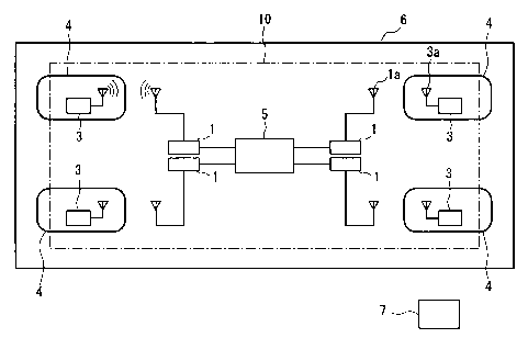
[0013] The present invention will be described below with reference to the
embodiments shown in the accompanying drawings. FIG 1 schematically shows the
arrangement of the tire administration system according to the present
invention. The
tire administration system 10 is comprised of a sensor module 3 secured to an
inner side
of a tire 4 that is mounted on a vehicle 6, for measuring a tire state
quantity, a receiver
module 1 provided for a vehicle body side, for transmitting a data request
signal at a
predetermined period so as to request the measured data to the sensor module
3, and
acquiring the measured data transmitted from the sensor module 3, and a
central control
module 5 providing command to the receiver module 1 to acquire data from the
sensor
module 3.
CA 02597547 2007-08-15
-5-
[0014] The sensor module 3 is secured to the inner surface of the tire 4 by
baking, in
order that it is prevented from separation from the tire or breakage even when
the tire
undergoes deformation in its running state under a loaded condition.
Furthermore, the
sensor module 3 is comprised of a detector means for detecting tire inner
pressure or the
like, an antenna 3a and a transmitter for the transmission and reception to or
from the
receiver module 1, and a controller means for controlling these elements. The
detector
means may include a detector for detecting the tire temperature besides the
tire inner
pressure. Incidentally, the sensor module 3 may be secured to a road wheel
within the
tire interior space, or may be held within the tire interior space by a
separate holder
means.
[0015] The receiver module 1 is comprised of an antenna la for receiving a
wireless
signal from the sensor module 3 including a measured data of the temperature
or pressure,
and acquires the measured data of the temperature or pressure from the antenna
la. The
receiver module 1 may be arranged inside of the central control module 5. The
central
control module 5 performs a wireless transmission of the measured data
obtained by the
receiver module 1 to a vehicle operation administration center 7, which
receives the
signal from the central control module 5 to monitor the running state of the
tires.
[0016] FIG 2(a) is a timing chart of the data request signal transmitted by
the sensor
module 3 to the receiver module 1. The data request signal D is transmitted to
the
sensor module 3 at a predetermined period T, and the transmission of the data
request
signal is repeated at a time interval of the period T.
[0017] FIG 2(b) is a timing chart of the measured data transmitted from the
sensor
module 3 to the receiver module 1. Upon detection of the data request signal D
transmitted from the receiver module at the time interval of the period T, the
sensor
module 3 measures the tire state quantity such as tire inner pressure, and
transmits the
measured data signal A as the measurement result to the receiver module 1, via
the
antennas la and 3a.
[0018] FICx 3. As shown in FICx 3, which is a timing chart of the data request
signal in
enlarged scale, the data request signal D transmitted by the receiver module 1
is
comprised of a plurality of data request signals E that are transmitted at a
predetermined
period. If there is no data transmission from the sensor module within a
predetermined
time, in response to the data request signal E transmitted at a frequency Fl,
the receiver
module 1 transmits the data request signal E again and wait for the data
transmission from
the sensor module 3. Furthermore, if there is no data transmission from the
sensor
CA 02597547 2007-08-15
-6-
module 3, even after repeated transmission of the data request signal E until
a designated
number m of transmission (m=4, in FIC~ 3) designated for the data request
signal E has
been reached, the receiver module 1 transmits the data request signal E at a
different
frequency F2 and wait for the data transmission from the sensor module 3. The
transmission of the data request signal E is stopped once the data
transmission from the
sensor module 3 has been confirmed. Accordingly, the number of data request
signals E
changes depending upon the presence or absence of the data transmission from
the sensor
module 3.
[0019] FICx 4 is a conceptual view showing the frequency ranges as used for
data
transmission by the receiver module 1 and the sensor module 3, respectively,
wherein the
abscissa represents the frequency. The frequency ranges as used by the
receiver module
1 and the sensor module 3 for transmission are determined by dividing the
predetermined
frequency range AF as shown, so that they do not overlap with each other. In
the
illustrated embodiment, fifty three (53) channels indicated by RM are assigned
to the
transmission of the data request signal from the receiver module 1 to the
sensor module 3,
and fourteen (14) channels are assigned to the transmission of the measured
data from the
sensor module 3 to the receiver module 1.
[0020] The identification code of the channel as used by the sensor module 3
for the
transmission of the measured data is transmitted to the sensor module 3 as a
part of the
data request signal to be transmitted by the receiver module 1. Upon receipt
of this
signal, the sensor module 3 transmits the measured data signal by using the
frequency of
the channel designated therein.
[0021] FIC~ 5(a) shows the data structure of the data request signal that is
transmitted by the receiver module. Besides a command CMD and an
autoidentification
code ID of the sensor module 3 to which the transmission is to be effected,
the data
request signal is comprised of an identification code f identifying the
channel to be used
by the sensor module 3 for the transmission of the measured data signal, as
mentioned
above. On the other hand, FIG 5(b) shows the structure of the measured data
signal
transmitted by the sensor module. The measured data signal is comprised of a
measured
data DATA, abnormal flag OK/NG and an identification code II) of the sensor
module 3
that performs the transmission.
[0022] In the next place, the operation of the receiver module will be
explained in detail.
FIG 6 is a flow chart showing the data processing of the receiver module 1,
wherein Fo,
Fl, F2 and F3 denote the frequencies of the data request signals transmitted
from the
CA 02597547 2007-08-15
-7-
receiver module 1 to the sensor module 3.
[0023] In step S1, the receiver module 3 judges whether the time of the period
T has
elapsed from the latest transmission of the data request signal to the sensor
module 1. If
the time of the period T has not elapsed, then step sl is repeated until the
period T has
elapsed. Once the period T has elapsed, counters nl, n2, and n3 for counting
the number
of transmission of the data request signals at frequencies Fl (Fo), F2 and F3
are set to 1,
respectively (step S2).
[0024] In next step S3, it is judged as to whether or not the counter nl is m
or less,
wherein m is a designated number of transmission as designated for the data
request
signal. In this instance, since the counter nl has been set to 1 and is thus
not more than
m, it is judged in step S4 as to whether or not there is a stored data of the
frequency Fl of
the data request signal, with which the latest measured data acquisition has
been
successful. If there is no such stored data, then the frequency of the data
request signal
is set to the frequency Fo according to the initial setting (step S5).
However, if there is a
stored data, then the frequency of the data request signal is set to the
stored frequency Fl
(step S6).
[0025] Subsequently, in step S7, the counter n1 representing the number of
transmission
of the data request signal is increased by 1. In next step S8, the receiver
module 1
designates the channel according to the initial setting, as the channel to be
used for the
transmission of the measured data signal, if the frequency of the data request
signal has
been set to Fo in step S5, and then transmits the data request signal at the
frequency Fo to
the sensor module 3, and designates the channel used for the latest successful
measured
data acquisition, as the channel to be used for the transmission of the
measured data signal,
if the frequency of the data request signal has been set to Fl in step S6, and
then transmits
the data request signal at the frequency Fl to the sensor module 3.
[0026] In next step S9, it is judged as to whether or not the receiver module
1 has
successfully acquired the measured data from the sensor module 3. If the
measured data
acquisition has been successful, then the frequency data of the frequency Fl
of the data
request signal and the data of the identification code of the channel to be
used by the
sensor module for the transmission of the measured data signal are stored
(step S10), the
measured data acquired from the sensor module 3 is stored (step S11), and the
processing
is then returned to step Si.
[0027] In step S9, if the measured data acquisition has been unsuccessful,
then the
processing is returned to step S3, where it is judged as to whether or not the
counter nl is
CA 02597547 2007-08-15
-8-
m or less. If the counter nl is m or less, then the frequency of the data
request signal is
set to the frequency Fl (FO) (steps S4, S5 and S6), and the counter nl is
increased by 1
(step S7) and the data request signal is transmitted to the sensor module 3 at
the frequency
Fl (FO).
[0028] In step S9, if the measured data acquisition has been unsuccessful
again, then the
processing is returned to step S3, where it is judged as to whether or not the
counter nl is
m or less. If the receiver module 1 repeats failure in acquiring the measured
data from
the sensor module 3, and the counter nl representing the number of
transmission of the
data request signal exceeds the designated number of transmission m of the
data request
signal, then the processing proceeds to step S12, where it is judged as to
whether or not he
counter n2 is m or less. In this instance, since the counter n2 has been set
to 1 and is thus
not more than m, if, for example, the frequencies of the data request signal
as used for the
previous successful acquisition of the measured data are stored as archival
record, then
the frequency of the data request signal is set to frequency F2 which has been
used for a
second latest, successful acquisition of the measured data (step S13).
[0029] In next step S14, the counter n2 representing the number of
transmission of the
data request signal is increased by 1. In step S8, the receiver module 1
designates a
channel that has been used for a second latest, successful acquisition of the
measured data,
as the channel to be used by the sensor module 3 for the transmission of the
measured
data, and transmits the data request signal at the frequency of F2. In step
S9, if the
acquisition of the measured data from the sensor module 3 is still
unsuccessful, the
processing is returned to step S3. In this instance, since the counter nl is
larger than m,
the processing proceeds to step S12, where it is judged as to whether or not
the counter n2
is m or less. If the counter n2 is m or less, then the frequency of the data
request signal is
set to F2 once again (step S13), the counter n2 is increased by 1 (step S14),
and the data
request signal is transmitted to the sensor module 3 at the frequency of F2.
(step S8).
[0030] In step S9, if acquisition of the measured data from the sensor module
3 is still
unsuccessful, the processing is retumed to step S3. In this instance, since
the counter n2
is larger than m, the processing proceeds to step S12, where it is judged as
to whether or
not the counter n2 is m or less. If the receiver module 1 still fails to
acquire the
measured data from the sensor module 1, and the counter n2 representing the
number of
transmission of the data request signal is larger than the designated number
of
transmission for the data request signal, then the processing proceeds to step
S15, where it
is judged as to whether or not the counter n3 is m or less. In this instance,
since the
CA 02597547 2007-08-15
-9-
counter n3 has been set in step S2 to 1 and is thus not more than m, if, for
example, the
frequencies of the data request signal as used for the previous successful
acquisition of the
measured data are stored as archival record, then the frequency of the data
request signal
is set to frequency F2 which has been used for a third latest, successful
acquisition of the
measured data (step S16).
[0031] In next step S17, the counter n3 representing the number of
transmission of the
data request signal is increased by 1. In step S8, the receiver module 1
designates the
identification code of a channel that has been used for a third latest,
successful acquisition
of the measured data, as the channel to be used by the sensor module 3 for the
transmission of the measured data, and transmits the data request signal at
the frequency
of F3.
[0032] In step S9, if the acquisition of the measured data from the sensor
module 3 is
still unsuccessful, the processing is returned to step S3. In this instance,
since the
counter nl is larger than m, the processing proceeds to step S12. Here, since
the counter
n2 is larger than m, the processing proceeds to step S15, where it is judged
as to whether
or not the counter n3 is m or less. If the counter n3 is m or less, then the
frequency of the
data request signal is set to F3 (step S16), the counter n3 is increased by 1
(step S17), and
the data request signal is transmitted to the sensor module 3 at the frequency
of F3. (step
S8).
[0033] In step S9, if the acquisition of the measured data from the sensor
module 3 is
still unsuccessful, the processing is returned to step S3. In this instance,
since the
counter nl is larger than m, the processing proceeds to step S12. Here, since
the counter
n2 is larger than m, the processing proceeds to step S15, where it is judged
as to whether
or not the counter n3 is m or less. If the receiver module 1 repeats failure
to acquire the
measure data from the sensor module 3, and the counter n3 representing the
number of
transmission of the data request signal is larger than the designated number m
of
transmission for the data request signal, then the processing is returned to
step S1.
[0034] In the above-described embodiment, when the receiver module 1 fails to
acquire
the measured data, the data request signal is transmitted to the sensor module
m times for
each of the different frequencies Fl (Fo), F2 and F3, before a continuous
transmission of
the data request signal is stopped. However, the continuous transmission of
the data
request signal may be continued by changing the frequency for each m times
further
transmission. Alternatively, the continuous transmission of the data request
signal may
be continued by returning to the initial frequency Fl (Fo) and sequentially to
F2 and F3.
CA 02597547 2007-08-15
-10-
[0035] In the above-described embodiment, furthermore, the frequency used for
the
latest, successful acquisition of the data signal is used as the frequency Fl
of the data
request signal, the frequency used for the second latest, successful
acquisition of the data
signal is used as the frequency F2, and the frequency used for the third
latest, successful
acquisition of the data signal is used as the frequency F3. However, it is
also possible to
use the frequency used for the latest, successful acquisition of the data
signal as the
frequency Fl, use the frequency of a channel having a high probability of the
data signal
acquisition, i.e., one channel among both channels adjacent to a channel of a
frequency
used for the latest, successful acquisition of the measured data as the
frequency F2, and
use the frequency of a channel having a high probability of the data signal
acquisition, i.e.,
another channel among both channels adjacent to a channel of a frequency used
for the
latest, successful acquisition of the measured data as the frequency F3. In
this instance,
the receiver module idesignates, as the channel to be used by the sensor
module 3 for
transmitting the measured data, the same channel as that designated for
transmitting the
data request signal at the frequency Fo or Fl, and transmits the data request
signal at the
frequency F2 or F3.
[0036] Further, it is also possible to derive the measured data acquisition
probability for
each of the fifty three (53) channels as shown in FIC~ 4, which have been
assigned for the
transmission of the data request signal from the receiver module 1 to the
sensor module 3,
and use the frequency of the channel with the highest reception probability as
the
frequency Fl, the frequency of the channel with the second highest reception
probability
as the frequency F2, and the frequency of the channel with the third highest
reception
probability as the frequency F3.
[0037] It will be appreciated from the foregoing description that, with the
tire
administration system according to the present invention, the receiver module
transmits
the data request signal to the sensor module by selecting a frequency with a
high
reception probability, transmits the data request signal if the measured data
cannot be
acquired, repeatedly until the measured data is acquired, and transmits the
data request
signal, if the number of transmission of the data request signal reached a
designated
number of transmission and the data request signal has thus to be transmitted
to the sensor
module with a different frequency, by selecting a frequency with as higher
reception
probability as possible. In this way, it is possible to promptly acquire the
measured data
from the sensor module.
CA 02597547 2007-08-15
-11-
INDUSTRIAL APPLICABILITY
[0038] The present invention is applicable to a system for performing a real-
time
measurement of the tire state information of not only construction vehicle
tires, but also
of all types of tires including passenger car tires.