Note: Descriptions are shown in the official language in which they were submitted.
CA 02597646 2007-08-13
-1-
Evacuation system having escape identification lights
1. Field of the Invention
The present invention relates to an evacuation system having escape
identification
lights, having monitoring sensors, and having a central computing system,
which
analyzes messages from the monitoring sensors and alternately releases or
blocks escape routes as a function thereof by targeted activation of building
de-
vices and escape identification lights.
2. Description of the Prior Art
In buildings, ships, or the like, it must always be ensured by providing
evacuation
systems of this type that spatial areas and/or zones may be left by a large
number
of individuals without danger within the shortest possible time. Static
signage may
possibly lead streams of individuals into the actual danger area, because no
tar-
geted escape route guiding may be performed. This not only results in delays
in
the evacuation, but rather may also cause a panic outbreak among the
individuals
to be rescued.
To avoid this, a dynamic escape route guiding system has already been sug-
gested (DE 196 44 127 B 4), the escape route signage being implemented as
variable and adaptable to the particular hazard situation. Using this system,
it is
possible to react to greatly varying, possibly unpredictable situations with
appro-
priate measures for evacuation, such as escape route signposts in particular.
For
this purpose, monitoring sensors are provided for object monitoring and for
auto-
matic danger recognition, identification, and localization, which relay any
dangers
CA 02597646 2007-08-13
-2-
to a central computing system. The central computing unit analyzes the
incoming
signals and subsequently calculates the most secure and/or rapid escape routes
and alternately releases or blocks escape routes by targeted activation of
building
devices and escape identification lights. For this purpose, it may be
necessary, for
example, to activate ventilation systems, doors, elevators, escalators, or the
like in
the desired way. In particular the high outlay in wiring the system itself and
the
lack of expandability when extending the system are seen as disadvantageous in
the known evacuation system, every escape identification light having to be
acti-
vated individually by the computing system.
SUMMARY OF THE INVENTION
The present invention is therefore based on the object of implementing an
evacua-
tion system and an associated escape identification light of the type
described at
the beginning in such a way that the above-mentioned disadvantages are avoided
and a system which is expandable as simply as possible is provided with
reduced
hardware outlay.
The present invention achieves this object in that the escape identification
light
comprises a control unit which may be coupled to a display and is connected
via a
network to the computing system, and which is alternately connected to one or
to
at least two displays via interfaces for activation.
The possibility of minimizing the hardware outlay for escape identification
lights
with undiminished functional reliability, and simultaneously allowing dynamic
es-
cape route guiding, is provided in a simple way by the present invention,
because
if necessary one control unit for activating multiple displays, for example,
of a
room, hall, or zone, is possible. For this purpose, the displays are
particularly ad-
vantageously to be activated via a wireless network from the control unit,
which
has the result that the displays solely have to be connected to a power
supply. Al-
CA 02597646 2007-08-13
-3-
ternatively, the displays may be activated from the interface via a typical
cable, this
cable also assuming the power supply for the displays in this case if needed,
to
avoid double connections. The displays are alternately connected via branch
lines,
a ring line, or in series to the control unit.
It is especially advantageous if the control unit for monitoring and
programming is
connected to at least one control computer via the computing system and the
net-
work, and a unique network identification is assigned to each control unit and
each
display. It is thus ensured that each escape identification light may be
activated,
monitored, and possibly programmed in a targeted way with little hardware
outlay.
An operator seated at the control computer may thus engage without problems in
the evacuation system and release or block escape routes manually if needed
and/or give instructions via loudspeakers to fleeing individuals or
communicate
with rescue units.
An escape identification light for use in an evacuation system having
monitoring
sensors and a central computing system for activating escape identification
lights
is distinguished by a control unit which may be coupled to the display and is
con-
nected via a network to the computing system, which is alternately connected
to
one or at least two displays via interfaces for the activation. The advantages
of this
procedure have already been described above.
It has been shown to be especially advantageous if the display and the control
unit
form a module removably connected to one another. Therefore, the possibility
ex-
ists, for example, of either activating displays directly from a control unit
equipped
with a display or implementing the control unit as a desktop unit, or
situating it in a
switch cabinet or the like and activating the displays therefrom. By providing
the
two assemblies, the display and the control unit, which are connected to one
an-
other if needed, in particular screwed together, plugged in as a plug-in card,
or
CA 02597646 2007-08-13
-4-
plugged together, it is possible to cover multiple variants of mounting by
providing
only these two assemblies.
In principle, it is sufficient if the control unit comprises a preprogrammed
memory
or the like and it executes predefined commands in the event of specific
occurring
events and relays the corresponding signals to the displays. However, it is
sug-
gested that the control unit have a processor, a network interface, and a
power
supply unit having an emergency running device, because the control unit may
be
programmed especially simply from the central computing system and/or from the
control computer in this case and may thus be taiiored to new requirements,
such
as expansions, construction sites, or the like. An expansion of the displays
con-
nected to a control unit is thus possible without problems at any time.
Because of the architecture of the escape identification light according to
the pre-
sent invention, cameras and/or acoustic input and/or output devices may be
inte-
grated in an especially advantageous way into the system according to the
present
invention, the output signals of the camera and/or of the acoustic input
and/or out-
put devices possibly also being connected via the control unit to the network
inter-
face and thus data being able to be transmitted at any time to the central
comput-
ing system and/or to the control computer, from where the operator may
retrieve it
and/or via which the operator may relay information to any fleeing
individuals.
If the escape identification lights are equipped with additional lamps on the
display
or on the housing for illuminating the escape routes, the possibility results
in a
simple way of still ensuring sufficient lighting of the escape routes in the
event of a
power outage, because the escape identification lights are provided in a
typical
way with emergency running devices, which ensure functioning of the evacuation
system over a predefined period of time. In addition, the lamps may include a
con-
troller for presetting the luminous intensity, to reduce the power demand by
the
CA 02597646 2007-08-13
-5-
lamps in the event of sufficient ambient light and thus ensure a longer
residual run-
time of the emergency running device.
In principle, the functionality of the escape identification lights may be
queried by
the central computing unit, error messages subsequently being fed to the
control
computer and thus to the operator. To relay any errors as rapidly as possible
and
also be able to react to errors of this type rapidly, it is advantageous if
the control
unit includes a diagnostic program, which immediately sends error messages,
while specifying the network identification of the faulty module and the
error, via
the network interface to the computer unit and the control computer in the
event of
malfunctions.
BRIEF DESCRIPTION OF THE DRAWING
The present invention is schematically illustrated on the basis of an
exemplary
embodiment in the drawing.
Figure 1 shows a schematic diagram of an evacuation system according to
the present invention,
Figure 2 shows a module made of display and control unit of an escape iden-
tification light, and
Figure 3 shows a diagram of the control unit.
DESCRIPTION OF THE PREFERRED EMBODIMENT
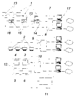
Figure 1 shows an evacuation system having escape identification lights 1,
moni-
toring sensors 2 in the form of fire alarms or the like, and having means for
activat-
ing public address devices 3, elevators 4, doors, gates 5, and communication
de-
vices 6, which are all connected to a central computing system 7. In the
exemplary
embodiment shown, the central computing system comprises three computers 8,
9, 10 networked with one another via an interface 11, one each for the
activation
CA 02597646 2007-08-13
-6-
of the escape identification lights 1, the monitoring sensors 2, and building
devices
12. The central computing system 7 analyzes data from the monitoring sensors 2
and alternately releases or blocks the escape routes as a function thereof by
tar-
geted activation of building devices 12 and escape identification lights 1.
The escape identification lights 2 comprise a control unit 15, which may be
cou-
pled to a display 13 and is connected via a network 14 to the computing system
7,
which is alternately coupled to one or to at least two displays 13 via
interfaces 16
for activation. Each control unit 15 is connected via the computing system 7
and
the network 14 to at least one control computer 17 for monitoring and program-
ming, a unique network identification being assigned to each control unit 15
and
each display 13. The control computers 17 may be connected to one another via
a
network.
As indicated in Figure 2, the displays 13 and the control unit 15 form a
module re-
movably connected to one another, by which it is alternately possible to
install the
dispiay 13 and control unit 15 jointly or use a central control unit 15 for
multiple
displays 13, without having to accept an increased construction outlay.
The control unit 15 has a processor including interface 18, network interfaces
14
(parallel, serial, ethernet, or the like), a ciock 19, at least one memory 20,
as well
as a power supply unit 21 having an emergency running device in the form of a
battery 22. A camera 23, acoustic input and output devices 24, and possibly
addi-
tional lights 25 are also connected via suitable interfaces 26 and/or
amplifiers 27 to
the network interface 14. The possibility thus exists of relaying image
material from
the escape routes to an operator and/or illuminating the escape route or
relaying
information to fleeing individuals and/or accepting information from them.
Improved alarm execution and targeted escape route guiding during evacuation
as
well as direct communication with individuals in affected building areas are
possi-
CA 02597646 2007-08-13
-7-
ble with the present invention. By monitoring via video and/or acoustic
monitoring,
superfluous evacuations may be avoided as much as possible. Fundamentally, of
course, the possibility exists of combining the dynamic escape route guiding
ac-
cording to the present invention with conventional emergency lighting, in
particular
for areas in which only one escape direction is possible.
In case of alarm, the monitoring sensors 2 (fire, gas, smoke alarms or the
like)
communicate the alarm, while specifying their network identification, to the
central
computing system 7, which, on the basis of the alarm data, such as type and
loca-
tion, blocks or releases escape routes in a targeted way by activating
building de-
vices 12 and rescue identifications 1, to guide individuals away from the
danger
point. The data connection between escape identification lights 1 and
computing
system 7 may differ depending on the specification. It is particularly
advantageous
to keep secure escape routes free in a targeted way for the most rapid
possible
access of rescue personnel. Depending on the activation, the escape
identification
lights release a pathway, block it, and/or point individuals in one or another
direc-
tion.