Note: Descriptions are shown in the official language in which they were submitted.
CA 02598007 2007-08-17
Doc No: 18-256 CA Patent
Printed Article with Special Effect Coating
Cross-Reference to Related Applications
[1] The present invention claims priority from U.S. Provisional Patent
Application No.
60/823,774 filed August 29, 2006, which is incorporated herein by reference.
Field of the Invention
[2] This invention relates generally to the provision of an optical device and
method of
manufacture, wherein a light transmissive substrate is printed with lines in
the form of an image
or indicia using an ink and wherein the inked substrate is subsequently coated
with a special
effect coating allowing the special effect coating to be seen between the
printed lines.
Background of the Invention
[3] The use of security devices such as substrates coated with secure coatings
for adhering to
and for protecting banknotes, credit cards and other valuable documents is
well known. Some of
these security devices provide the advantage of being decorative as well. By
way of example,
however not limited thereto, a security thread is a strip of material placed
on the surface of a
banknote document or sheet such as banknote; alternatively a security thread
may be
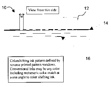
serpentined or woven into the banknote paper (a window type effect) to confer
additional
security (authenticity) to the bank note. Typical dimensions of a hot stamp
thread are a width of
1-5 mm, a thickness of 3-4 µm; windowed polyester terephthalate (PET) based
threads have
a thickness of about 0.5 mil or 12.5 microns. By way of example, one of the
earliest forms of
security threads consisted of reflective foil transferred by hot stamping to
the surface the
banknote (GB 2119312 A). This reflective foil prevented reproduction of
counterfeit banknotes
by printing processes such as from printing presses, PC printers and copiers.
Holograms (EP-A-
0624688), holographic features along with thermo chromic features (GB
2347646), opaque
coatings having characters and patterns readable by transmitted light in
combination with
luminescent substances (U.S. Pat. No. 6,474,695), repeating patterns of
magnetic/magnetic
indicia or metal dots (W02103624), laser etching fine lines and text with a
laser (German
"Auslegeschrift" no. 22 05 428) and (W002101147), printing micro-characters on
a metalized
transparent plastic with clear acid resistant inks followed by acid etching of
the unprinted areas
1
CA 02598007 2007-08-17
Doc No: 18-256 CA Patent
to produce shiny micro-characters on a transparent base (U.S. Pat. No.
4,652,015), bonded
nucleic acid molecules so that complementary nucleic acid molecules can bind
to the molecules
already attached to the document (DE 10122836), and optically variable
security elements using
liquid crystal material (EP0435029) have all been used to make security
threads. However, these
aforementioned optical device either take too much time to make and or have
other associated
problems; for example, it is found that laser etching takes too long to be
cost effective, etching
by use of chemicals requires multiple steps and is not considered to be
environmentally-
friendly; holograms can be readily copied, and in many instances the features
of these security
devices are not readily seen by eye by the average person and machines are
required to read
them.
[4] A method to pattern a single layer of metal or carbon in a vacuum chamber
was advanced
in U.S. Pat. No. 4,022,928 by Piwcyzk. Piwcyzk used various methods to apply a
perfluoropolyether known as FOMBLIN TM. or Krytox TM to a substrate requiring
a pattern
for a vacuum deposited layer. The perfluoropolyether inhibited the deposition
of the depositing
material to a web or plastic substrate. Application of this fluid was by spray
or vacuum
evaporation in combination with a selected removal process as with a laser or
an electron beam.
A printing method was also described for applying the perfluoropolyether.
Printing techniques
including relief printing such as letterpress or flexography, planographic
printing such as offset
lithography, and gravure, and screen-printing such as silkscreen process
printing were disclosed.
[5] Subsequently, Ronchi in U.S. Pat. No. 4,749,591 incorporated herein by
reference, and in
PCT application WO 8700208(A1)) advanced this printing process by applying the
inhibiting
oil, FOMBLIN, to a vacuum roll coater where patterning thin films on plastic
substrates was
desired.
[6] A major impediment to providing several thin film layers, was residual oil
remaining on
the images and on non-patterned areas of the web. This residual oil was
detrimental to further
thin film coating since left over oil would cause "ghosting"; a process
whereby the inhibiting oil
2
CA 02598007 2007-08-17
Doc No: 18-256 CA Patent
is transferred to the back side of plastic film when roll coating, which in
turn causes inhibiting
oil to be transferred further down the web on the front side. Left over
inhibiting oil also causes
adhesion failures to subsequent thin film layers.
[7] In an effort to overcome impediments related to using inhibiting oil in
providing a
windowed image other techniques have been considered which use optically
variable coatings.
181 Optically variable inks or coatings are composed of optically variable
pigments,
suspended in an ink, paint, or coating vehicle which is typically a polymer
resin and may also
contain other pigments, dyes, and additives. Optically variable pigments, such
as the vacuum
deposited optical multilayer pigments SecureShiftTM, ChromaflairTM and OVPTM
pigments from
JDSU Corporation, mica based pearlescent pigments such as those available from
Englehard,
Merck and others, and liquid crystal pigments are dependent for their effects
on the layered
structure and orientation of plate-like particles. For this reason, rather
large platelets, typically
ranging in size from a few micrometers to about 100 micrometers are preferred.
If the particles
become too small they fail to orient properly, and the brightness, purity, and
degree of color or
brightness change effects are reduced. The average size of such particles is
typically larger than
about 5 microns.
[91 The platelet form of optically variable pigments results in difficulty in
the production of
fine features in printing processes. The optically variable particles
themselves have dimensions
much larger than those of conventional ink pigments which on average are
smaller than 5
microns, and this leads to difficulty in dispersing the platelets and printing
using conventional
printing techniques. The printing of fine features requires that the pigment
particles be
significantly smaller than the feature size to be printed, so that the feature
will appear to be
continuous. This requirement is familiar from observation of displays composed
of discrete
elements, for example television and computer display screens, where picture
features which
approach the size of the display elements (pixels) become blurred and
indistinct. There is a
further problem with printing inks which have platelets larger than the
desired feature size. Such
3
CA 02598007 2007-08-17
Doc No: 18-256 CA Patent
platelets "bridge" across any closely spaced print regions of the printing
plate, thus merging the
regions in the printed article. Thus, even if the color shift areas are large
compared to the
platelet sizes, there can be no thin line boundaries between the color shift
area and other printed
features due to this bridging effect by the pigment particles.
[101 One way in which these difficulties might be overcome, is to overprint
fine contrasting
and masking features on top of the optically variable ink features with a
conventional fine
particle ink. However, in practice it is not possible to get high print
quality with this method,
because the optically variable ink layer is thick, particularly in the case of
magnetically oriented
optically variable ink such as JDSU "PhantomTM" ink, or mica-based pigmented
inks, and the
ink surface itself additionally may be quite rough due to the relatively large
platelets embedded
in the optically variable print region. Thus it is very difficult to overprint
an optically variable
ink pattern with a fine line closely controlled edge pattern. Close control of
the placement,
impression force, and consistency of ink application in a fine line pattern is
not possible when
printing on a non-planar surface.
[11] The difficulties inherent in producing high resolution features using
optically variable
inks and coatings are overcome by the method of the present invention, in
which the high
resolution features are defined by printing with conventional inks, which
comprise very fine or
nanoparticulate pigments capable of printing high resolution features. The
features are printed
reversed on the substrate, leaving openings through which the optically
variable component or
layer may be viewed. Thus, it is only necessary for the optically variable
layer to be printed
behind the entire area which has openings for its viewing in the opaque print
layer. In use, the
article is viewed from the unprinted substrate side in the case of a
transparent substrate, either
as a label or printed article or as a hot stamp transfer to a receiving
support article.
[12] The optically variable component may be applied over the openings in the
high resolution
printed area either as an ink or coating, as optically variable pigment in an
adhesive layer, or as
a direct vacuum coated layer. Since the high resolution printed layer acts as
a viewing mask
4
CA 02598007 2007-08-17
Doc No: 18-256 CA Patent
when viewed from the substrate side, the optically variable component may be
applied
uniformly over the entire article, thus obviating the need for high resolution
or fine features in
the optically variable layer. Optionally, to conserve what may be costly
optically variable ink or
pigment, the optically variable component may be applied only to completely
cover and overlap
the open areas of the opaque ink mask.
[13] Further, the application of the optically variable ink behind a
conventional ink mask
renders possible the production of individual items with unique content such
as serial numbers,
bar codes, images, and the like formed of optically variable effects by using
for example inkjet,
thermal transfer, or electrostatic printing methods to define the ink mask.
Direct variable
printing, especially at high resolution, is not practical with optically
variable inks, due to their
large particle size.
[14] This invention provides security a decorative and/or security device
which obviates the
requirement of applying inhibiting oil and provides a simple means by which
windows can be
formed on a plastic substrate. In particular, a new optically variable
security device having a
high pattern resolution was made that contained readable text or graphic
images where covert
features could also be incorporated.
[15) It is an object of this invention, to provide a security device having
optically variable
features such as an optically variable pattern that can be seen against a
background that is
distinguishable from the pattern, or from which the pattern stands out.
1161 It is an object of this invention to provide a reverse printed image
having gaps defined
within the image defining windows, printed directly upon a light transmissive
substrate, wherein
gaps within the reverse printed image are coated thereover with a special
effect coating of
flakes, wherein the flakes can be seen through the substrate and wherein one
of the reverse
printed image and the flakes provide a background color for the other.
5
CA 02598007 2007-08-17
Doc No: 18-256 CA Patent
1171 Special effect flakes include but are not limited to: color shifting
flakes, color switching
flakes, diffractive flakes; reflective flakes, covert flakes carrying covert
information;
purposefully shaped flakes, for example uniformly shaped flakes; magnetic
flakes; magnetically
alignable flakes, flakes containing fluorescent light emitting and/or
wavelength conversion
phosphors which respond to illumination at a first wavelength and emit energy
at another
wavelength, and / or combinations thereof. Special effect coatings are
coatings comprised of a
carrier having special effect flakes therein wherein the carrier in
combination with the flakes
may provide a special effect.
Summary of the Invention
[18] In accordance with the invention, a security device is provided
comprising: a light
transmissive substrate supporting on a first side thereof, a plurality of
printed regions, wherein
spaces between some adjacent regions have a width Wl that is less than or
equal to P1, and a
special effect coating supported by the substrate and covering at least some
of the spaces
between the adjacent regions, wherein the special effect coating has an
average particle size of
greater or equal to 5 microns.
[19] In accordance with the invention, there is further provided, an article
incorporating a
color shifting pattern or design comprising a light transmissive substrate, a
high resolution
pattern printed on one side of said substrate in which unprinted transparent
areas are provided,
and a color shifting ink, coating, or film applied over said high resolution
ink pattern so as to be
visible through openings absent of ink in the ink pattern from the unprinted
side of the
transparent substrate.
[20] In accordance with the invention a method of forming a security device
having a first side
and a second side is provided comprising the steps of
[21] providing a light transmissive substrate;
[22] printing an image having regions of ink separated by spaces that are not
printed upon the
light transmissive substrate; and,
6
CA 02598007 2007-08-17
Doc No: 18-256 CA Patent
[23] coating regions of the substrate with a special effect coating such that
at least some of the
non printed spaces are covered, wherein patterned inked regions are visible
and the special
effect coating is visible simultaneously, when viewing one side of the device.
1241 In accordance with another aspect of the invention there is provided a
security device
comprising:
1251 a light transmissive substrate;
[26] a reverse inked image printed thereon, having printed regions adjacent to
one another
having un-inked spaced regions therebetween, wherein the width of the spaces
between some
regions is less than WI; and,
[27] a coating of special effect flakes covering at least some of the spaces
having a width of
less than W 1, wherein the largest particle size of the special effect flakes
is greater than W 1.
Brief Description of the Drawings
[28] Fig. 1 is a cross sectional side view of a reverse printed image printed
upon a light
transmissive substrate, wherein the image is flood coated thereover with a
color shifting
pigment ink or adhesive.
[29] Fig. 2 is a plan view of an image having fine lines printed on one side
of a substrate and
having a flood coat of special effect flakes thereover.
Detailed Description
[30] The term security device referred to hereafter is meant to include any
form of identifier
that can be used to authenticate the device; and although the device described
hereafter can be
used as a decorative label or cover it inherently provides a measure of
security for
authentication.
[311 Referring now to Fig. I a security device 10 is shown having a light
transmissive
substrate 12 that is transparent allowing an image placed on one side to be
seen from the other
side of the substrate. The substrate is shown as having two planar surfaces,
however the upper
surface may optionally have a microstructure not shown in the figure, such as
a grating defined
therein, spaced portions of the upper surface thereby providing diffractive
effects in desired
regions. In the manufacture of the device 10, a pattern 14 is reverse printed
upon the lower
7
CA 02598007 2007-08-17
Doc No: 18-256 CA Patent
surface of the transparent substrate 12 using conventional ink. The reverse
printed image is
printed so that the text or image appears readable when viewing it through the
substrate. It is
preferable that a particle size within the conventional ink be as small as
possible so that
adjacent printed regions can be separated by very thin, clear, unprinted
regions without
scalloped edges.
[32] After the inked pattern 14 is applied to the substrate and the ink has
dried, a portion or all
of the inked image including gaps between inked regions is flood coated with
color shifting ink
or paint 16 having color shifting flakes 18 within a carrier. Alternatively, a
color shifting
adhesive having flakes therein may be used, for example a hot-stamp adhesive
having color
shifting flakes therein. Although color shifting flakes are coated over the
dried non-color
shifting inked pattern 14 as shown, color shifting flakes or any other special
effect flakes can be
used. Combinations of different special effect flakes may also be used. For
example color
switching flakes such as highly reflective aluminum flakes in a tinted
carrier, or diffractive
flakes, or covert symboled flakes or combinations thereof can be used to coat
over the fine lined
conventional inked pattern. The particular advantage in providing a
transparent substrate printed
with "conventional small platelet" printing ink coated thereover with special
effect flaked ink is
that a very crisp image having what appears to be very fine lines of special
effect ink or paint is
seen when looking through the substrate. Such visually apparent fine lines of
special effect
flaked pigment seen through a fine lined mask could not otherwise be provided
by printing the
visible pattern with the special effect ink, as the flakes would be too large
to allow fine line
spaces therebetween. Stated differently, if one reverses the process and first
prints the fine line
pattern with conventional special effect color shifting flakes ranging in size
from 5 to 100
microns, and subsequently coats the printed image with conventional printing
ink, the image
would not appear as crisp to the viewer and scalloped edges would be much more
evident in the
image. In the embodiment shown, it is important that the smaller particle size
ink be used upon
the substrate subsequently coated with large size pigment flakes. There is
only one instance
where the order of coating is of little or no consequence. That is in an
embodiment where the
fine lined coating is printed on a first viewing side of the substrate and
wherein the flood coated
special effect ink or paint is coated on a second opposite side of the light
transmissive
substrate. However, this embodiment is less preferable than applying the
special effect ink
8
CA 02598007 2007-08-17
Doc No: 18-256 CA Patent
directly upon the conventionally reverse inked printed image. Depending on the
thickness of
the substrate there may be a visible parallax between the coating layers. If
spot printing of color
shift in areas of windows is used, printing on the two sides of the substrate
would have to be in
registration which is an additional requirement. Furthermore, in this less
preferred embodiment
preventing abrasion or weathering of the front surface ink which is not
protected by the
transparent substrate might require a protective coating or lamination which
adds cost and
process complexity. In this embodiment both sides of the substrate must be
suitable for
receiving ink, which might compromise other properties such as abrasion
resistance which is
desirable on the outward facing surface. In general, printing on both sides of
the substrate is a
more complex process.
133] Referring once again to Fig. 1, in an alternative embodiment, the color
shifting ink or
paint 16 can be selected such that it shifts from a first predetermined color
to a second
predetermined color, wherein one of the first and second colors matches the
color of the inked
pattern 14. Thus, by tilting the image, the color shifting ink 16 is either
distinguishable from the
inked pattern 14, or closely matches the pattern 14. It should be understood
that in this
embodiment, when the printed coated image is viewed through the substrate, it
appears as if the
inked region and color shifting inked regions are side-by-side, although the
color shifting
coating is coated over the entire conventionally inked printed region and
covers spaced
therebetween.
1341 In the embodiment shown in Fig. 2 a more complex image is shown, having a
design of
very even spaced fine printed lines 24 printed with conventional ink upon a
substrate 22. A
flood coat of highly reflective flakes 26 is printed over the lines 24
covering both the lines and
fine spaces therebetween. By appropriately choosing the line width and width
of spaces
therebetween, a grating is formed having visible diffractive properties.
[35] In another embodiment of the invention fine printed lines are provided on
both sides of
the substrate, either aligned or offset with each other. If the lines and
spaces on both sides of the
substrate are of a similar spacing and dimensions and suitably arranged
compared to the
thickness of a transparent substrate, a variety of variable image effects can
be produced
9
CA 02598007 2007-08-17
Doc No: 18-256 CA Patent
including something of a color-shifting and shape shifting moire interference
pattern due to the
interaction of the two fine patterns as the substrate is tilted. Achieving
such a moire pattern or
structure could not be done with coarse or fuzzy printed patterns alone, and
also relies on the
transparency of the substrate. In accordance with this invention the lines on
the front (observer)
side of the substrate must be printed with conventional ink with windows or
alternatively a
demetallized Al or other colored thin film layer(s). The opposite side would
have a coating as
described heretofore, wherein "apparently" fine lines of special effect ink
are provided through
a mask of convetionally printed ink having fine line gaps between regions.
(36] A discussion of moire patterns is found at
http://en.wikipedia.org/wiki/Moir%C3%A9-pattern. The structure shown would
require printing
on both sides of the substrate so that the parallax gives the moire a
"motion". The effect can be
illustrated by overlaying two layers of window screen and moving them linearly
and rotating /
tilting them.
(37] To produce moire effects, the lines need not be straight, in fact the
configuration of the
lines and their interaction is a design parameter. In this case, moire is a
desired effect unlike in
most printing where it is an undesirable artifact.
1381 The device of Fig. 1 may be hot stamped to an article, for example to an
identity card,
currency a poker chip creating a decorative label that offers a high degree of
security and which
can be authenticated. Hot stamping is a coating system that is transferred
from a support to the
finished article, in which case the "transparent substrate" to which the
printing is applied is the
stamping release/coating layers carried on a support foil.
1391 Although in preferred embodiments of this invention shown heretofore,
reverse printing
was utilized, in an alternative less preferred embodiment of the invention as
mentioned above,
the inked pattern can be printed on top of the substrate on the viewing side
and the flaked
coating of special effect flakes can be printed on the opposite non-viewing
side of the device.
An advantage of the preferred embodiment wherein the special effect coating is
printed over the
conventional reverse printed ink on the same side of the substrate is that no
protective lacquer
CA 02598007 2007-08-17
Doc No: 18-256 CA Patent
coating is required. In further embodiment the substrate may be printed over
on the face side to
incorporate security features such as tamper-evidence.
Further advantages of the Invention
[401 Additional advantages of applying the optically variable component behind
a high
resolution reverse printed ink layer which defines the optical variable
viewing area are:
[41] An optically variable ink tends to lie flat against the viewing aperture
as it settles after
application, thus giving more vivid and specular optical reflection.
1421 If using a magnetically aligned optical effect ink, it may be applied
thickly to permit out-
of-plane orientation of the platelets, otherwise not consistent with fine
features and sharp edges.
[43] The overlying substrate (or hot stamp protective layer) provides inherent
protection
against the abrasion, chemical attack, or removal of the optically variable
component - a further
protection against alteration.
1441 By virtue of the ability to sharply define small optically variable areas
and patterns,
smaller patches, labels, planchettes, and patterned threads may be made, for
example for
embedding in currency or value document paper.
[451 Any appropriate printing method may be used to print the first-applied
conventional ink
print areas.
[461 In addition to the use of reverse printing with optically variable inks,
as discussed above,
reverse printing may also be used to define viewing areas through which a
directly deposited
(for example by vacuum or solvent coating means) optically variable multilayer
coating may
seen. It is impractical and costly to directly pattern such coatings by
lithographic means,
especially as they are composed of multiple layers of different metals and
dielectric materials,
which often must each be etched by different processes.
1471 Further, as well as acting as an opaque mask to define visible area of
optically variable
coating or ink, the reverse printed ink may also printed in various colors,
including colors which
contrast or match with the optically variable coating(s) visible through the
apertures in the ink
layer, thus forming a unified design or image or information bearing pattern
of which the
11
CA 02598007 2007-08-17
Doc No: 18-256 CA Patent
optically variable layer is one component. In particular, a hidden image or
text composed of
optically variable elements may be incorporated into a printed image by using
small image
elements (pixels) of optically variable coating or ink which are visible
through windows in the
conventionally printed image as described above.
[48] In addition, the color of the optically variable pigment, and its optical
shift, may be
modified by the addition of further components to the ink, including dyes,
conventional
pigments, ultraviolet or infrared active phosphors, including infrared excited
visible emitting
and ultraviolet excited visible emitting materials, for example, while
retaining the effect of
optical variation and the advantages of the reverse printing method described
above for the
production of fine features.
Exemplary Embodiment:
1491 Black and white images containing a pattern of fine lines similar to
those often used in
security printing applications were chosen to demonstrate the invention. To
produce the ink
mask, the image was printed on overhead transparency film using a laser
printer at an
approximate resolution of 600 dots per inch. The results are images on
transparent film
comprised of a black field (laser printer deposited black toner ink) with the
fine lines comprising
transparent areas in the image. A sample of these images is shown in Fig. 4 as
printed on white
paper for better viewing. The white regions in Fig. 4 are unprinted and are
transparent when
printed on a light tranmissive substrate in accordance with this invention. In
an embodiment not
shown, the substrate can be tinted to provide color to the coating of flakes.
[501 To produce a color shifting image the non-viewing image bearing side of
the substrate
was covered with a layer of optically variable pigment in binder, by silk-
screening a thin layer
of 20% concentration of pigment in ink binder over the entire image area. When
viewed from
the non-inked side of the transparent substrate, a fine line color shifting
pattern on a black laser
printed background is obtained.
12
CA 02598007 2007-08-17
Doc No: 18-256 CA Patent
[51] This exemplary embodiment demonstrates the basic principle of reverse
printing to
produce fine line images which cannot be directly printed, the use of digital
imaging processes
in conjunction with color shifting inks and coatings to produce images, and
the use of variable
image reverse image printed masks to produce individually coded color shifting
features. Inkjet
and thermal transfer printing may be incorporated into a printing line to
produce the ink masks.
[52] It is easily seen that by incorporating colored inks into the image in
whole or in part to
replace the black toner mask, that metameric and hidden color shifting
information may be
produced at high resolution by this process. Further, by incorporating
continuous line printing
techniques such as flexography and lithographic printing, fine and continuous
features may be
produced.
13