Note: Descriptions are shown in the official language in which they were submitted.
CA 02598229 2007-08-16
SUpm 050262W0
21 February 2006
Means and device for compensating for a local deformation of the cornea of an
eye
The present invention relates to a means and a device for compensating for a
local
deformation of the cornea of an eye.
A means of this type and a device of this type are used for compensating for a
local
deformation of the cornea of the eye, especially of the human eye. However,
they can also be
used for treating the eye of a different creature.
Owing to diseases and/or injuries, the cornea of a human eye can experience
reductions in
thickness causing, under the influence of the aqueous humour pressure, the
cornea contour,
which is spherically shaped in the healthy state, to have local outwardly or
inwardly shaped
archings. This leads to a change in refraction with in some cases substantial
distortions of the
cornea (astigmatisms) for which neither glasses nor contact lenses are able to
compensate
satisfactorily. Severely restricted sight is the result. Such deformation of
the cornea is known
as keratoconus or keratectasia.
In the past, arching or bulging of the cornea has been eliminated using feed
tools which are
introduced from the outside and with which an approximately annular channel or
tunnel is
positioned purely mechanically and manually in the healthy region of the
cornea. The channel
or tunnel acts as a receptacle for the insertion of implants which are
generally made of a
transparent plastics material such as polymethyl methacrylate (PMMA). Implants
of this type
are known in practice as "INTACS".
In the known method, two implants, which are arcuate in their longitudinal
extension, are
inserted, for example, into two corresponding receptacles, located in a common
plane, in the
healthy region of the cornea. The implants may in this case encompass, for
example, an
angular range of less than 180 and are conventionally inserted into the
cornea facing one
another so as at least partially to encompass the abnormally arched region of
the cornea.
When inserted into the cornea, the implants exert a tensile force onto the
arched region of the
CA 02598229 2007-08-16
2
cornea as a result of the fact that they rest against a wall of the respective
receptacle. This
reshapes the arching.
The known method originates from the treatment of myopia (short-sightedness)
and was
approved in 2004 by the US Food and Drug Administration (FDA) as a method for
the
treatment of keratoconus and keratectasia patients.
Operating methods of this type have the drawback, in particular, of requiring
patient
convalescence and aftercare lasting several months. Further drawbacks include
the scarring
effects resulting from lacerations and the resultant astigmatism.
There are also often introduced into the respective receptacle, during
preparation, epithelial
cells which can produce undesirable deposits on the INTACS. The endothelial
cells extending
on the inside of the cornea are also inevitably damaged during carrying-out of
the known
operating method owing to the tensile and compressive loads.
In the case of advanced findings, complex deimplantation/reimplantation of the
cornea
(perforating keratoplasty) has to be carried out.
A further drawback of this operating method is that, owing to the fixed
incision width, there is
no variability on introduction of the channels for the implants, and this can
cause more or less
pronounced stress in the treated cornea. The known method therefore often does
not provide
sufficiently precise compensation for the local deformation of the cornea and,
in particular,
the complex stress conditions occurring in the region of the deformation, so
the deformation
also cannot be optimally eliminated.
The object of the present invention was therefore to specify a means of the
type mentioned at
the outset allowing improved compensation, compared to the prior art, for
local deformation
of the cornea of an eye. Also to be specified is a device of the type
mentioned at the outset
which minimises, with improved compensation for a local deformation of the
cornea,
undesirable side effects and/or repercussions for the patient.
With regard to the means, this object is achieved by a means for compensating
for a local
deformation of the cornea of an eye, having a set comprising at least two
implant members for
CA 02598229 2007-08-16
3
insertion into at least one receptacle inserted into the cornea, wherein at
least two implant
members are arranged in differing planes located one above the other.
The means according to the invention has a set for insertion into a receptacle
inserted into the
cornea. The set comprises in this case at least two implant members arranged
in differing
planes located adjacently to one another and one above the other. The set may
both be of one-
piece configuration and comprise two implant members which are not directly
joined
together. The arrangement of the implant members in two planes is maintained
in this case,
especially after insertion into the cornea. The implant members are provided,
in particular, for
insertion into the region of the cornea that is not affected by the
deformation. The receptacle
into which the implant members are respectively inserted may in this case, in
particular, be in
the form of a channel.
The fact that, in accordance with the invention, at least two implant members
are arranged in
differing planes allows for the complex stress conditions in a deformed
cornea. Such
arrangement of the implant members allows differing forces to be exerted by
the implant
members in differing planes of the cornea. In this way, it is possible to
compensate in a more
precise manner than in the prior art for the stress conditions prevailing in a
deformed cornea,
and thus for the deformation of the cornea. In particular, differing stress
conditions prevailing
in various planes of the deformation of the cornea may in this way be
compensated for more
effectively.
Mechanical damage to the arched and thickness-reduced region of the cornea may
in this case
be avoided and local arching in the cornea compensated for by implant members
inserted into
the cornea, especially in the environment of the arching and therefore the
healthy region.
Suitable matching of the formation of the receptacle in the cornea and the
formation of the
implant members to be inserted into the receptacle allows adjustment of the
force exerted by
each implant member onto the cornea and thus, in particular, onto the deformed
region.
The tension properties of the implant members may be brought about during the
manufacturing process by changes or deviations in the material condition,
shape and volume
in the extension of the element. The forces to be exerted onto the receptacle
formed in the
cornea may, for example, be introduced over the entire longitudinal extension
of the implant
members or merely in certain portions.
CA 02598229 2007-08-16
4
The tension forces exerted by the implant members may, for example, be
produced from
already integrated stresses or from stresses built up as a result of the
insertion into the cornea.
In particular, the tension forces may originate from the geometrical
configuration of the
implant member and the associated receptacle.
The implant members may in this case be mounted concentrically or
eccentrically in the
receptacles provided for them. If the implant members abut the internal or
external
circumference of the receptacle, the tension forces may, for example, act on a
perpendicular
wall of the cornea receptacle.
According to a preferred embodiment, provision is made for the implant members
to be
configured in such a way that, when inserted into the cornea, at least one
implant member
exerts a compressive force and at least one implant member exerts a tensile
force onto the
region of the local deformation. According to this embodiment, the implant
members
arranged in differing planes are able to exert onto the deformation of the
cornea forces acting
in differing, especially opposed, directions, i.e. tensile and compressive
forces. This
embodiment allows even more precise compensation for the tension conditions
prevailing in
the deformation.
According to a particularly preferred embodiment, the implant member exerting
the
compressive force may be provided for insertion into a distal plane of the
cornea and the
implant member exerting the tensile force may be provided for insertion into a
proximal plane
of the cornea. The distal plane is in this case further removed than the
proximal plane from
the centre of the eye. It has been found that an increased tensile stress is
provided in the distal
region of the deformed cornea, whereas a lower tensile stress is produced in
the proximal
region of the deformed cornea. This embodiment therefore provides optimum
compensation
for these stress conditions and thus for the deformation of the cornea.
In extreme cases, there may even be compressive stress in the proximal region
of the cornea.
In this case, the cornea may have in the deformed region what is known as a
"neutral strand"
above which there is a tensile stress and below which there is a compressive
stress. In this
case, it is advantageous if the implant member exerting the compressive force
is provided for
CA 02598229 2007-08-16
insertion into the cornea above the neutral strand and the implant member
exerting the tensile
force is provided for insertion into the cornea below the neutral strand.
In practice, it has been found to be especially suitable if at least one of
the implant members is
configured so as to be arcuate in the direction of its longitudinal extension.
Implant members
which are arcuate, especially circle-arcuate, in their longitudinal extension
can be adapted
particularly effectively to the geometry of the deformation of the cornea,
especially to its
frequently circular limitation, and apply the forces respectively associated
therewith. In
addition, the arcuate formation allows the implant member to be arranged so as
at least
partially to encompass the deformation of the cornea. A force exerted by the
respective
implant member onto the deformed region thus acts in a highly uniform manner
on the
deformed cornea region. Similarly, all of the implant members may, in
particular, be of
arcuate configuration.
According to a preferred teaching, the arcuate implant member may encompass an
angular
range of less than 360 . An implant member of this type may be introduced in a
simplified
manner, starting with one of its ends, into the receptacle provided in the
cornea of the eye.
More preferably, the arcuate implant member may encompass an angular range of
less than
180 . In this way, it is possible to provide respective implant members on
opposing sides of
the arching of the cornea. Firstly, implant members provided on one side of
the deformation
may in this case be arranged in differing planes. Additionally or
alternatively, however,
implant members arranged on opposing sides of the deformation may each be
arranged in
differing planes. This large number of variations ensures that precise
compensation may be
provided for any type of deformation of the cornea, for example even an
asymmetrical
deformation.
Provision may be made for the arcuate implant member to have a second
curvature, the
curvature vector of which is located substantially perpendicularly to the
curvature vector of
the arched curvature. According to this embodiment, the implant member has not
only an
arcuate curvature in the longitudinal direction but also a second curvature in
a direction
perpendicular to the arched curvature. In this way, the implant members can be
optimally
adapted to the spherical contour of the cornea. The second curvature may in
this case also be
arcuate. In particular, the base area of the implant members may extend
parallel to the surface
of the cornea (both internally and externally), so deformation of the cornea
is prevented
CA 02598229 2007-08-16
6
transversely to the curvature of the cornea by pressing the implant members
through.
Obviously, the receptacle provided for each implant member may also have a
corresponding
second curvature. Of course, the implant member or the associated receptacle
may also have
further curvatures in further directions.
Since the aim is to reshape the affected thin-walled and outwardly shaped
cornea region in
such a way that it is optimally adapted to the remaining spherically curved
surface of the
cornea, use is expediently made of a plurality of control variables, such as
the implant
member and the receptacle, in order thus to be able purposefully to produce
adequate stresses
and deformation paths. In particular, it may in this case be expedient to
carry out, locally and
in a coordinated manner, geometric variations to the implant member and/or
shape of the
receptacle. Alternatively or additionally, all of the possible adaptations of
the geometry of the
implant members may, of course, also be carried out on the shape of the
receptacle in the
cornea.
According to one embodiment, at least one of the implant members may be of
meandering
configuration. As a result of this embodiment, it is possible, depending on
the formation of
the meander, to introduce forces purposefully adapted to the deformation of
the cornea into
the cornea through the implant member. In particular, the regions of the
implant member in
which the meander has turning points lead in this case to an introduction of
increased force
owing to reinforced supporting on the receptacle. A suitable configuration of
the meander and
the associated receptacle therefore allows the introduction of force into the
cornea to be
individually adjusted and even more flexible compensation for the deformation
of the cornea
thus to be achieved. The meander may in this case, in particular, have
differing numbers,
differing distances and/or differing positions of the alternating or turning
points and/or
differences in both the external and the internal radii, especially the radial
differences between
the largest and smallest diameter of the meander (frequency and amplitude).
Increased flexibility on introduction of compensatory forces into the cornea
may also be
achieved in that at least one of the implant members is of polygonal
configuration. An
embodiment of this type also allows the effect of the implant member to be
optimally adapted
to the configuration of each deformation of the cornea. A hexagon is cited
merely as an
example of a suitable polygonal shape.
CA 02598229 2007-08-16
7
The effect of the means may also be individually adapted in that at least one
of the implant
members has differing strength and/or elasticity values along its longitudinal
extension. As a
result of the differing strength and/or elasticity values, the tension forces
exerted by the
implant member onto the cornea vary as a function of the strength and
elasticity of each
member portion. The implant member may therefore also in this way be
individually adapted
to the deformation of the cornea for which compensation is to be provided.
A further embodiment provides for at least one of the implant members to have
a wedge-
shaped cross section. A corresponding configuration of the wedge-shaped cross
section allows
forces to be introduced in an especially purposeful manner. The edge of the
wedge should in
this case point in the respective direction in which force is intended to act,
as in this direction
the wedge-shaped implant member exerts a comparatively large force. The
implant member
may thus, for example, have a triangular cross section.
The configuration of the set with two implant members which are not directly
joined together
has the advantage of providing robust elements which may be optimally handled.
A one-piece configuration of the set according to the invention, on the other
hand, has other
advantages. Thus, in the case of a one-piece set, the compensation for the
deformation of the
cornea is achieved by the insertion of merely one component into the cornea.
There is
therefore no need to form two receptacles in the cornea and to position in a
complex manner
two implant members relative to each other in the cornea in order to achieve a
desired
introduction of force into the cornea. An alternative embodiment of the
invention therefore
provides for it to be possible for the set to be of one-piece configuration.
In this case, the
implant members of the sets are therefore integrally connected to one another.
In the case of a one-piece set, the implant members may be oriented
substantially parallel to
one another and be joined together by a connecting web, the connecting web
being connected
at one of its web ends to a leading end, in the direction of the transverse
extension of the
implant members, of the one implant member and at its other web end to a
trailing end, in the
direction of the transverse extension of the implant members, of the other
implant member.
This embodiment therefore allows, for example, a Z-shaped cross section of the
set to be
produced. The Z shape may in this case be provided prior to insertion into the
cornea.
CA 02598229 2007-08-16
8
However, provision may also be made for the Z shape of the set to be produced
merely by
tensioning on insertion into the receptacle provided in the cornea.
In any case, with a set having a Z-shaped cross section, corresponding
tensioning of the set in
the receptacle provided in the cornea allows both a compressive force and a
tensile force to be
exerted onto the deformed region of the cornea using just one component. The
implant
member forming the leg of the Z shape that is pointed away, when inserted,
from the
deformation of the cornea can in this case exert a tensile force, whereas the
implant member
forming the leg of the Z shape that points toward the deformation is able to
exert a
compressive force. In particular, provision may be made in this case for the
implant member
of the set that exerts the compressive force to be provided for insertion into
a distal plane of
the cornea, whereas the implant member exerting the tensile force is provided
for insertion
into a proximal plane.
According to an especially practical embodiment, at least one of the implant
members may
have a region which can be manipulated using magnetic forces. The implant
member has in
this case a region via which the implant member can be moved using magnetic
forces. It is in
this way possible, in an especially simple manner, to introduce the implant
member into the
receptacle in the cornea in that the implant member is guided using a suitable
magnetic tool.
The loads on the eye that are associated with the intervention are in this
embodiment
minimised, as insertion of the implant member into the cornea does not require
any direct
contact with the implant member.
A transparent material such as PMMA is preferentially used as the material for
the implant
members or the set. This material has proven suitable in practice. In
particular, it combines
good tension properties with good compatibility with the eye. However, in
addition to
PMMA, the material which is mainly used, use may also be made of other
transparent and
anatomically designed materials such as, for example, those having an
irreversible shape-
changing effect (memory) maintained over the entire period during which the
implant
member is used.
If use is made of transparent materials, for example the aforementioned PMMA,
for the
implant members, those having a modulus of elasticity of approx. 600 MPa and
greater are
CA 02598229 2007-08-16
9
preferred, as significant inherent rigidity is required to prevent the cornea
itself from
reshaping.
Further possible materials include those which, when implanted, have already
integrated
inherent stresses or the capacity to build up inherent stresses through
extraneous action.
The materials used for the implant members according to the invention should
in this case not
change their inherent volume during their service life, i.e. in particular not
swell, in order to
ensure uniform action of the implant members.
Materials of this type allow the respectively required configuration, in
particular geometry, to
be selected in an especially individual manner without the implant members
having to be
manufactured specifically for treatment. However, it is also conceivable for
there to be
provided for the implant members a material having a reversible shape-changing
effect
(memory). In this case, it is possible to adapt the implant member, for
example in the event of
the geometry of the cornea changing a relatively long time after the
treatment, to the geometry
now obtaining and thus to continue using the implant member.
The object according to the invention is also achieved by a device for
compensating for a
local deformation of the cornea of an eye, comprising a means for collecting
property data of
the local deformation, comprising a means for simulating the compensation for
the
deformation of the cornea, provided that at least two implant members are
inserted into at
least one receptacle inserted into the cornea, one implant member, when
inserted into the
cornea, exerting a tensile force and one implant member exerting a compressive
force onto the
region of the local deformation, comprising a means for selecting a suitable
combination of a
receptacle to be inserted into the cornea and a means, configured in
accordance with the
invention, to be inserted into the receptacle, in view of the results of the
simulation, and
comprising a means for inserting the receptacle into the cornea. The
receptacle may in this
case, in particular, be in the form of a channel.
In order to achieve, in addition to the technically possible high measurement
precision in the
production of the cornea receptacle and the localising thereof, optimum
operative results,
provisions, such as for example data collection, simulation and optimisation,
have to be made
prior to operation.
CA 02598229 2007-08-16
For this purpose, the device has a means for collecting property data, the
data provided prior
to compensation for the local deformation being obtained using said means.
This data serves
as the basis for the subsequent procedure. The means for simulating the
compensation for the
deformation is used to calculate the repercussions of the compensation for the
cornea arching
(ideal cornea arching) on the healthy environment of the cornea in order
effectively and
reliably to determine the position of the receptacle for the respective
stabilising implant
members. The simulation is carried out on the condition that at least two
implant members are
inserted into at least one receptacle inserted into the cornea, one implant
member exerting,
when inserted into the cornea, a tensile force and one implant member exerting
a compressive
force onto the region of the local deformation. This condition ensures precise
compensation
for the deformation of the cornea.
There may be provided in this case, in particular, a means which produces an
optimisation or
simulation model for the compensation for the deformation of the cornea. The
region of the
cornea to be used for this purpose is conventionally located on a diameter of
approx. 8 mm
based on the axis of the eye (centre point). Annular or partially annular
channels or tunnels
may in this case be inserted as a receptacle into the cornea and inserted into
these
corresponding implant members. Depending on the findings, the receptacles and
implants
may be mounted concentrically or eccentrically.
This region may also be taken as the starting point for the simulation of the
active diameter. A
quadrant circle is positioned in such a way that the cornea arching is located
in a quadrant.
Based on the receptacle and implant member combinations and variations, radial
force action
lines are defined for tension and/or compression force in each quadrant and
the extent and
effect thereof on the compensation for the arching are established. Equally
crucial for the
simulation and awareness of the above-described variables is that of the paths
for reshaping of
the deformation of the cornea.
The most suitable combination of the channel and implant configuration is
selected and
implemented based on the model of the results of directions of action and
active variables in
force and distance. For this purpose, the means is used for selecting a
suitable combination of
a receptacle to be inserted into the cornea and a means which is configured in
accordance with
the invention and is to be inserted into the receptacle, in view of the
results of the simulation.
CA 02598229 2007-08-16
11
The combination, which is the optimum combination for compensation for each
deformation
of the cornea, of the receptacle and means according to the invention for
compensating for a
local deformation of the cornea is selected based on the results of the
simulation. Finally,
there is provided a means for inserting into the cornea the receptacle which
is suitable for the
respectively selected means. The means is then inserted into this receptacle.
The device according to the invention allows undesirable repercussions and
side effects of the
intervention into the eye to be detected as early as the simulation takes
place and accordingly
suitable receptacles and means to be selected in order to minimise such
repercussions and side
effects. At the same time, optimum compensation for the deformation of the
cornea is
achieved by the means according to the invention for compensating for the
deformation.
The data calculated by the means for collecting the property data may, in
particular, be data
concerning the thickness, elasticity, ductility and/or strength of the cornea
in the deformed
region (endothelial microscopy) and/or data concerning the geometry and/or the
position of
the local deformation, especially in relation to the axis of the eye and/or
the healthy cornea
region. All of this data is relevant to the selection of suitable receptacles
and implant
members. Following the topography and determination of the geometric and
material-specific
data of the cornea, an optimisation or simulation model is then produced for
compensating for
the deformation of the cornea.
The non-deformed region of the cornea may also be examined, firstly to avoid
undesirable
side effects on the healthy region during treatment, but also to calculate the
required forces
which are to be introduced and are tolerable for the cornea. The device may
have for this
purpose a means for collecting the property data of the non-deformed region of
the cornea.
All of the property data collected for the deformed region may in this case
also be collected
for the healthy region of the cornea. The spherical formation of the cornea in
the healthy
region may, for example, also be detected in this case.
The device may also have, prior to the inserting of the receptacle, a means
for marking the
region of the cornea that is provided for inserting of the receptacle. Once a
suitable receptacle
has been selected and positioned in the cornea, this means is therefore used
for marking the
region of the cornea that is to be provided with the receptacle before the
receptacle is inserted.
A marking process of this type is interconnected in the event of non-
negligible deviations in
CA 02598229 2007-08-16
12
the contour of the cornea during docking the means for inserting the
receptacle to the eye to
be operated on. In particular, if the means for inserting the receptacle is
docked to the eye
using an adapter, deviations in the contour of the cornea may result from the
pressure ratios
between the low-pressure to be built up in the adapter and the contact
pressure required for
positioning the adapter onto the eye.
The marking means can, for example, transmit the position and shape data
resulting from the
simulation phase to the normal actual state of the eye in such a way that the
coordinates,
which ideally correspond to the selected implant member, of the receptacle
course are applied
to the cornea, for example, using a template which is preferably made of PMMA
and is
adapted to the cornea once the deformation of the cornea has been compensated
for. A
corresponding solution may be achieved using a biometrically exact detection
system
integrated in the field of excimer lasers.
If the means for inserting the receptacle is then docked to the eye, it may be
checked to what
extent the ideal course of the receptacle has been achieved or the means for
inserting the
receptacle has to be corrected in order to ensure this.
It is important that this condition is adhered to, as failure to do so will
directly impair the
success of the operation as a result of the fact that the selected implant
members cannot
function as intended. Thus, for example, inserting of the receptacle causes,
in the case of an
excessively curved cornea, a desired diameter of a receptacle, for example, to
be too large
and, in the case of a cornea which is pressed too flat, a desired diameter of
a receptacle to be
too small. Imprecise alignment leads not only to functional problems but also
to implant
problems and undesirable consequences thereof.
According to a preferred embodiment, the means for inserting the receptacle
may have an
adapter to be attached to the eye for fixing the eye during the inserting of
the receptacle. For
implanting the set, it may be expedient if an adapter is used to support the
desired shape of the
region of the cornea in which implantation is not carried out. An adapter of
this type may, for
example, be configured in a similar manner to a laser adapter known per se
that is adapted to
the patient interface (PI).
CA 02598229 2007-08-16
13
The adapter may be in the form of a truncated cone-shaped funnel. The adapter
proposed in
this case may be of similar configuration to adapters known per se for these
purposes.
However, it has on its circumference a sufficiently large opening to allow the
implant member
to be inserted into the receptacle without obstruction via the section of the
receptacle when the
adapter is attached. In order to provide the operator with optimum visibility
of the operating
field, a wholly transparent material such as, for example, PMMA is, in
particular, suitable as
the material for this adapter.
The engagement opening in the adapter for inserting the implant member should
in this case,
on the one hand, be sufficiently large to ensure trouble-free implantation. On
the other hand, a
contact surface between the adapter and cornea that is as large as possible is
desirable in order
to be able sufficiently to stabilise the shape of the cornea. In practice, a
suitable compromise
has to be found between these two aims.
The means for inserting the receptacle in the cornea may have a laser,
especially a
femtosecond laser. Owing to their good focusability, lasers allow the
receptacle to be inserted
with particular precision in the cornea. The good focusability also means that
the
repercussions brought about by the coupling of energy into the tissue adjacent
to the focus of
the laser during inserting of the receptacle are minimal. Undesirable
repercussions on the
cornea tissue may thus be substantially avoided. Femtosecond lasers are pulsed
lasers, the
pulse durations of which are in the range of femtoseconds. Owing to the short
pulse duration
of lasers of this type pulsed at such high frequencies, energy from the laser
is coupled merely
very briefly into the processed tissue. There is therefore no substantial
spread of coupled-in
energy into adjacent tissue. Undesirable repercussions, caused by heating, on
the cornea tissue
adjacent to the tissue provided for inserting the receptacle are thus further
minimised.
The invention will be described in greater detail hereinafter with reference
to exemplary
embodiments illustrated in the drawings, in which:
Fig. 1 is a partial cross section of the cornea of a human eye with a means
according to the
invention inserted into the cornea in accordance with a first exemplary
embodiment,
Fig. 2 is a plan view of a detail of an implant member according to the
invention in
accordance with a further exemplary embodiment,
CA 02598229 2007-08-16
14
Fig. 3 is a partial cross section of the cornea of a human eye with a means
according to the
invention inserted into the cornea in accordance with a further exemplary
embodiment,
Fig. 4 is a partial cross section of the cornea of a human eye with a
deformation of the cornea
for which compensation has been provided in accordance with a first exemplary
embodiment,
and
Fig. 5 is a partial cross section of the cornea of a human eye with a
deformation of the cornea
for which compensation has been provided in accordance with a further
exemplary
embodiment.
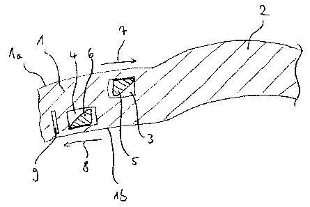
Fig. 1 is a cross section of a detail of the cornea 1 of a human eye. The
cornea has a distal
surface la and a proximal surface lb facing the retina of the eye. In the
cornea 1, a local
deformation 2 is formed in the form of a circularly delimited arching. In the
non-deformed,
healthy region of the cornea 1, two channel-like receptacles 3, 4 have been
formed using a
femtosecond laser.
The receptacles 3, 4 have a rectangular cross section and are of circle-
arcuate shape in their
longitudinal extension. They each encompass an angular range of less than 180
. The centre
of curvature of the receptacles 3, 4 is located in this case approximately on
an axis (not
shown) running through the centre of the deformation 2. The receptacle 3 is
inserted in a
distal plane of the cornea 1 and the receptacle 4 is inserted in a proximal
plane of the cornea
1.
For compensating for the deformation 2 of the cornea 1, implant members 5, 6,
each made of
PMMA, are inserted into the receptacles 3, 4. The implant members 5, 6 form a
set inserted
into the cornea 1, the implant members 5, 6 being arranged in differing planes
defined by the
receptacles 3, 4. The implant members 5, 6, like the receptacles 3, 4, have a
shape which is
arcuate in their longitudinal extension and enclose an angular range of less
than 180 . The
implant members 5, 6 each have a wedge-shaped cross section. The edge of the
wedge of the
implant member 5 inserted into the distal plane of the cornea 1 is in this
case oriented toward
the deformation 2, whereas the edge of the wedge of the implant member 6
inserted into the
proximal plane of the cornea 1 faces away from the deformation 2. The implant
member 5
CA 02598229 2007-08-16
inserted into the distal plane has a smaller curvature than the associated
receptacle 3, whereas
the implant member 6 inserted into the proximal plane has a larger curvature
than the
associated receptacle 4.
On insertion of the implant members 5, 6 into the associated receptacles 3, 4,
the implant
members 5, 6 are accordingly tensioned in the cornea 1. Owing to the
respective ratio of
curvature of the implant member 5, 6 to the receptacle 3, 4, the tensioning
causes the implant
member 5 inserted into the distal plane to exert substantially a compressive
force onto the
region of the local deformation 2 of the cornea 1, whereas the implant member
6 inserted into
the proximal plane produces substantially a tensile force onto the region of
the local
deformation 2 of the cornea 1. The compressive or tensile forces exerted by
the implant
members 5, 6 are indicated in Fig. 1 by arrows 7, 8. On the opposing side (not
shown) of the
deformation 2, two corresponding implant members are inserted into
corresponding
receptacles in the cornea 1.
Owing to the forces introduced by the implant members into the cornea 1 and,
in particular,
into the region of the deformation 2, the local deformation 2 is reshaped in
the desired
manner.
The implant members 5, 6 may have a second curvature, the curvature vector of
which is
located substantially perpendicularly to the curvature vector of the arched
curvature oriented
in the longitudinal direction oriented into the plane of the drawing. In this
way, it is possible
to adapt the implant members 5, 6 to the generally spherical formation of the
cornea 1, thus
avoiding undesirable stresses on insertion of the implant members 5, 6. In
addition, the degree
to which the cornea is reshaped can be enlarged in that, for example, the
implant member 6
for the proximal region has concavely arched roundings (which may not be seen
in the present
case) on the base area and the channel 4 is triangular in cross section. The
roundings may in
this case be distributed uniformly over the length of the implant member 6 or
restricted to
specific portions in order locally to achieve a particular compensatory
effect.
In order to allow the cornea 1 to compensate for any compression caused by the
inserted
implant members 5, 6, a relief chamber 9 is inserted in the cornea 1. The
relief chamber 9
extends on the side of the receptacle 4 that is remote from the deformation 2
substantially
parallel to the receptacle 4.
CA 02598229 2007-08-16
16
Fig. 2 is a plan view of a detail of an implant member 10 according to a
further exemplary
embodiment. The implant member 10 extends in an arcuate manner over an angular
range of
less than 180 and is of ineandering configuration.
At one of its ends, the implant member 10 has a magnet-sensitive region 15
which can be
manipulated using magnetic forces. It is therefore possible to guide the
implant member 10
into a receptacle provided for the implant member 10 using, for example,
magnetic forces
exerted by a permanent magnet onto the region 15 without direct contact with
the implant
member 10 being required for insertion into the receptacle. Impairments of the
eye during
insertion of the implant member 10 are in this way largely avoided.
If the implant member 10 is inserted into an arcuate receptacle which is of
non-meandering
configuration, like the receptacle 11 indicated by broken lines in Fig. 2, the
implant member
introduces into the cornea a differing force, depending on the shape of the
meander. There
is provided in this case a second implant member (not shown in Fig. 2) which
is inserted into
a second receptacle arranged in a plane differing from the plane of the
receptacle 11. The
second implant member and the second receptacle may in this case correspond in
their
configuration substantially to the first implant member 10 and the first
receptacle 11.
However, the implant members and/or the receptacles may also be of differing
configuration.
Obviously, still further implant members may be provided for insertion into
the cornea.
In those regions in which the meandering implant member 10 has a greater
curvature than the
receptacle 11, the implant member 10 exerts, when inserted into the cornea, a
tensile force,
pointed away from the centre of the local deformation (not shown) of the
cornea, onto the
deformed region of the cornea. This is indicated in Fig. 2 by the arrow 12.
Conversely, in
those regions in which the meandering implant member 10 has a smaller or even
opposed
curvature in relation to the receptacle 11, the implant member 10 exerts, when
inserted into
the cornea, a compressive force oriented toward the centre of the local
deformation (not
shown) of the cornea. This is indicated in Fig 2 by the arrows 13, 14. The
second implant
member (not shown in Fig. 2) exerts, when inserted into the cornea,
corresponding forces
onto the cornea. The cooperation of the forces introduced into the cornea in
differing planes
by the implant members provides particularly precise reshaping of the local
deformation of
the cornea. The result of the reshaping may be particularly purposefully
influenced by
CA 02598229 2007-08-16
17
corresponding formation of the meander. This embodiment is an example of a
basically
punctiform or local introduction of forces for both tensile and compressive
forces.
Fig. 3 is a cross section of a detail of the cornea 16 of a human eye. Again,
the cornea 16 has
a distal surface 16a and a proximal surface 16b facing the retina of the eye.
Formed on the cornea 16 is a local deformation 17 in the form of a circularly
delimited
arching. Two receptacles 18, 19 are formed in the healthy region of the cornea
16 on either
side of the deformation 17.
The channel-like receptacles 18, 19 have a rectangular cross section and are
arcuate,
especially circle-arcuate, in their longitudinal extension. They each enclose
an angular range
of less than 180 . The centre of curvature of the receptacles 18, 19 is in
this case located
approximately on an axis (not shown) running through the centre of the
deformation 17.
For compensating for the deformation 17, two sets 20, 21, each of one-piece
configuration,
are inserted into the receptacles 18 and 19. The sets 20, 21 each comprise two
implant
tnembers 22, 23, 24, 25. The implant members of a set 20, 21 are oriented
substantially
parallel to one another and joined together by a respective connecting web 26,
27. The
connecting web 26, 27 is connected at one of its web ends to a leading end, in
the direction of
the transverse extension of the implant members 22, 23, 24, 25, of the one
implant member
22, 24 and at its other web end to a trailing end, in the direction of the
transverse extension of
the implant members 22, 23, 24, 25, of the other implant member 23, 25. When
inserted into
the cornea 16, the sets 20, 21 of this embodiment each have a Z-shaped cross
section.
The leg, formed by the implant member 22, 24 respectively inserted into a
distal plane, of the
Z shape is in this case oriented toward the deformation 17. The leg, formed by
the implant
member 23, 25 respectively inserted into a proximal plane, of the Z shape
points, on the other
hand, away from the deformation 17.
The sets 20, 21 are inserted into the cornea 16 under tension in such a way
that the distal
implant members 22, 24 exert a compressive force onto the deformation 17,
whereas the
proximal implant members 23, 25 exert a tensile force onto the deformation.
This is indicated
in Fig. 3 respectively by the arrows 28, 29, 30, 31. It is thus possible,
using a one-piece set 20,
CA 02598229 2007-08-16
18
21, to exert both a tensile force and a compressive force onto the local
deformation 17 and to
compensate for the deformation especially effectively.
Whereas in Fig. 1 and 3 the local deformation of the cornea is respectively
shown when not
yet compensated for, Fig. 4 and 5 each show a detail of the cross section of
the cornea 32, 33
of a human eye, there being shown in each case the state of the cornea 32, 33
in which
compensation has already been provided for a previously existing deformation
of the cornea.
The cornea 32, 33 has a respective distal surface 32a, 33a and a proximal
surface 32b, 33b
facing the retina of the eye.
Depending on the configuration of the sets for insertion into the cornea 32,
33 and the
receptacles provided for this purpose in the cornea, the deformation may, for
example, be
corrected in such a way that, in the compensated state, the distal surface of
the deformation is
adapted to the distal surface 32a of the healthy cornea 32. This is
illustrated in Fig. 4. The
state is achieved, in particular, if implant members provided in a distal
plane of the cornea 32
exert merely a low compressive force onto the deformation, whereas implant
members
provided in a proximal plane of the cornea 32 exert a dominant tensile force
onto the
deformation. In this case, there may remain in the region of the proximal
surface 32b of the
cornea, even after the compensation, a minor deformation, although this does
not cause any
substantial drawbacks in relation to sight.
Alternatively, it is also possible to adapt the proximal surface of the
deformation to the
proximal surface 33b of the healthy cornea 33. This is the stablest state of
the compensated-
for deformation. This state is shown in Fig. 5. Depending on the intensity of
the deformation,
there may be produced in the region of the previous deformation a slight
arching of the distal
surface 33a of the cornea 33 that can be compensated for using an appropriate
lens. The
compensation illustrated in Fig. 5 is achieved, in particular, in that a
correspondingly
configured implant member exerts a stronger compressive force in a distal
plane of the cornea
33.
CA 02598229 2007-08-16
22
List of reference numerals
1 Cornea
la Distal surface of the cornea
lb Proximal surface of the cornea
2 Local deformation of the cornea
3 Receptacle
4 Receptacle
Implant member
6 Implant member
7 Arrow
8 Arrow
9 Relief chamber
Implant member
11 Receptacle
12 Arrow
13 Arrow
14 Arrow
Region which can be magnetically manipulated
16 Cornea
16a Distal surface of the cornea
16b Proximal surface of the cornea
17 Local deformation of the cornea
18 Receptacle
19 Receptacle
Set
21 Set
22 Implant member
23 Implant member
24 Implant member
Implant member
26 Connecting web
27 Connecting web
28 Arrow
CA 02598229 2007-08-16
23
29 Arrow
30 Arrow
31 Arrow
32 Cornea
32a Distal surface of the cornea
32b Proximal surface of the cornea
33 Cornea
33a Distal surface of the cornea
33b Proximal surface of the cornea