Language selection

Search

Patent 2599042 Summary

Third-party information liability

Some of the information on this Web page has been provided by external sources. The Government of Canada is not responsible for the accuracy, reliability or currency of the information supplied by external sources. Users wishing to rely upon this information should consult directly with the source of the information. Content provided by external sources is not subject to official languages, privacy and accessibility requirements.

Claims and Abstract availability

Any discrepancies in the text and image of the Claims and Abstract are due to differing posting times. Text of the Claims and Abstract are posted:

  • At the time the application is open to public inspection;
  • At the time of issue of the patent (grant).
(12) Patent: (11) CA 2599042
(54) English Title: FLYER BOW WITH SEMI-ENCLOSED WIRE GUIDES
(54) French Title: BALUSTRE A BROCHES AVEC GUIDES-FILS SEMI-ENCASTRES
Status: Granted and Issued
Bibliographic Data
(51) International Patent Classification (IPC):
  • D01H 07/26 (2006.01)
(72) Inventors :
  • VOGE, DOUGLAS ALLAN (United States of America)
  • SCRANTON, SCOTT (United States of America)
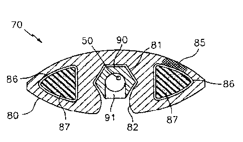
  • STRECKER, DAVID PHELPS (United States of America)
(73) Owners :
  • KEIR MANUFACTURING, INC.
(71) Applicants :
  • KEIR MANUFACTURING, INC. (United States of America)
(74) Agent: NORTON ROSE FULBRIGHT CANADA LLP/S.E.N.C.R.L., S.R.L.
(74) Associate agent:
(45) Issued: 2013-12-17
(86) PCT Filing Date: 2006-02-27
(87) Open to Public Inspection: 2006-09-08
Examination requested: 2011-02-14
Availability of licence: N/A
Dedicated to the Public: N/A
(25) Language of filing: English

Patent Cooperation Treaty (PCT): Yes
(86) PCT Filing Number: PCT/US2006/007369
(87) International Publication Number: US2006007369
(85) National Entry: 2007-08-23

(30) Application Priority Data:
Application No. Country/Territory Date
11/155,073 (United States of America) 2005-06-17
60/657,998 (United States of America) 2005-03-02

Abstracts

English Abstract


Disclosed herein is a flyer bow (10) for use in a wire-twisting machine
including a body with an airfoil shaped (70) cross section, a recessed channel
(81) within the body and a series of wire guide inserts (91) retained within
the recessed channel. Further disclosed herein is a wire guide insert
including a tubular body having an exterior non-circular shape corresponding
to a similar non-circular shape of a channel and an exhaust opening in the
wire guide inserts.


French Abstract

La balustre à broche (10) de l'invention est à utiliser dans une machine à torsader comprenant un corps avec un profil aérodynamique (70), un canal en creux (81) dans le corps et une série de dispositifs de guide-fil (91) retenus dans le canal en creux. L'invention concerne également un dispositif de guide-fil comprenant un corps tubulaire possédant une forme extérieure non circulaire correspondant à une forme non circulaire similaire d'une rainure et d'une bouche de sortie d'air dans les dispositifs de guide-fil.

Claims

Note: Claims are shown in the official language in which they were submitted.

6
What is claimed is:
1. A flyer bow for use in a wire twisting machine comprising:
a body with an airfoil shaped cross section,
a recessed channel within the body,
a plurality of individual wire guide inserts retained within the recessed
channel;
wherein the plurality of individual wire guide inserts are contained within
the
recessed channel such that no portion of the wire guide inserts protrudes
beyond the
envelope defined by the airfoil shape of the body.
2. The flyer bow claimed in Claim 1 wherein:
the wire guide inserts are rotationally locked within the recessed channel by
the
matching of a non-circular shape of the wire guide insert to that of the
recessed channel.
3. The flyer bow claimed in Claim 2 wherein:
the non-circular shape of the wire guide inserts and recessed channel are
hexagonal.
4. The flyer bow claimed in Claim 2 wherein:
an opening in one side of the wire guide insert is aligned with the opening in
the
recessed channel to facilitate egress of contamination.
5. The flyer bow claimed in Claim 1 wherein:
the body is made of a composite material reinforced with carbon fibers.
6. The flyer bow claimed in Claim 5 wherein:
the carbon fibers are braided.

7
7. The flyer bow claimed in Claim 1 wherein:
a portion of the body is hollow.
8. The flyer bow claimed in Claim 1 wherein:
a portion of the body is made of a foamed material.
9. The flyer bow claimed in Claim 1 wherein:
the recessed channel includes channel openings formed in a bottom surface of
the
flyer bow, the channel openings being a plurality of separate, elongated
orifices aligned
with the recessed channel.
10. The flyer bow claimed in Claim 1 further comprising:
a locking member secured to the flyer bow and one of the wire guide inserts to
restrict motion of the wire guide insert within the channel.
11. A wire guide insert comprising:
a tubular body having an exterior non-circular shape taken along a cross-
section
of the tubular body perpendicular to the longitudinal axis of the tubular body
corresponding to a similar non-circular shape of a channel in a flyer bow,
an exhaust opening in the wire guide inserts.
12. A wire guide insert claimed in claim 11 wherein:
the non circular shape of the wire guide insert is hexagonal.
13. A wire guide insert claimed in claim 11 wherein:
the interior surface of the wire guide is undulating.

Description

Note: Descriptions are shown in the official language in which they were submitted.


CA 02599042 2013-05-01
1
FLYER BOW WITH SEMI-ENCLOSED WIRE GUIDES
BACKGROUND
[0001] This invention relates to flyer bows. Flyer bows for use on twisting
machines
are well known in the art. Twisting machines with flyer bows can be used to
make
twisted cables for a wide variety of uses. Flyer bows can be used with
pairing, tripling,
quadding, bunching and twisted machines for wires. A typical flyer bow is
generally
rectangular in cross section. Wires to be twisted pass longitudinally along
the inside
surface of the flyer bow and are guided along the surface through ceramic or
metal wire
guides. A groove or recessed channel in the inside surface of the flyer bow is
often
incorporated into the design of the flyer bow in order to nest the wires to be
twisted close
to the surface of the flyer bow. This configuration reduces drag on the wires
due to wind
that sweeps transversely across the flyer bow during use. Flyer bows with
airfoil shapes
have been successfully used to increase speed of the winding machines with the
benefits
of minimum power draw and reduced operational noise. However, the airfoil does
little,
if anything, to minimize the effect of drag on the exposed wires. Furthermore,
the
exposed wire guides create additional drag on the flyer bow as it rotates.
[0002] An existing flyer bow is described in U.S. Patent No. 6,223,513 B1,
issued to
Post et al. and assigned to Kamatics Corporation. U.S. Patent No. 6,223,513 B1
discloses
a flyer bow with an integral enclosed wire guide. This design reduces drag by
incorporating the wire guide within the flyer bow.
BRIEF DESCRIPTION OF THE INVENTION (SUMMARY)
[0003] Disclosed herein is a flyer bow for use in a wire-twisting machine
including a
body with an airfoil shaped cross section, a recessed channel within the body
and a series
of wire guide inserts retained within the recessed channel.
[0004] Further disclosed herein is a wire guide insert including a tubular
body having
an exterior non-circular shape corresponding to a similar non-circular shape
of a channel
and an exhaust opening in the wire guide inserts.
[0005] According to a broad aspect of the present invention, there is provided
a flyer
bow for use in a wire twisting machine. The flyer bow comprises a body with an
airfoil
shaped cross section. A recessed channel is provided within the body. A
plurality of in
individual wire guide inserts are retained within the recessed channel. The
plurality of

CA 02599042 2013-05-01
,
2
individual wire guide inserts are contained within the recessed channel such
that no
portion of the wire guide inserts protrudes beyond the envelope defined by the
airfoil
shape of the body.
[0006] According to a further broad aspect of the present invention, there is
provided a
wire guide insert which comprises a tubular body having an exterior non-
circular shape
taken along a cross-section of the tubular body perpendicular to the
longitudinal axis of
the tubular body corresponding to a similar non-circular shape of a channel in
a flyer
bow. An exhaust opening in the wire guide inserts.
BRIEF DESCRIPTION OF THE DRAWINGS
[0007] Referring now to the drawings wherein like elements are numbered alike
in the
several Figures:
[0008] FIG. 1 is a front plan view of a conventional flyer bow.
[0009] FIG. 2 is a cross section view of the flyer bow of FIG.1 taken at
arrows 2-2.
[0010] FIG. 3 is a front plan view of a flyer bow depicting one embodiment of
the
invention.
[0011] FIG. 4 is a cross section view of the flyer bow of FIG. 3 taken at
arrows 4-4.
[0012] FIG. 5 is a cross section view of an alternate embodiment of the
invention
showing the wire guide insert in the hexagonal channel.
[0013] FIG. 6 is a bottom plan view of a hexagonal wire guide insert.
[0014] FIG. 7 is a front plan view of the wire guide insert of FIG. 6.
[0015] FIG. 8 is a section view of the wire guide insert of FIG. 7 taken at
arrows 8-8.
[0016] FIG. 9 is an alternate embodiment with corrugated bumps on the inside
diameter of the wire guide insert.
[0017] FIG.10 depicts deformation of conventional flyer bows compared to flyer
bows
in embodiments of the invention.
DETAILED DESCRIPTION
[0018] Referring to FIGS. 1 and 2, a conventional flyer bow 10 includes a body
20, the
wire guides 30 and the recessed channel 21. The recessed channel 21 and the
airfoil
shape of the body 20 illustrate conventional techniques incorporated to
minimize the

CA 02599042 2013-05-01
3
drag of the flyer bow 10 during operation of the twisting machine. Protrusion
of the wire
guides 30 outside the airfoil shape of the body 20 and into the air stream
result in higher
drag, less efficiency and more power consumption.
[0019] Referring to FIGS. 3 and 4, in one embodiment of the invention the
flyer bow
70 includes an aerodynamic airfoil shaped body 80 with a recessed hexagonal
shaped
channel 81, without the use of wire guides that protrude into the air stream
resulting in
higher aerodynamic losses. In tests conducted on wire twisting machines,
embodiments
of the invention consumed 12.3% less power than a conventional steel body with
exposed wire guides and 4.6% less power than a conventional composite airfoil
shaped
body with exposed wire guides. In addition to the extra power required to run
the
twisting machines (electric power costs) there was more noise.
[0020] Referring to FIG. 5, an alternate embodiment illustrates the use of
wire guide
inserts 90, that are retained completely within the airfoil shape of the body
80 in channel
81. The hexagonal shape of the insert 90 matches that of channel 81 to prevent
rotation
of the insert 90 within the channel 81, which maintains alignment of the
insert opening
91, as best depicted in FIGS. 7 and 8, with the channel opening 82. Both the
insert
opening 91 and the channel opening 82 allow for egress of dust that is created
by the
wire 50 passing through the wire guide inserts 90 during operation of the
twisting
machine. This feature provides for a self-cleaning design and provides for a
maintenance
free feature so that the twisting machine does not have to be shut down to
clear the dust
that could clog the channel in the bow.
[0021] Though a hexagonal shaped insert 90 and hexagonal channel 81 are
depicted in
this embodiment in FIG. 5, it should be understood that any non-circular
shaped cross
section that provides for anti-rotation of the insert 90 within the channel 81
(such as an
ellipse, square, pentagon, octagon, etc.) could adequately serve this function
without
deviating from the present invention.
[0022] The wire guide inserts 90 shown in FIGS. 6 through 8 are assembled into
channel 81 from either end of the body 80 in an end-to-end fashion. The wire
guide
inserts 90 abut each other along the channel 81 to maintain the position of
the wire guide
inserts 90 within the channel 81. The wire guide inserts 90 at the ends of the
body 80 are
secured in position by a retainer (not shown).

CA 02599042 2013-05-01
4
[0023] The wire guide inserts 90 can be constructed of any material that has a
hard,
wear resistant surface, to resist wear by the wire that passes through them. A
partial
material listing includes: steel, or steel that has had a surface plating or
coating applied to
it to increase the hardness such as titanium carbo-nitride (TiCN), titanium-
nitride (TiN),
electrolytic or electroless nickel plating, chrome plating, ceramic coatings,
etc. The insert
can also be made of nickel based alloys such as inconel, ceramic materials,
plastic
composites, etc.
[0024] The wire guide inserts 100 as shown in FIG. 9, can also be shaped with
an
undulating interior surface 101, that reduces the contact area with the wire
50 that passes
through the inserts 100, thereby decreasing the frictional forces and
resulting drag on the
wire.
[0025] The body 80, as shown in FIG. 5, can be constructed from composite
material
including but not limited to carbon fiber epoxy, fiberglass epoxy, aramid
fiber epoxy, or
a combination of two or three of the materials mentioned. The body 80 may be
reinforced with a carbon fiber 85 material using a braided structure for the
carbon fibers
85. The use of a braided fiber 85 construction is also unique as this type of
construction
increases the strength of the body 80 and allows the body 80 to have increased
damage
tolerance and increased resistance to fractures due to impacts from wire 50
strikes. The
wire 50 that passes through the wire twisting machine will at times break and
the broken
wire 50 can impact the body 80 which is rotating at a high speed in the
machine. The
braided fiber 85 construction is more resilient to wire 50 strikes and the
braided fiber 85
construction works to arrest any cracks that may be initiated due to a wire 50
strike
resulting in a longer body 80 life.
[0026] Referring again to FIG. 5, the body 80 of the bow may also have hollow
sections 86 to decrease the weight while increasing the stiffness and give it
an I-beam
geometric shape. The reduction of weight of the body 80 reduces the
centrifugal pull on
the airfoil body 80 attachment ends. The hollow sections 86 can also be filled
with foam
87 to further increase stiffness of the body 80 without adding significantly
to the weight
of the body 80. The thicker section that is provided by the use of an airfoil
section to
contain the wire guide inserts 90 and the wire 50 internally, also produces a
stiffer airfoil
cross section. This stiffer cross section enables the body to keep its as
manufactured
curved shape 120 even under the high centrifugal loads that are imposed on the
body
when it is spinning in the wire twisting machine as is depicted in FIG. 10.
Conventional

CA 02599042 2013-05-01
designs with thinner cross sections tend to produce an irregular shape 130 and
tend to
flatten at the apex of the bow while rotating. The result of the irregular
shape 130 is that
the wire makes greater contact with the wire guides and degrades the quality
of the wire
due to the abrasion by the greater contact area and force.
[0027] It is within the ambit of the present invention to cover any obvious
modifications, provided such modifications fall within the scope of the
appended claims.

Representative Drawing
A single figure which represents the drawing illustrating the invention.
Administrative Status

2024-08-01:As part of the Next Generation Patents (NGP) transition, the Canadian Patents Database (CPD) now contains a more detailed Event History, which replicates the Event Log of our new back-office solution.

Please note that "Inactive:" events refers to events no longer in use in our new back-office solution.

For a clearer understanding of the status of the application/patent presented on this page, the site Disclaimer , as well as the definitions for Patent , Event History , Maintenance Fee  and Payment History  should be consulted.

Event History

Description Date
Common Representative Appointed 2019-10-30
Grant by Issuance 2013-12-17
Inactive: Cover page published 2013-12-16
Inactive: Final fee received 2013-10-01
Pre-grant 2013-10-01
Letter Sent 2013-06-26
Notice of Allowance is Issued 2013-06-26
Inactive: Approved for allowance (AFA) 2013-06-20
Amendment Received - Voluntary Amendment 2013-05-01
Inactive: S.30(2) Rules - Examiner requisition 2012-11-01
Amendment Received - Voluntary Amendment 2011-07-07
Inactive: Correspondence - Transfer 2011-05-06
Letter Sent 2011-04-18
Inactive: Single transfer 2011-03-25
Letter Sent 2011-03-04
Request for Examination Received 2011-02-14
Request for Examination Requirements Determined Compliant 2011-02-14
All Requirements for Examination Determined Compliant 2011-02-14
Request for Examination Received 2011-02-14
Letter Sent 2008-08-11
Inactive: Single transfer 2008-05-13
Inactive: Cover page published 2007-11-15
Inactive: Notice - National entry - No RFE 2007-11-13
Inactive: First IPC assigned 2007-09-28
Application Received - PCT 2007-09-27
National Entry Requirements Determined Compliant 2007-08-23
Application Published (Open to Public Inspection) 2006-09-08

Abandonment History

There is no abandonment history.

Maintenance Fee

The last payment was received on 2013-02-04

Note : If the full payment has not been received on or before the date indicated, a further fee may be required which may be one of the following

  • the reinstatement fee;
  • the late payment fee; or
  • additional fee to reverse deemed expiry.

Patent fees are adjusted on the 1st of January every year. The amounts above are the current amounts if received by December 31 of the current year.
Please refer to the CIPO Patent Fees web page to see all current fee amounts.

Owners on Record

Note: Records showing the ownership history in alphabetical order.

Current Owners on Record
KEIR MANUFACTURING, INC.
Past Owners on Record
DAVID PHELPS STRECKER
DOUGLAS ALLAN VOGE
SCOTT SCRANTON
Past Owners that do not appear in the "Owners on Record" listing will appear in other documentation within the application.
Documents

To view selected files, please enter reCAPTCHA code :


To view images, click a link in the Document Description column. To download the documents, select one or more checkboxes in the first column and then click the "Download Selected in PDF format (Zip Archive)" or the "Download Selected as Single PDF" button.

List of published and non-published patent-specific documents on the CPD .

If you have any difficulty accessing content, you can call the Client Service Centre at 1-866-997-1936 or send them an e-mail at CIPO Client Service Centre.


Document
Description 
Date
(yyyy-mm-dd) 
Number of pages   Size of Image (KB) 
Description 2007-08-22 6 296
Drawings 2007-08-22 8 111
Representative drawing 2007-08-22 1 9
Abstract 2007-08-22 1 66
Claims 2007-08-22 2 60
Description 2013-04-30 5 238
Claims 2013-04-30 2 56
Drawings 2013-04-30 3 53
Representative drawing 2013-11-17 1 17
Maintenance fee payment 2024-02-22 47 1,942
Notice of National Entry 2007-11-12 1 195
Courtesy - Certificate of registration (related document(s)) 2008-08-10 1 104
Reminder - Request for Examination 2010-10-27 1 126
Acknowledgement of Request for Examination 2011-03-03 1 176
Courtesy - Certificate of registration (related document(s)) 2011-04-17 1 104
Courtesy - Certificate of registration (related document(s)) 2011-04-17 1 103
Commissioner's Notice - Application Found Allowable 2013-06-25 1 164
PCT 2007-08-22 1 50
Correspondence 2007-11-12 1 24
Correspondence 2013-09-30 2 66