Language selection

Search

Patent 2599135 Summary

Third-party information liability

Some of the information on this Web page has been provided by external sources. The Government of Canada is not responsible for the accuracy, reliability or currency of the information supplied by external sources. Users wishing to rely upon this information should consult directly with the source of the information. Content provided by external sources is not subject to official languages, privacy and accessibility requirements.

Claims and Abstract availability

Any discrepancies in the text and image of the Claims and Abstract are due to differing posting times. Text of the Claims and Abstract are posted:

  • At the time the application is open to public inspection;
  • At the time of issue of the patent (grant).
(12) Patent: (11) CA 2599135
(54) English Title: PIPE TENSIONER MACHINE
(54) French Title: MACHINE A TENDRE LES CONDUITES
Status: Expired and beyond the Period of Reversal
Bibliographic Data
(51) International Patent Classification (IPC):
  • F16L 01/23 (2006.01)
(72) Inventors :
  • DIEHL, OTTMAR (Thailand)
(73) Owners :
  • OTTMAR DIEHL
(71) Applicants :
  • OTTMAR DIEHL (Thailand)
(74) Agent: PERLEY-ROBERTSON, HILL & MCDOUGALL LLP
(74) Associate agent:
(45) Issued: 2013-05-28
(86) PCT Filing Date: 2006-02-10
(87) Open to Public Inspection: 2006-09-28
Examination requested: 2010-12-20
Availability of licence: N/A
Dedicated to the Public: N/A
(25) Language of filing: English

Patent Cooperation Treaty (PCT): Yes
(86) PCT Filing Number: PCT/EP2006/001250
(87) International Publication Number: EP2006001250
(85) National Entry: 2007-08-24

(30) Application Priority Data:
Application No. Country/Territory Date
05006152.2 (European Patent Office (EPO)) 2005-03-21

Abstracts

English Abstract


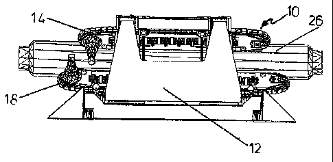
A pipe tensioner machine for offshore pipelaying operations comprises
adjustable squeeze elements for the transfer of tension to the pipe string.
Four tension banks (14, 16, 18, 20) are provided in an angle of substantially
90~ to each other mounted inside a framework (12). The tension banks are
movable along guides. The tension banks (14, 16, 18, 20) comprise revolving
tracks (22) carrying traction pads (24) transmitting the squeeze force to the
pipe (26). The lower tension banks (18, 20) are longer than the upper tension
banks (14, 16).


French Abstract

La présente invention concerne une machine à tendre les conduites pour les opérations de pose de conduites en mer comprenant des éléments de serrage ajustables pour transmettre la tension à la colonne de conduites. Quatre bancs de tensionnage (14, 16, 18, 20) sont prévus avec un angle sensiblement de 90° les uns par rapport aux autres et montés à l'intérieur d'un châssis (12). Les bancs de tensionnage peuvent être déplacés le long de guides. Les bancs de tensionnage (14, 16, 18, 20) comprennent des pistes d'inversion (22) supportant des coussins de traction (24) transmettant la force de serrage à la conduite (26). Les bancs de tensionnage (18, 20) inférieurs sont plus longs que les bancs de tensionnage (14, 16) supérieurs.

Claims

Note: Claims are shown in the official language in which they were submitted.


CLAIMS
1. Pipe tensioner machine (10) for offshore pipe laying operations comprising
squeeze elements (14, 16, 18, 20) for transferring tension forces to the pipe
string (26) as well as a driving structure for the squeeze elements where
two top squeeze tracks (14, 16) and two bottom squeeze tracks (18, 20)
are provided which may be moved relative to each other by an adjustment
device mounted within a frame structure,
characterized in that the two bottom squeeze tracks (18, 20) are longer
than the two top squeeze tracks (14, 16) and that the two top squeeze
tracks (14, 16) slide up and down on guides in form of a narrow "V' with
45 degree in between the legs of the "V' and the bottom squeeze tracks
(18, 20) slide up and down on guides in the form of a wide "V' with 135
degree in between the legs of the "V'.
2. Pipe tensioner machine (10) according to claim 1, characterized in that the
track length between a centre drive sprocket and an idler sprocket is fully en-

gaged with the pipe.
3. Pipe tensioner machine (10) according to claim 1 or 2, characterized in
that air springs are arranged for providing at least a substantial part of the
squeeze force.
4. Pipe tensioner machine (10) according to any of claims 1 to 3,
characterized in that hydraulic jacks are provided for supporting the ma-
chine during operation.
5. Pipe tensioner machine (10) according to claim 4, characterized in that
four hydraulic jacks are provided for supporting the machine.
6

6. Pipe tensioner machine (10) according to any of claims 1 to 5,
characterized in that two bottom tension banks are sliding on planes
with a 22.5° angle between horizontal.
7. Pipe tensioner machine (10) according to any of claims 1 to 6,
characterized in that two top tension banks are sliding on planes with a
22.5° angle between vertical.
8. Pipe tensioner machine (10) according to any of claims 1 to 7,
characterized by hydraulic cylinders pushing two top tension banks
against the pipe.
9. Pipe tensioner machine (10) according to claim 8, characterized in said
cylinders being tilted in a forward direction.
7

Description

Note: Descriptions are shown in the official language in which they were submitted.


CA 02599135 2007-08-24
WO 2006/099917 PCT/EP2006/001250
Pipe Tensioner Machine
Field of the Invention
lo The present invention relates to a pipe tensioner machine for maintaining a
predetermined tension of the pipe string between the pipe laybarge and
seafloor
during offshore pipelay operation. In offshore pipelaying operations the pipe
string
between the laybarge and seafloor has to be kept taut to prevent overdue
stress
and buckling. The tension has to be maintained during all barge movements. For
processing the pipe aboard the laybarge, the pipe string has to be kept
steady,
which means the pipe tension has to be kept within certain limits to
compensate
for the various sea conditions. The pipe string is squeezed between track
loops or
wheels which are propelled and controlled automatically.
Background of the Invention
From EP 0 296 272 Al there is known a pipe tensioner machine for offshore pipe
laying operations comprising squeeze elements for transferring tension forces
to
the pipes as well as a driving structure for the squeeze elements where two
top
squeeze and two bottom squeeze tracks are provided which may be moved
relative to each other by an adjustment device mounted within a frame
structure.
Although this device operates properly it does not take account of the fact
that due
to the weight of the pipe more drive torque can be applied on the bottom
tracks,
and further, that the top of the machine is obstructed and no protrusions,
like valve
stems, in the pipe string can passe.
Other pipe tensioner machines (SAS Gouda by) use two opposing clamping tracks
which are arranged either in horizontal or vertical direction. These machines
squeeze, however, the cross section of the pipe string oval which is due to
the 180
degree opposed squeeze force.

CA 02599135 2012-12-27
A further 4 track type of tensioner machines (Remacut) is only suited for
small
pipe string diameters. Therefore, there is a long felt and unmet need for a
more effective pipe tensioner machine overcoming the before mentioned
disadvantages and short comings which is adaptable to very different pipe
diameters transmitting a controlled squeeze force on the pipe string.
Summary of the Invention
The problem is solved according to the present invention. With respect to
further preferred embodiments of the invention reference is made to the
features of the subclaims. In accordance with the present invention the two
bottom squeeze tracks are longer than the two top squeeze tracks. Thus,
more drive can be provided on the bottom tracks. A further favourable feature
of the invention is that the track length between centre drive sprocket and
idler sprocket is fully engaged with the pipe. Air springs may be arranged for
providing at least a substantial part of the squeeze force. In accordance with
a preferred embodiment four hydraulic jacks are provided for supporting the
machine. In accordance with a preferred embodiment of the invention two
bottom tension banks are sliding on planes with a 22.5 angle between
horizontal. In accordance with this embodiment two top tension banks are
sliding on planes with a 22.5 angle between vertical. Favourably hydraulic
cylinders push the two top tension banks against the pipe. According to a
most preferred embodiment of the present invention these cylinders are tilted
in a forward direction. According to the invention the two top traction banks
slide up and down on a narrow "V" with preferable 45 degree in between the
legs of the "V". The two bottom traction banks slide on a wide "V" with
preferable 135 degrees in between. Nevertheless the invention is not limited
to these values and all other angles may be suited.
Brief Description of the Drawings
The accompanying drawings which form a part of the specification illustrate
several key embodiments of the present invention. The drawings and des
description together serve to fully explain the invention. In the drawings:
-2-

CA 02599135 2007-08-24
WO 2006/099917 3 PCT/EP2006/001250
Fig. 1 is a perspective view of the pipe tensioner machine according to the
present invention handling a 60 " diameter pipe,
Fig. 2 is a side view of the machine depicted in Fig. 1,
Fig. 3 is a front view of the machine depicted in Fig. 1,
Fig. 4 is a perspective view of a pipe tensioner machine according to the
present invention handling an 8" diameter pipe,
Fig. 5 is a side view of the machine depicted in Fig. 4,
Fig. 6 a front view of the machine depicted in Fig. 4 and
Fig. 7 is a perspective view of a part of a track chain with pads according to
the present invention.
Detailed Description of the Preferred Embodiments
Referring now to the drawings were like numerals denote like elements Figs. 1
to 3
show a pipe tensioner machine according to the invention which is in general
identified by reference numeral 10. Within a frame work 12 there are mounted
two
upper tension banks 14, 16 and two lower tension banks 18, 20. The tension
banks include revolving track chains 22 provided with traction pads 24 for
engagement with the pipe 26 to be handled (see Fig. 7). As may be taken from
the
drawings the two bottom tracks 18, 20 are longer than the top tracks 14, 16 to
utilize the pipe weight for additional traction.
Referring now to Figs. 4 to 6 the same show a pipe tensioner machine 10
handling
an 8 " diameter pipe string 26. The same as with the tensioner machine
depicted
in Figs. 1 to 3 there is also a framework 12 for mounting the two upper
tension
banks 14, 16 as well as the two lower tension banks 18, 20.

WO 2006/099917 CA 02599135 2007-
08-244 PCT/EP2006/001250
As mentioned before the two bottom tracks 18, 20 are longer than the two top
tracks 14, 16 to utilize the pipe weight for traction. 30 tons pipe weight for
instance
translate into 15 tons (30 kips) more tension. The bottom tracks 18, 20
therefore
provide more drive torque. Furthermore, interference of the drive motors is
avoided. The track length between centre drive sprocket and centre idler
sprocket
is fully engaged with the pipe 26.
The machine can adapt to any pipe string angle in the overbend region, i.e.
the
machine can be used at the end of the production line. 15 % of the squeeze
force
per track are provided by the drive sprocket with the adjacent track roller
and the
idler sprocket with the adjacent track roller. Said sprockets and rollers also
do the
guiding of the tension banks relative to the pipe. Air springs provide the
remaining
85 % squeeze.
When laying stiff pipe the machine, which is supported by four hydraulic
jacks, will
adapt the two bottom tension banks 18, 20 to the pipe string. When laying
light
pipe the machine can be locked in place to suite the present overbend and let
the
pipe string adapt to the machine.
The two bottom tension banks 18, 20 are sliding on planes with a 22.5 angle
between horizontal thus maintaining for any pipe diameter a constant bottom of
pipe distance. During operation those two banks are fixed in place. The two
top
tension banks 14, 16 are sliding on planes with a 22.5 angle between vertical
thus
guaranteeing at each pipe diameter symmetry and a 90 spaced pipe squeeze.
The two top tension banks 14, 16 are sliding in their guides and are pushed
against the pipe by hydraulic cylinders thus making up for differences in pipe
string
diameter and providing squeeze. Said hydraulic cylinders are reacting against
a
strong back which is moved up and down by jack screws. Said cylinders are
tilted
forward to take the tension load from the slides.
Valve stamps protruding from the top of the pipeline or flow meter connections
protruding from the side of the pipeline can pass the machine under full
tension.
When laying pipe down in "S" configuration the two top banks 14, 16 are moved

CA 02599135 2012-12-27
further up to make room for the pulling head which lifts off due to lack of
weight. Under 8" pipe diameter two opposing tension banks are used while
remaining two tension banks are locked and carry guide rollers. The tensioner
machine is changed over to a different pipe diameter in a very short time. Low
track tension is needed to keep pads 24 engaged with pipe string, since the
distance between the center of track pin and the contact area of traction pad
24 is as narrow as possible, and therefore wear and tear on track pins is low.
The traction pads 24 have transverse play to facilitate moving outwardly while
the track is engaged in the radius portion of the pipe string overbend. The
two
top guides could be described as a narrow "V" and bottom guides as a wide
iv,.
-5-

Representative Drawing
A single figure which represents the drawing illustrating the invention.
Administrative Status

2024-08-01:As part of the Next Generation Patents (NGP) transition, the Canadian Patents Database (CPD) now contains a more detailed Event History, which replicates the Event Log of our new back-office solution.

Please note that "Inactive:" events refers to events no longer in use in our new back-office solution.

For a clearer understanding of the status of the application/patent presented on this page, the site Disclaimer , as well as the definitions for Patent , Event History , Maintenance Fee  and Payment History  should be consulted.

Event History

Description Date
Time Limit for Reversal Expired 2017-02-10
Letter Sent 2016-02-10
Inactive: Cover page published 2013-05-28
Grant by Issuance 2013-05-28
Inactive: Final fee received 2013-03-07
Pre-grant 2013-03-07
Notice of Allowance is Issued 2013-02-04
Letter Sent 2013-02-04
Notice of Allowance is Issued 2013-02-04
Inactive: Approved for allowance (AFA) 2013-01-27
Amendment Received - Voluntary Amendment 2012-12-27
Inactive: S.30(2) Rules - Examiner requisition 2012-08-14
Amendment Received - Voluntary Amendment 2012-04-24
Letter Sent 2011-01-10
Request for Examination Requirements Determined Compliant 2010-12-20
All Requirements for Examination Determined Compliant 2010-12-20
Request for Examination Received 2010-12-20
Inactive: Office letter 2009-11-10
Inactive: IPRP received 2008-03-06
Inactive: Cover page published 2007-11-15
Inactive: Notice - National entry - No RFE 2007-11-13
Inactive: Inventor deleted 2007-11-13
Inactive: First IPC assigned 2007-09-28
Application Received - PCT 2007-09-27
National Entry Requirements Determined Compliant 2007-08-24
Small Entity Declaration Determined Compliant 2007-08-24
Application Published (Open to Public Inspection) 2006-09-28

Abandonment History

There is no abandonment history.

Maintenance Fee

The last payment was received on 2013-01-18

Note : If the full payment has not been received on or before the date indicated, a further fee may be required which may be one of the following

  • the reinstatement fee;
  • the late payment fee; or
  • additional fee to reverse deemed expiry.

Patent fees are adjusted on the 1st of January every year. The amounts above are the current amounts if received by December 31 of the current year.
Please refer to the CIPO Patent Fees web page to see all current fee amounts.

Fee History

Fee Type Anniversary Year Due Date Paid Date
Basic national fee - small 2007-08-24
MF (application, 2nd anniv.) - small 02 2008-02-11 2008-01-22
MF (application, 3rd anniv.) - small 03 2009-02-10 2009-01-21
MF (application, 4th anniv.) - small 04 2010-02-10 2010-02-03
Request for examination - small 2010-12-20
MF (application, 5th anniv.) - small 05 2011-02-10 2011-01-18
MF (application, 6th anniv.) - small 06 2012-02-10 2012-01-18
MF (application, 7th anniv.) - small 07 2013-02-11 2013-01-18
Final fee - small 2013-03-07
MF (patent, 8th anniv.) - small 2014-02-10 2014-02-10
MF (patent, 9th anniv.) - small 2015-02-10 2015-02-09
Owners on Record

Note: Records showing the ownership history in alphabetical order.

Current Owners on Record
OTTMAR DIEHL
Past Owners on Record
None
Past Owners that do not appear in the "Owners on Record" listing will appear in other documentation within the application.
Documents

To view selected files, please enter reCAPTCHA code :


To view images, click a link in the Document Description column. To download the documents, select one or more checkboxes in the first column and then click the "Download Selected in PDF format (Zip Archive)" or the "Download Selected as Single PDF" button.

List of published and non-published patent-specific documents on the CPD .

If you have any difficulty accessing content, you can call the Client Service Centre at 1-866-997-1936 or send them an e-mail at CIPO Client Service Centre.


Document
Description 
Date
(yyyy-mm-dd) 
Number of pages   Size of Image (KB) 
Abstract 2007-08-23 1 61
Claims 2007-08-23 2 50
Description 2007-08-23 5 223
Drawings 2007-08-23 2 94
Representative drawing 2007-08-23 1 14
Claims 2012-04-23 2 50
Description 2012-12-26 5 208
Claims 2012-12-26 2 49
Representative drawing 2013-05-27 1 14
Reminder of maintenance fee due 2007-11-12 1 113
Notice of National Entry 2007-11-12 1 195
Reminder - Request for Examination 2010-10-12 1 118
Acknowledgement of Request for Examination 2011-01-09 1 178
Commissioner's Notice - Application Found Allowable 2013-02-03 1 162
Maintenance Fee Notice 2016-03-22 1 169
Fees 2012-01-17 1 156
Fees 2013-01-17 1 156
PCT 2007-08-23 4 124
PCT 2007-08-24 6 219
Fees 2008-01-21 1 25
Fees 2009-01-20 1 29
Correspondence 2009-11-09 1 23
Fees 2010-02-02 1 200
Fees 2011-01-17 1 202
Correspondence 2013-03-06 1 27