Note: Descriptions are shown in the official language in which they were submitted.
CA 02599317 2007-08-27
- 1 -
DESCRIPTION
CIGARETTE MAKING APPARATUS
Technical Field
This invention relates to a cigarette making apparatus
for manufacturing cigarettes by applying a flavoring
material to a wrapping-paper web continuously supplied to a
wrapping machine.
Background Art
A wrapping machine used in manufacture of cigarettes
is presented in detail in published U.S. Patent Application
No. 2004/0118416 Al, for example. In this wrapping machine,
a wrapping-paper web continuously supplied is supported and
conveyed lengthways by a garniture tape, and on the upper
side of this wrapping-paper web, a controlled amount of
shredded tobacco is disposed. Then, by continuously
wrapping the shredded tobacco in the wrapping-paper web by
bending both sides of the wrapping-paper web, a continuous
tobacco rod is continuously formed. During this process,
seam glue for sticking together the opposite side ends of
the wrapping-paper web wrapped around the shredded tobacco
is applied to one side end of the wrapping-paper web
continuously supplied to the wrapping machine.
International Patent Publication No. 2004/064546
discloses application of a flavoring material for
suppressing a particular smell of cigarettes without
harming the taste thereof, to a wrapping-paper web. The
Jv fiavoriijg 1Tiateriai Of tjils type is, for exarClpie, a liquid
prepared by dissolving a flavoring substance in a CMC
(carboxymethylcellulose) aqueous solution or a benzine
alcohol suspension. The amount of the flavoring material
CA 02599317 2007-08-27
- 2 -
applied to the wrapping-paper web is great, compared with
the seam glue. Further, the amount of the flavoring
material applied to the wrapping-paper web affects the
quality of the cigarettes manufactured. Thus, it is
necessary to control the amount of the flavoring material
applied, accurately.
Meanwhile, the speed of supply of the wrapping-paper
web to the wrapping machine is varied depending on the
operating speed of the wrapping machine, namely the speed
at which the wrapping machine forms a continuous tobacco
rod. Thus, when the flavoring material is applied to the
wrapping-paper web while the continuous tobacco rod is
being formed, it is important to adjust the rate of supply
of the flavoring material to an application nozzle
depending on the traveling speed of the wrapping-paper web
(speed of supply of the wrapping-paper web) so that the
flavoring material will be applied to the wrapping-paper
web in a fixed amount per unit area. There is, however,
observed a problem that although the operation of a pump
for supplying the flavoring material to the flavoring-
material application nozzle is controlled depending on the
speed of supply of the wrapping-paper web so that the
flavoring material will be applied to the wrapping-paper
web in a fixed amount per unit area, the amount per unit
area of the flavoring material applied to the wrapping-
paper web gradually increases.
Disclosure of the Invention
The primary object of this invention is to provide a
U-igaLeLLe rnakirrg apparatus which can aiways and stably
apply a flavoring material to a wrapping-paper web
continuously supplied to a wrapping machine, in a fixed
amount per unit area, thereby stabilizing the quality of
CA 02599317 2007-08-27
- 3 -
cigarettes manufactured.
Investigating the cause of the phenomenon in the
conventional apparatus that although the rate of supply of
the flavoring material is controlled depending on the speed
of supply of the wrapping-paper web, the amount per unit
area of the flavoring material applied to the wrapping-
paper web gradually increases, the inventors have found out
that this phenomenon is exclusively due to the reason that
a rise in machine temperature during the operation of the
cigarette making apparatus causes a rise in temperature of
the flavoring material, which results in a decrease in
viscosity of the flavoring material. The present invention
therefore pays attention to the viscosity of the flavoring
material. Specifically, the present invention keeps the
flavoring material at a fixed viscosity, thereby enabling
the flavoring material to be applied to the wrapping-paper
web in a fixed amount per unit area only by controlling the
rate of supply of the flavoring material depending on the
rate of supply of the wrapping-paper web.
The present invention provides a cigarette making
apparatus comprising a wrapping machine for continuously
wrapping shredded tobacco in a wrapping-paper web by
bending both sides of the wrapping-paper web; and a
flavoring-material application device for applying a
flavoring material to the wrapping-paper web, provided in a
path along which the wrapping-paper web is supplied to the
wrapping machine, as a stage prior to applying seam glue,
wherein
the flavoring-material application device includes, in
~v auU~L-Lon to an application nozzle lor dpplying the
flavoring material to the wrapping-paper web and a pump
driven to rotate to supply the flavoring material to the
application nozzle, a cooling-water passage which allows a
CA 02599317 2007-08-27
- 4 -
coolant to circulate along a flavoring-material supply
passage through which the flavoring material is supplied by
the pump, thereby cooling the flavoring material, and a
cooling unit for controlling the temperature of the coolant
supplied to the cooling-water passage.
Specifically, in the present invention, a cooling-
water passage is provided along a flavoring-material supply
pipe (flavoring-material supply passage) through which a
flavoring material is supplied from a flavoring-material
tank to an application nozzle by means of a pump, so that
the flavoring material can be cooled by a coolant (cooling
water) flowing through the cooling-water passage, and also
a cooling unit for controlling the temperature of the
coolant (cooling water) is provided. Since the temperature
of the flavoring material is fixed in spite of variations
in machine temperature because of the provision of this
cooling-water passage, the amount per unit area of the
flavoring material applied to the wrapping-paper web is
fixed only by controlling the rate of supply of the
flavoring material depending on the rate of supply of the
wrapping-paper web.
In the cigarette making apparatus arranged as
described above, since the temperature of the flavoring
material can be controlled by means of the cooing water
passage which is controlled in temperature by the cooling
unit, the flavoring material supplied to the application
nozzle can be kept at a fixed temperature in spite of
variations in machine temperature. Consequently,
variations in viscosity of the flavoring material are
~n '' '_ty = , ,
JV JUppresJeU, so l,lldl, l i.l'1C 11aVVI1111 ltldl.Cr1d1 d~Jp11'L''U l.U Llle
wrapping-paper web by the application nozzle can be easily
controlled to a fixed amount per unit area only by
controlling the drive of the pump. Since the flavoring
CA 02599317 2009-04-17
material is kept at a fixed temperature and therefore the
amount per unit area of the flavoring material can be
stably controlled only by contr-olling the drive of the pump,
the quality of cigarettes manufactured can be maintained
easily and stably.
Desirably, the cooling unit should include a first
control system for detecting the temperature of the coolant
supplied to the cooling-water passage and controlling the
temperature of the coolant on the basis of the detected
temperature of the coolant, and a second control system for
detecting the temperature of the flavoring material
supplied to the application nozzle and controlling the
temperature of the coolant on the basis of the detected
temperature of the flavoring material. In this case, the
cooling unit performs drive coritrol by activating the first
control system while the wrapping machine is at rest, and
activating the second control system while the wrapping
machine is operating.
According to a preferred aspect, the invention relates to a cigarette making
apparatus as defined hereinabove, wherein:
the first control system detects the temperature of the coolant by means of a
first sensor provided to the cooling unit, and the second control system
detects the
temperature of the flavoring material by means of a second sensor incorporated
in
the application nozzle.
By controlling the temperature of the coolant by
selecting between the control systems depending on the
operating state of the cigarette making apparatus, the
cooling unit can stably and efficiently control the
flavoring material to a fixed temperature, with a burden
reduced.
CA 02599317 2009-04-17
6
In one aspect, the cooling-water passage includes a
coolant passage pipe which surrounds the outside of the
flavoring-material supply pipe to form a double-pipe
structure, and is used for the coolant to flow from the
application-nozzle side to the pump side. This structure
t... . t~ ' ' .. r t . t_
lilanCJ 1L pVSS11J1e LV L11{ the LCIIIJCidtuLe of ~Ile flavoring
material in the application nozzle, which directly affects
the amount per unit area of the flavoring material applied,
and also reduce a rise in temperature of the flavoring
material before supplied to the application nozzle, by
utilizing the excess capacity (cooling capacity) of the
coolant. This can increase the efficiency of cooling the
flavoring material.
The flavoring material is, for example a liquid
prepared by dissolving powder containing a flavoring
substance in a CMC (carboxymethylcellulose) aqueous
solution or with a benzine alcohol suspension.
Brief Description of the Drawings
[FIG. 1] A diagram showing schematic structure of an
embodiment of cigarette making apparatus according to the
present invention.
[FIG. 2] A diagram showing schematic structure of a
flavoring-material application device incorporated in the
cigarette making apparatus shown in FIG. 1.
[FIG. 3] A diagram showing an example of a cooling
control process performed in the flavoring-material
application device shown in FIG. 2.
CA 02599317 2009-04-17
6a
[FIG. 4] A diagram showing how the temperature of a
flavoring material and the rate of discharge of the
flavoring material from an application nozzle vary with
time, when the cigarette making apparatus operates without
utilizing a cooling-water passage.
[FIG. 5] A diagram showing how the temperature of the
flavoring material and the rate of discharge of the
flavoring material from the application nozzle vary with
time, when the cigarette making apparatus operates keeping
the coolant at a fixed temperature.
[FIG. b] A diagram showing how the temperature ot the
flavoring material and the rate of discharge of the
flavoring material from the application nozzle vary with
time, when the cigarette making apparatus operates keeping
CA 02599317 2007-08-27
- 7 -
the flavoring material at a fixed temperature.
Best Mode of Carrying out the Invention
Referring to the drawings, an embodiment of cigarette
making apparatus according to the present invention will be
described below.
FIG. 1 shows a schematic structure of a cigarette
making apparatus. A roll 11 of a wrapping-paper web W of a
determined width is provided to the cigarette making
apparatus so that the wrapping-paper web W is fed from the
roll 11 along a feed path 12. The feed path 12 is defined
by a plurality of guide rollers 13, and the terminal end of
the feed path 12 is adjacent to the entry of a wrapping
machine 20. The feed path 12 includes feed rollers (not
shown) and a reservoir 13. The reservoir 13 is provided
for "buffering", namely storing a determined length of the
wrapping-paper web W to give time for joining a wrapping-
paper web W of a subsequent roll 11 to the previous
wrapping-paper web W.
The wrapping machine 20 includes an endless garniture
tape 21. The wrapping-paper web W is fed from the terminal
end of the feed path 12 to the garniture tape 21,
continuously. The garniture tape 21 is passed around a
drive drum 22 to form a round path. As the drive drum 22
rotates, the garniture tape travels with the wrapping-paper
web W, in a forming groove (not shown) in a forming bed 23,
in one direction. The forming groove in the forming bed 23
has a shape such that it gradually decreases in width and
radius of curvature of the bottom, from the entry to the
exit of the wrapping machine 20, and has an approximately
half-round cross-section at the exit of the wrapping
machine 20.
At the entry of the wrapping machine 20, shredded
CA 02599317 2007-08-27
- 8 -
tobacco K is supplied onto the upper side of the wrapping-
paper web W. More specifically, shredded tobacco K is
sucked onto the lower side of an endless tobacco band 24 to
form a shredded tobacco layer KL, which is conveyed to the
entry of the wrapping machine 20 as the tobacco band 24
travels. The shredded tobacco layer KL retained on the
tobacco band 24 by suction is taken off the tobacco band 24
and transferred onto the wrapping-paper web W by a tong
shoe 25 disposed at the entry of the wrapping machine 20.
After the shredded tobacco layer KL is supplied onto
the wrapping-paper web W in this manner, the wrapping-paper
web W with the shredded tobacco layer KL on is conveyed
into the wrapping machine 10, and passes through the tong
shoe 25, a short holder 26, a glue application nozzle 27
and a long holder 28, which are provided in the wrapping
machine 10, successively. In this process, the shredded
tobacco K is wrapped in the wrapping-paper web W so that a
continuous tobacco rod TR is formed continuously. The
tobacco rod TR formed is sent out from the exit of the
wrapping machine 10.
More specifically, the tong shoe 25 compresses the
shredded tobacco layer KL from above, thereby forming it to
describe an arc in cross-section, while the forming groove
in the forming bed 23 bends the wrapping-paper web W into a
U-like cross-section, from below, with the garniture tape
21. Thus, the shredded tobacco layer KL is compressed from
above and from below, and thereby formed to describe upper
and lower arcs in cross-section. The short holder 26 bends
one side of the wrapping-paper web W into an arc, with the
garniture tape 21, so that one half of the upper half of
the shredded tobacco layer KL is covered with this part of
the wrapping-paper web. At this time, the glue application
nozzle 27 applies seam glue to the other side end of the
CA 02599317 2007-08-27
- 9 -
wrapping-paper web W. Then, the long holder 28 bends this
other side of the wrapping-paper web W into an arc, with
the garniture tape 21, so that the other half of the upper
half of the shredded tobacco layer KL is covered with this
part of the wrapping-paper web W. Consequently, one side
end of the wrapping-paper web W comes on the other side end
and they are stuck together by the seam glue, so that the
tobacco rod TR is formed.
The tobacco rod TR sent out from the exit of the
wrapping machine 20 passes under a heater 29, where the
seam glue is dried. Then, the tobacco rod TR is cut by a
rotary knife 31 in a cutting section, into cigarette rods
SR of a determined length, namely twice the length of a
cigarette. The cigarette rods SR are supplied to the next
stage (next step), namely a filter attachment machine (not
shown) by a kicker 32.
In the filter attachment machine, one cigarette rod SR
is cut into two cigarettes, and a filter plug is disposed
between the two cigarettes, coaxially. Then a tip paper
piece is wrapped around them to cover the filter plug and
the adjacent ends of the cigarettes, so that the two
cigarettes and filter plug are joined together to form a
double filter-cigarette. Then, by cutting the double
filter-cigarette at the center of the filter plug, into two
equal parts, two filtered cigarettes are formed.
In the cigarette making apparatus basically having the
above-described configuration, a flavoring-material
application device for applying a flavoring material to the
wrapping-paper web W is disposed, for example in the feed
patii 12, dowiistrearn of the reservoir 13, as a stage prior
to the application of the seam glue. The flavoring-
material application device includes an application nozzle
41 for applying a flavoring material in liquid form to the
CA 02599317 2007-08-27
- 10 -
inside surface of the wrapping-paper web W, with a
determined width, and a pump 42 for supplying the flavoring
material to the application nozzle 41.
The application nozzle 41 applies the flavoring
material linearly by discharging the flavoring material
from the distal end of the nozzle onto the surface of the
wrapping-paper web W intended for application of the
flavoring material. The rate of discharge of the flavoring
material from the application nozzle 41 is controlled by
the rate of supply of the flavoring material from the pump
42. The rate of supply of the flavoring material is
controlled by the pump 42 driving speed controlled by a
pump control device 43, or in other words, the rotating
speed of the pump 42. Specifically, receiving output of an
encoder 44 for detecting the rotating speed of the drive
drum 22, the pump control device 43 controls the rotating
speed of the pump 42 depending on the speed at which the
wrapping machine 20 forms the tobacco rod, or in other
words, the operating speed of the wrapping machine 20, as
described later. By controlling the rotating speed of the
pump 42 this way, the rate of supply of the flavoring
material to the application nozzle 41 and hence the rate of
application of the flavoring material to the wrapping-paper
web W is controlled.
The flavoring material (flavoring mixture) applied to
the wrapping-paper web W in the above-described manner is,
for example for alleviating or masking an unpleasant smell
of a cigarette smoked, smell of sidestream smoke, in
particular. Specifically, the flavoring material contains
orie or inore flavoring substances selected from a group
consisting of terpenes, esters, alcohols such as linalool,
nerol and geraniol, phenols such as anethole, aldehydes
such as vanillin and ethyl vanillate, lactones, plant
CA 02599317 2007-08-27
- 11 -
extracts, fruit extracts, etc. The flavoring material may
contain any of substances as disclosed in Japanese
Unexamined Patent Publication No. 2002-146386. The
flavoring material is prepared, for example by dissolving
powder containing a flavoring substance as mentioned above
in a CMC (carboxymethylcellulose) aqueous solution or a
benzine alcohol suspension. Specifically, a flavoring
material prepared by dissolving flavoring powdered capsules
in an approximately 80 weight % CMC alcohol aqueous
solution or a benzine alcohol suspension is used.
In the cigarette making apparatus basically having the
above-described configuration, the present invention is
characterized by the specific structure of the flavoring-
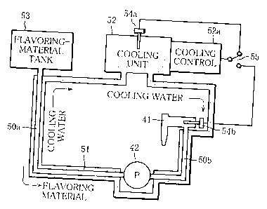
material application device. As seen from FIG. 2 showing
the schematic structure thereof, the flavoring-material
application device includes, as basic functional components,
an application nozzle 41 and a pump 42 for supplying the
flavoring material to the application nozzle 41. This
flavoring-material application device is characterized by
further including a cooling-water passage 51 which allows a
coolant to circulate along a flavoring-material passage 50
through which the flavoring material is supplied by the
pump 42, thereby cooling the flavoring material, and a
cooling unit 52 for controlling the temperature of the
coolant supplied to the cooling-water passage 51.
In the flavoring-material application device, the
primary side (source side) of the pump 42 is connected to a
flavoring-material tank 53 by a first feed pipe 50a, and
the secondary side (drain side) of the pump 42 is connected
to tiie appllC:c1L1CJI1 nozzle 41 by a secona feea pipe 50b.
The feed pipes 50a, 50b constitute the above-mentioned
flavoring-material supply passage 50. The cooling-water
passage 51 consists of pipes which surround the feed pipes
CA 02599317 2007-08-27
- 12 -
50a, 50b to form a double pipe structure, and auxiliary
pipes used to connect those pipes and the cooling unit 52
in series. The cooling-water passage 51 allows the cooling
water (coolant) discharged from the cooling unit 52 to
circulate along the flavoring-material supply passage 50,
thereby cooling the flavoring material. Specifically, the
cooling-water passage 51 provides a circulation path along
which the cooling water sent out from the cooling unit 52
is supplied to the application-nozzle-41 side, flows toward
the pump 42, in the direction opposite to the direction of
supply of the flavoring material, and returns from the
flavoring-material-tank-53 side to the cooling unit 52.
The cooling unit 25 includes a cooler which, under the
control by a cooling control section 52a, draws heat from
the cooling water to drop the temperature thereof, on the
basis of the temperature detected by first and second
temperature sensors 54a, 54b. Specifically, the first
temperature sensor 54a is provided to detect the
temperature of the cooling water in the cooling unit 52,
while the second temperature sensor 54b is provided to
detect the temperature of the flavoring material in the
application nozzle 41. The temperature information
obtained by the temperature sensors 54a, 54b is selectively
provided to the cooling control section 53 depending on the
operating state of the wrapping machine 20.
Specifically, the cooling control section 52a includes
a first control system for controlling the temperature of
the cooling water sent out from the cooling control unit 52
on the basis of the temperature of the cooling water
detected by the first temperature sensor 54a, and a second
control system for controlling the temperature of the
cooling water sent out from the cooling control unit 52 on
the basis of the temperature of the flavoring material
CA 02599317 2007-08-27
- 13 -
supplied to the application nozzle 41, detected by the
second temperature sensor 54b. By selectively activating
the first and second control systems, the cooling control
section 52a controls the temperature of the cooling water
depending on the operating state of the cigarette making
apparatus 20.
FIG. 3 schematically shows the control process
performed in the cooling control system constructed as
described above. When the cigarette making apparatus is
powered on, the cooling control unit 52 is activated so
that the control starts (Step S1). First, the cooling
control section controls the temperature of the cooling
water sent out from the cooling control unit 52 on the
basis of the temperature of the cooling water detected by
the first temperature sensor 54a (Step S2). Under such
control on the operation of the cooling unit 52, by means
of the cooling water circulating through the cooling-water
passage 51, the flavoring material supplied through the
flavoring-material supply passage 50 is kept approximately
at the temperature of the cooling water, in spite of
variations in machine temperature around.
After this preparation, the cigarette making apparatus
starts operation, and when an instruction to start the
application of the flavoring material is given, a needle
(not shown) of the application nozzle 41 is brought into an
open position, and at the same time, the pump 42 is
activated (Steps S3, S4). By the pump 42 activated, the
flavoring material is supplied from the flavoring-material
tank 51 to the application nozzle 41, so that the
application nozzle 41 starts to appiy the fiavoring
material to the wrapping-paper web W. When the cigarette
making machine transfers to the flavoring-material
application operation, the cooling control section
CA 02599317 2007-08-27
- 14 -
activates the second control system in place of the first
control system, to control the temperature of the cooling
water sent out from the cooling control unit 52 on the
basis of the temperature of the flavoring material in the
application nozzle 41, detected by the second temperature
sensor 54b (Step S5). Specifically, since the temperature
of the flavoring material in the application nozzle 41 is
determined primarily by the temperature of the cooling
water near the application nozzle 41, the temperature of
the cooling water sent out from the cooling unit 52 is
controlled so that the cooling water near the application
nozzle 41 is at a predetermined temperature.
This cooling-water temperature control by the second
control system continues until the flavoring-material
application operation is stopped (Step S6). When the
flavoring-material application operation is stopped, the
needle of the application nozzle 41 is brought into a
closed position, and at the same time, the pump 42 is
deactivated (Step S7). Then, the cooling control section
returns to the cooling-water temperature control by the
first control system at Step S2. It is to be noted that
the stop of the flavoring-material application operation
mentioned above means a temporary rest of the cigarette
making apparatus, for example in brake time of a factory.
In the cigarette making apparatus arranged, as
described above, to cool the flavoring material supplied to
the application nozzle 41 by means of the cooling water
circulating through the cooling-water passage provided
along the flavoring-material supply passage 50, even when
JV the machine telClperatLAre rises wi11l-~~' LI1e apparatus 16
operating, the flavoring material can be kept at a fixed
temperature in spite of the rise in machine temperature.
Thus, variation in viscosity of the flavoring material due
CA 02599317 2007-08-27
- 15 -
to variation in temperature is prevented, and therefore,
the flavoring material applied from the application nozzle
41 to the wrapping-paper web W can be stably controlled to
a fixed amount per unit area, only by controlling the rate
of supply of the flavoring material to the application
nozzle 41 by controlling the rotating speed of the pump 42.
Further, while the flavoring-material application
operation is suspended, by detecting the temperature of the
cooling water and controlling it to be a predetermined
temperature, the entire flavoring-material application
device can almost be kept at a low temperature without
being affected by the machine temperature around.
Meanwhile, during the flavoring-material application
operation, it is sufficient to control the flavoring
material to keep a fixed temperature, by controlling the
temperature of the cooling water accurately, on the basis
of the temperature of the flavoring material in the
application nozzle 41. Thus, the control system does not
need to have an excessively complex configuration. Since
the flavoring material can be kept at a fixed viscosity by
controlling the temperature of the flavoring material in a
simple and effective manner, the amount per unit area of
the flavoring material applied to the wrapping-paper web W
can be fixed in spite of variations in machine temperature
around. Thus, the quality of the cigarettes manufactured
can be easily stabilized.
In order to confirm the positive effect of the
flavoring-material application device having the above-
described cooling water passage 51, how the temperature of
the fiavorilig material aiid tiie rate oi di5ciiarye of the
flavoring material from the application nozzle 41 vary with
time, during the operation of the cigarette making
apparatus was investigated. The results obtained are shown
CA 02599317 2007-08-27
- 16 -
in FIGS. 4 to 6. FIG. 4 shows characteristics when the
cooling water passage 51 was not utilized. FIG. 5 shows
characteristics when the cooling water was kept at a fixed
temperature (25 C) by utilizing the cooling water passage
51. FIG. 6 shows characteristics when the temperature of
the cooling water was controlled on the basis of the
temperature of the flavoring material in the application
nozzle 42, so as to keep the flavoring material at 25 C.
In FIGS. 4 to 6, average variation in rate of discharge of
the flavoring material is shown in solid line, while
average variation in temperature of the flavoring material
in the application nozzle 41 is shown in dashed line.
As clear from the comparison between FIG. 4, 5, and 6
showing the variation in temperature of the flavoring
material and the variation in rate of discharge of the
flavoring material, in the conventional, common flavoring-
material application device without the cooling water
passage 51, the temperature of the flavoring material is
affected by the machine temperature around and begins to
rise about an hour after the machine starts operating, so
that the amount per unit area of the flavoring material
applied increases over a determined value. Meanwhile, in
the flavoring-material application device provided with the
cooling water passage 51, the rise in temperature of the
flavoring material can be suppressed effectively even when
the machine temperature around rises. However, when only
the cooling water is controlled to a fixed temperature, a
temporary increase in rate of discharge of the flavoring
material can happen when the machine operation is resumed
0 () F y y L ' r FIG. R_ _ ~
JV after a reJl., as 511o1^111 in FVJ. 1"1Cal1w1111e, it was
confirmed that in the arrangement where the temperature of
the cooling water passage is controlled on the basis of the
temperature of the flavoring material in the application
CA 02599317 2007-08-27
- 17 -
nozzle 41, the rate of discharge of the flavoring material
can be kept within a determined allowable range even when
the machine operation is resumed after a rest, as shown in
FIG. 6.
The temporary increase in rate of discharge of the
flavoring material at the time of resuming the operation,
observed in the case where the temperature of the cooling
water is detected and controlled to be fixed, is thought to
be due to the following reason: During the rest, the
temperature of the cooling water sent out from the cooling
unit 52 can be fixed. However, the temperature of the
cooling water flowing in the cooling water passage 51 is
affected by the machine temperature around, and gradually
rises, so that, near the application nozzle 41 and near the
pump 42, the cooling-water temperature exceeds the control
target temperature. Thus, the flavoring material which
fills the supply passage 52 and stays still while the
flavoring-material application operation is suspended rises
in temperature, although not to a great degree.
Consequently, when the machine operation is resumed after
the rest, the flavoring material temporarily decreased in
viscosity is supplied to the application nozzle 41, which
results in an increase in rate of discharge of the
flavoring material. In contrast, when, as described above,
the temperature of the flavoring material in the
application nozzle 41 is detected and the temperature of
the cooling water is controlled on the basis of the
detected temperature of the flavoring material, the
temperature of the flavoring material discharged from the
application nozzle 41 to the wrapping-paper web W can be
fixed. Thus, the rate of discharge of the flavoring
material from the application nozzle 41 can be easily
controlled to be fixed. For this reason, it is very useful
CA 02599317 2007-08-27
- 18 -
to control the temperature of the flavoring material by
switch between the two control systems as described above.
The present invention is not limited to the above-
described embodiment. For example, although in the example
described, the flavoring material is applied to the
wrapping-paper web P in the pattern of a longitudinal line,
the present invention is applicable to the case where the
flavoring material is applied to the wrapping-paper web in
the pattern of two or more longitudinal lines with a
determined space between. Further, although the example in
which single wrapper cigarettes, namely cigarettes with one
wrapper W enclosing shredded tobacco K, are manufactured
has been taken, the present invention is applicable to the
manufacture of double wrapper cigarettes, namely cigarettes
with two wrappers W enclosing shredded tobacco K, likewise.
In the case of the double wrapper cigarettes, it can be
arranged such that the flavoring material is applied
between the two layered wrappers W, namely on the inside,
or joint surface of one of the two layered wrappers W.
Further, in place of the cooling water, a variety of
coolants can be used to cool the flavoring material, and
the cooling unit 52 is not limited to a particular
structure. In other respects, the present invention can be
modified in various ways, without deviating from its scope.