Note: Descriptions are shown in the official language in which they were submitted.
CA 02599450 2010-02-24
CARTONS WITH DISPENSER SECTIONS
BACKGROUND
[0001] Enclosed cartons with dispensing features have been used in the past.
Many
such cartons allow for the creation of dispenser openings by providing
dispenser
portions demarcated by tear lines. The dispenser portions can be wholly or
partially
separated from the carton to create an opening from which articles can be
removed
from the carton. Many conventional dispenser openings, however, provide
insufficient access to containers accommodated within the carton. Other
dispenser
openings may provide sufficient access to containers within a carton, but the
sections
of the carton removed during opening of the dispenser portion compromise the
structural integrity of the carton.
SUMMARY
[0002] According to one embodiment of the present invention, a carton
comprises a
bottom panel, a top panel, first and second side panels, and first and second
end
panels. A dispenser section is formed in the carton such that when the
dispenser
section is opened, a dispenser opening is formed at least in an upper portion
of one
side panel, the top panel, and an upper portion of a second side panel.
Articles stored
in the carton can be dispensed from the dispenser opening.
[0003] According to one aspect of the embodiment, when the dispenser section
is
opened, the opening provides easy access to containers or other articles
accommodated within the carton. The end panels of the carton can remain intact
after
opening of the dispensing feature to allow easy carrying of the opened carton
by
handle apertures disposed in the end panels. Portions or substantially all of
the upper
portions of the side panels can be removed during opening to provide access to
the
articles from either one or both sides of the carton.
[0004] According to another embodiment of the present invention, a dispenser
section is formed in a carton such that when the dispenser section is opened,
a
dispenser opening is formed in at least a portion of a first side panel, a top
panel, a
second side panel, and an end panel.
1
CA 02599450 2011-05-24
[0005] According to one aspect of the embodiment, the portion of the top panel
of
the carton removed during opening can be selected to provide access to a
desired
number of articles in the opened carton. The dispenser opening can extend down
into
the side panels to allow access from the sides of the carton, and can also
extend into
the end panel to allow access from the opened carton end. The sides and end of
the
opened carton can be sufficiently high to retain a high degree of structural
rigidity for
the carton. Handles can be formed in the carton ends that allow the carton to
be
carried after opening of the carton.
[0006] According to one aspect of the present invention there is provided a
carton
and a plurality of articles contained therein, the carton comprising a bottom
panel; a
first side panel comprising a first lower side panel and a first upper side
panel, the
first upper side panel being foldably connected to the first lower side panel
at a first
fold line extending across the first side panel; a second side panel
comprising a
second lower side panel and a second upper side panel, the second upper side
panel
being foldably connected to the second lower side panel at a second fold line
extending across the second side panel; a top panel; a plurality of first end
flaps at a
first end of the carton and forming a first end panel, the first end flaps
comprising a
first side end flap foldably connected to the first side panel, a second side
end flap
foldably connected to the second side panel, a top end flap foldably connected
to the
top panel, and a bottom end flap foldably connected to the bottom panel; a
plurality
of second end flaps at a second end of the carton and forming a second end
panel, the
second end flaps comprising a first side end flap foldably connected to the
first side
panel, a second side end flap foldably connected to the second side panel, a
top end
flap foldably connected to the top panel, and a bottom end flap foldably
connected to
the bottom panel; a first handle formed in the first end panel comprising a
handle
opening in at least one of the first and second side end flaps at the first
end and a
handle opening in at least one of the top and bottom end flaps at the first
end; and a
second handle formed in the second end panel comprising a handle opening in at
least
one of the first and second side end flaps at the second end and a handle
opening in at
least one of the top and bottom end flaps at the second end, wherein a
dispenser
pattern defines a dispenser section at least in the first upper side panel and
the second
upper side panel, wherein the dispenser section comprises substantially all of
the top
panel, wherein the dispenser pattern comprises a first transverse tear line
extending
along and collinear with the first fold line and a second transverse tear line
extending
along and collinear with the second fold line, each of the first and second
transverse
2
CA 02599450 2011-05-24
tear lines at least partially defining an edge of the dispenser section, and
each of the
first and second transverse tear lines extending across the respective first
and second
side panels from the first end panel to the second end panel; wherein the
dispenser
pattern further comprises a first longitudinal tear line and a second
longitudinal tear
line, the first and second longitudinal tear lines extending from a respective
end of the
first transverse tear line to a respective end of the second transverse tear
line, wherein
the first upper side end flap, the top end flap, and the second upper side end
flap of
the plurality of first end flaps are foldably connected to the respective
first upper side
panel, top panel, and second upper side panel along the first longitudinal
tear line, and
wherein the first upper side end flap, the top end flap, and the second upper
side end
flap of the plurality of second end flaps are foldably connected to the
respective first
upper side panel, top panel, and second upper side panel along the second
longitudinal tear line.
[0006.1] According to a further aspect of the present invention there is
provided a
method of opening a carton in accordance with the above aspect comprising:
pulling
the dispenser section so that substantially all of the first upper side panel
is at least
partially torn away from a remainder of the carton; pulling the dispenser
section so
that substantially all of the top panel is at least partially torn away from
the remainder
of the carton; and pulling the dispenser section so that a portion of the
second side
panel is at least partially torn away from the remainder of the carton.
[0006.2] According to another aspect of the present invention there is
provided a blank
for forming a carton, the blank comprising a bottom panel; a first side panel
comprising a first lower side panel and a first upper side panel foldably
connected to
the first side panel, the first upper side panel being foldably connected to
the first
lower side panel at a first fold line extending across the first side panel; a
second side
panel comprising a second lower side panel and a second upper side panel
foldably
connected to the second side panel, the second upper side panel being foldably
connected to the second lower side panel at a second fold line extending
across the
second side panel; a top panel; a plurality of first end flaps extending along
a first
marginal area of the blank for closing a first end of the carton, the first
end flaps
comprising a first side end flap foldably connected to the first side panel, a
second
side end flap foldably connected to the second side panel, a top end flap
foldably
connected to the top panel, and a bottom end flap foldably connected to the
bottom
panel; a plurality of second end flaps extending along a second marginal area
of the
2a
CA 02599450 2011-05-24
blank for closing a second end of the carton, the second end flaps comprising
a first
side end flap foldably connected to the first side panel, a second side end
flap
foldably connected to the second side panel, a top end flap foldably connected
to the
top panel, and a bottom end flap foldably connected to the bottom panel;
features for
forming a first handle at the first end of the carton, the features comprising
a handle
opening in at least one of the first and second side end flaps at the first
end and a
handle opening in at least one of the top and bottom end flaps at the first
end; and
features for forming a second handle at the second end of the carton, the
features
comprising a handle opening in at least one of the first and second side end
flaps at
the second end and a handle opening in at least one of the top and bottom end
flaps at
the second end, wherein a dispenser pattern defines a dispenser section at
least in the
first upper side panel and the second upper side panel, wherein the dispenser
section
comprises substantially all of the top panel, wherein the dispenser pattern
comprises a
first transverse tear line extending along and collinear with the first fold
line and a
second transverse tear line extending along and collinear with the second fold
line,
each of the first and second transverse tear lines at least partially defining
an edge of
the dispenser section, and each of the first and second transverse tear lines
extending
across the respective first and second side panels from the first marginal
area of the
blank to the second marginal area of the blank; wherein the dispenser pattern
further
comprises a first longitudinal tear line and a second longitudinal tear line,
the first and
second longitudinal tear lines extending from a respective end of the first
transverse
tear line to a respective end of the second transverse tear line, wherein the
first upper
side end flap, the top end flap, and the second upper side end flap of the
plurality of
first end flaps are foldably connected to the respective first upper side
panel, top
panel, and second upper side panel along the first longitudinal tear line, and
wherein
the first upper side end flap, the top end flap, and the second upper side end
flap of
the plurality of second end flaps are foldably connected to the respective
first upper
side panel, top panel, and second upper side panel along the second
longitudinal tear
line.
[0007] Other aspects, features, and details of the present invention can be
more
completely understood by reference to the following detailed description of
exemplary embodiments taken in conjunction with the drawings and from the
appended claims.
2b
CA 02599450 2011-05-24
[0008] According to common practice, the various features of the drawings
discussed below are not necessarily drawn to scale. Dimensions of various
features
and elements in the drawings may be expanded or reduced to more clearly
illustrate
the embodiments of the invention.
2c
CA 02599450 2007-08-27
WO 2006/099426 PCT/US2006/009140
BRIEF DESCRIPTION OF THE DRAWINGS
[0009] FIG. 1 is a plan view of a blank from which a carton having a
dispenser section according to a first embodiment of the invention is formed.
[0010] FIG. 2 is a plan view of a folded and glued blank from which the first
carton embodiment is formed.
[0011] FIG. 3 is an end view of the first carton embodiment partially erected
and filled with containers.
[0012] FIG. 4 is a perspective view showing one side of the first carton
embodiment.
[0013] FIG. 5 illustrates the opposite side of the first carton embodiment.
[0014] FIG. 6 illustrates the side of the carton opposite to that shown in
FIG.5.
[0015] FIG. 7 illustrates opening of the first carton embodiment.
[0016] FIG. 8 is a perspective view of the opened first carton embodiment.
[0017] FIG. 9 is a plan view of a blank from which a carton having a
dispenser section according to a second embodiment of the invention is formed.
[0018] FIG. 10 is a perspective view showing one side of the second carton
embodiment.
[0019] FIG. 11 illustrates the opposite side of the second carton embodiment.
[0020] FIG. 12 illustrates one side of the second carton embodiment after
opening of the carton.
[0021] FIG. 13 illustrates the opposite side of the opened second carton
embodiment.
[0022] FIG. 14 is a plan view of a blank from which a carton having a
dispenser section according to a third embodiment of the invention is formed.
[0023] FIG. 15 illustrates one side of the third carton embodiment.
-3-
CA 02599450 2007-08-27
WO 2006/099426 PCT/US2006/009140
[0024] FIG. 16 illustrates the opposite side of the third carton embodiment.
[0025] FIG. 17 illustrates use of a handle carrying feature of the third
carton
embodiment.
[0026] FIG. 18 illustrates the third carton embodiment after opening of the
carton.
[0027] FIG. 19 is a plan view of a blank from which a carton having a
dispenser section according to a fourth embodiment of the invention is formed.
[0028] FIG. 20 illustrates one side of the fourth carton embodiment.
[0029] FIG. 21 illustrates the fourth carton embodiment after opening.
[0030] FIG. 22 is a plan view of a blank from which a carton having a
dispenser section according to a fifth embodiment of the invention is formed.
[0031] FIG. 23 is a perspective view of the fifth carton embodiment.
[0032] FIG. 24 illustrates one side of the fifth carton embodiment.
[0033] FIG. 25 illustrates opening of the fifth carton embodiment.
[0034] FIG. 26 is an end view of the fifth carton embodiment after opening
and with the dispenser section hingedly attached.
[0035] FIG. 27 is a perspective view of the fifth carton embodiment after
opening.
[0036] FIG. 28 is a plan view of a blank from which a carton having a
dispenser section according to a sixth embodiment of the invention is formed.
[0037] FIG. 29 is a perspective view showing one side of the sixth carton
embodiment.
[0038] FIG. 30 is a perspective view of the sixth carton embodiment after
opening.
-4-
CA 02599450 2007-08-27
WO 2006/099426 PCT/US2006/009140
DETAILED DESCRIPTION
[0039] The present invention generally relates to opening and dispensing
features for cartons that contain articles such as containers, bottles, cans,
etc. The
articles can be used for packaging food and beverage products, for example.
The
articles can be made from materials suitable in composition for packaging the
particular food or beverage item, and the materials include, but are not
limited to,
aluminum and/or other metals; glass; plastics such as PET, LDPE, LLDPE,
HDPE, PP, PS, PVC, EVOH, and Nylon; and the like, or any combination thereof.
[0040] Cartons according to the present invention can accommodate articles
of any shape. For the purpose of illustration and not for the purpose of
limiting
the scope of the invention, the following detailed description describes
beverage
containers (e.g., glass beverage bottles) as disposed within the carton
embodiments. In this specification, the terms "lower," "bottom," "upper" and
"top" indicate orientations determined in relation to fully erected and
upright
cartons.
[0041] According to a first embodiment of the invention, illustrated by FIGS.
1-8, a dispenser opening is created in a carton 90 (illustrated in FIG. 4) by
removing or at least partially separating an upper portion of a first side
panel 20, a
top panel 30, and an upper portion of a second side panel 40 of the carton 90.
End
panels 92, 94 of the carton 90 may remain intact to allow easy carrying of the
opened carton by handles disposed in the end panels. When opened, the carton
90
provides easy access to articles from the top and from either side of the
carton.
[0042] FIG. 1 is a plan view of a blank 8 used to form the carton 90
(illustrated in FIG. 4) according to the first embodiment of the invention.
The
blank 8 can be symmetric or partially symmetric about a longitudinal
centerline
CL and about a transverse centerline CT. Therefore, certain elements in the
drawing figures have similar or identical reference numerals in order to
reflect the
whole or partial longitudinal and/or transverse symmetries. As shown in FIG.
1,
the blank 8 comprises a glue flap 14 foldably connected to a rectangular
bottom
-5-
CA 02599450 2007-08-27
WO 2006/099426 PCT/US2006/009140
panel 10 at a first transverse fold line 16. The bottom panel 10 is foldably
connected to the first side panel 20 at a second transverse fold line 21, the
top
panel 30 is foldably connected to the first side panel 20 at a third
transverse fold
line 31, and the second side panel 40 is foldably connected to the top panel
30 at a
fourth transverse fold line 41. Oppositely disposed bottom end flaps 12 are
foldably connected to the bottom panel 10 at longitudinal fold lines 15.
Oppositely disposed top end flaps 32 are foldably connected to the top panel
30 at
longitudinal fold lines 74, 78. Circular handle apertures 34 can be included
in the
top end flaps 32.
[0043] The first side panel 20 comprises a first upper side panel 24 and a
first
lower side panel 22 foldably connected at a transverse fold line 72 which may
be
partially interrupted at a section 86. Oppositely disposed end flaps 28 are
foldably
connected to the first upper side panel 24 at the longitudinal fold lines 74,
78.
Similarly, oppositely disposed end flaps 26 are foldably connected to the
first
lower side panel 22 at oblique fold lines 54. The second side panel 40 can
comprise a second upper side panel 44 and a second lower side panel 42
foldably
connected at a transverse fold line 76. Oppositely disposed end flaps 48 are
foldably connected to the second upper side panel 44 at the longitudinal fold
lines
74, 78. Similarly, oppositely disposed end flaps 46 are foldably connected to
the
second lower side panel 42 at the oblique fold lines 54. The longitudinal fold
lines 15, 74, 78 and the oblique fold lines 54 may be straight fold lines, or
may be
offset at one or more locations to account for, for example, blank thickness.
[0044] The blank 8 includes four diamond corners 50. Two are formed in the
first upper side panel 24, the first lower side panel 22, and the end flaps
26, 28;
these two diamond corners 50 are located at opposite ends of the first side
panel
20. Similarly, two diamond corners 50 are formed in the second upper side
panel
44, the second lower side panel 42, and the end flaps 46, 48; these two
diamond
corners 50 are located at opposite ends of the second side panel 40. At each
of
-6-
CA 02599450 2007-08-27
WO 2006/099426 PCT/US2006/009140
these locations, the diamond corners 50 are defined in part by transverse fold
lines
58, 60, V-shaped fold lines 52, 56, and the oblique fold line 54.
[0045] According to one aspect of this embodiment, a dispenser pattern 70
formed in the blank 8 defines a dispenser section 71. The dispenser pattern 70
can
generally comprise a pattern of lines of disruption in the blank 8 that allow
the
dispenser section 71 to remain hingedly attached or to be completely removed
from the carton 90 (FIG. 4). The dispenser pattern 70 may comprise, for
example, tear lines that extend along the transverse fold lines 72, 76 and the
longitudinal fold lines 74, 78. The dispenser pattern 70 may also define an
opening section or flap 75 within the dispenser section 71. The opening flap
75 is
located in the first upper side panel 24 adjacent to the lower side panel 22.
The
opening flap 75 may be defined by a curved opening line 80, a V-shaped opening
line 82, an inverted T-shaped opening line 84, and the section 86 of the
transverse
fold line 72. The tear line in the transverse fold line 72 extends across the
length
of the first side panel 20 and the tear line in the transverse fold line 76
extends
across the length of the second side panel 40. A trapezoidal panel 88 can be
defined in the opening flap 75 adjacent to the section 86 of the transverse
fold line
72.
[0046] The lines that comprise the opening flap 75 can be lines of disruption
designed to provide easy access or entry into the opening flap 75. For
example,
the lines 84 can be tear lines designed to break upon pressing on the opening
flap
75. The lines 80, 82 and 86 can be lines designed to flex or deform upon
pressing
on the opening flap 75, which allows a user to obtain a firm grasp on the flap
75.
In the illustrated embodiment, the opening line 84 is a cut/space line, and
the lines
80, 82, 86 are cut/crease lines.
[0047] An exemplary method of erection of the carton 90 from the blank 8
will now be discussed with reference to FIGS. 2-5. FIG. 2 illustrates the
blank 8
in a partially erected state with the print side or exterior side of the blank
8 facing
out. The blank 8 is folded 1800 about the transverse fold line 72, and the
second
-7-
CA 02599450 2007-08-27
WO 2006/099426 PCT/US2006/009140
lower side panel 42 also is folded 1800 about the transverse fold line 76. The
second lower side panel 42 overlaps the glue flap 14 and is adjacent the
bottom
panel 10. Referring also to FIG. 1, the second lower side panel 42 is adhered
or
secured to the glue flap 14 by glue, adhesive, or other means known within the
art.
[0048] FIG. 3 illustrates the blank 8 of FIG. 2 opened into a partially
assembled carton loaded with containers C arranged in a 2x6 orientation.
Articles
such as, for example, the containers C may be loaded into the partially
assembled
carton in a conventional manner at any time before one or both ends of the
carton
are closed by the end flaps 12, 26, 28, 32, 46, 48.
[0049] FIG. 4 is a perspective view of one side of the erected carton 90. FIG.
is a front elevational view of the opposite side of the erected carton 90.
Referring also to FIG. 3, the ends of the carton 90 may be formed by folding
inwardly and gluing or otherwise adhering the end flaps 12, 26, 28, 32, 46, 48
to
form the first end panel 92 and the second end panel 94 at first and second
ends of
the carton 90, respectively. FIG. 4 illustrates the location of the dispenser
pattern
70 including the opening flap 75 on the first side panel 20 of the erected
carton
90. FIG. 5 illustrates the second side panel 40 and the tear lines of the
dispenser
pattern 70 that extend along the transverse fold line 76 and the fold lines
74, 78.
[0050] FIG. 6 illustrates the opening flap 75 of the dispenser section 71 in
detail. The curved opening line 80 defines an upper perimeter of the opening
flap
75, and can extend across a significant portion of the width of the carton 90.
The
transverse fold line 72 defines a lower edge of the opening flap 75. The V-
shaped
opening line 82, the inverted T-shaped opening line 84 and the section 86
define
the trapezoidal panel 88.
[0051] One exemplary method of opening of the carton 90 will now be
discussed with reference to FIGS. 6-8. Referring to FIG. 6, a user can breach
one
or more of lines 80, 82, 84, 72, optionally including the section 86 of the
transverse fold line 72, in the opening flap 75 with his fingers in order to
obtain a
grasp of the dispenser section 71. In the exemplary embodiment, the opening
flap
-8-
CA 02599450 2007-08-27
WO 2006/099426 PCT/US2006/009140
75 is primarily breached at the opening line 84, although other lines of the
opening flap 75 may be torn to varying degrees. If the section 86 of the
transverse
fold line 72 is torn completely when the opening flap 75 is breached, the
trapezoidal panel 88 will separate with the dispenser section 71. Otherwise,
the
trapezoidal panel 88 can remain attached to the first lower side panel 22.
[0052] Referring to FIG. 7, after the opening flap 75 has been breached, the
dispenser section 71 is pulled vertically away from the first lower side panel
22,
and the carton 90 tears open along the dispenser pattern 70. That is, the
first
upper side panel 24 is torn away from the first lower side panel 22 along the
transverse fold line 72, and the section 86 if applicable. Once the fold line
72 is
torn across the length of the carton 90, the first upper side panel 24 may be
pulled
vertically along the longitudinal fold lines 74, 78 to disengage the first
upper side
panel 24 from the first end panel 92 and the second end panel 94,
respectively.
Opening along the dispenser pattern 70 continues along the longitudinal fold
lines
74, 78 as the top panel 30 and then the second upper side panel 44 are torn
away
from the first and second end panels 92, 94. Once the transverse fold line 76
is
reached, the dispenser section 71 can be left to remain hingedly attached. to
the
carton 90 (not shown). Alternatively, the second upper side panel 44 of the
dispenser section 71 may be pulled horizontally, removing the dispenser
section
71 from the remainder of the carton 90 along the upper edge of the second
lower
side panel 42.
[0053] FIG. 8 illustrates the opened carton 90 with the dispenser section 71
completely removed from the remainder of the carton 90. The opened carton 90
allows access to and visibility of the containers C from both sides and from
the
top of the carton 90. The first and second end panels 92, 94 of the carton 90
remain to allow easy carrying of the opened carton 90 by the handles 34
disposed
in the end panels. The first carton embodiment can be, for example, stored
inside
a refrigerator, and provides easy access to, for example, glass or plastic
beverage
bottles. The exemplary 2x6 container configuration generally will allow the
-9-
CA 02599450 2007-08-27
WO 2006/099426 PCT/US2006/009140
carton 90 to be placed and stored in a door shelf of a refrigerator, if
desired.
Optionally, the carton 90 can be placed on another shelf in the refrigerator
or on
another surface, where the carton provides easy access to articles from either
side
and/or from the top of the carton.
[0054] According to a second embodiment of the invention, illustrated by
FIGS. 9-13, a dispenser opening is created in a carton 190 by removing or at
least
partially separating a section of a second side panel 140, a top panel 130,
and an
upper portion of a first side panel 120 of the carton 190. The section of the
second side panel 140 that remains with the carton 190 provides additional
stability to the carton. When opened, the carton 190 provides easy access to
articles from the top and the open side of the carton.
[0055] FIG. 9 is a plan view of a blank 108 used to form the carton 190
(illustrated in FIG. 10) according to the second embodiment of the invention.
The blank 108 can be symmetric or partially symmetric about a longitudinal
centerline CL and about a transverse centerline CT. Therefore, certain
elements in
the drawing figures have similar or identical reference numerals in order to
reflect
the whole or partial longitudinal and/or transverse symmetries. As shown in
FIG.
9, the blank 108 comprises a glue flap 114 foldably connected to a rectangular
bottom panel 110 at a first transverse fold line 116. The bottom panel 110 is
foldably connected to the first side panel 120 at a second transverse fold
line 121,
the top panel 130 is foldably connected to the first side panel 120 at a third
transverse fold line 131, and the second side panel 140 is foldably connected
to
the top panel 130 at a fourth transverse fold line 141. Oppositely disposed
bottom
end flaps 112 are foldably connected to the bottom panel 110 at longitudinal
fold
lines 115. Oppositely disposed top end flaps 132 are foldably connected to the
top
panel 130 at longitudinal fold lines 174, 178. Circular handle apertures 134
can
be included in the top end flaps 132.
-10-
CA 02599450 2007-08-27
WO 2006/099426 PCT/US2006/009140
[0056] The first side panel 120 can comprise a first upper side panel 124 and
a
first lower side panel 122 foldably connected at a transverse fold line 172.
Oppositely disposed end flaps 128 are foldably connected to the first upper
side
panel 124 at the longitudinal fold lines 174, 178. Similarly, oppositely
disposed
end flaps 126 are foldably connected to the first lower side panel 122 at
oblique
fold lines 154. The second side panel 140 can comprise a second upper side
panel
144 and a second lower side panel 142 foldably connected at a transverse fold
line
143. Oppositely disposed end flaps 148 are foldably connected to the second
upper side panel 144 at the oblique fold lines 154. Similarly, oppositely
disposed
end flaps 146 are foldably connected to the second lower side panel 142 at the
oblique fold lines 154. The longitudinal fold lines 115, 174, 178 and the
oblique
fold lines 154 may be straight fold lines, or may be offset at one or more
locations
to account for, for example, blank thickness.
[0057] The blank 108 includes four diamond corners 150. Two are formed in
the first upper side panel 124, the first lower side panel 122, and the end
flaps
126, 128; these two diamond corners 150 are located at opposite ends of the
first
side panel 120. Similarly, two diamond corners 150 are formed in the second
upper side panel 144, the second lower side panel 142, and the end flaps 146,
148;
these two diamond corners 150 are located at opposite ends of the second side
panel 140. At each of these locations, the diamond corners 150 are defined in
part
by transverse fold lines 158, 160, V-shaped fold lines 152, 156, and the
oblique
fold lines 154.
[0058] According to one aspect of the second embodiment, a dispenser pattern
170 formed in the blank 108 defines a dispenser section 171. The dispenser
pattern 170 can generally comprise a pattern of lines of disruption in the
blank
108 that allow the dispenser section 171 to remain hingedly attached to or to
be
completely removed from the carton (illustrated in FIG. 10). The dispenser
pattern 170 may comprise, for example, tear lines that extend along the
transverse
fold line 172 and the longitudinal fold lines 174, 178. The dispenser pattern
170
-11-
CA 02599450 2007-08-27
WO 2006/099426 PCT/US2006/009140
also defines an opening section or flap 175 within the dispenser section 171.
The
opening flap 175 is located near the top of the second upper side panel 144
adjacent to the top panel 130. The opening flap 175 may be defined by oblique
opening lines 180, a curved opening line 182, a V-shaped opening line 183, and
a
T-shaped opening line 184.
[0059] The lines that comprise the opening flap 175 can be lines of disruption
designed to provide easy access or entry into the opening flap 175. For
example,
the line 184 can be a tear line designed to break upon pressing on the opening
flap
175. The lines 182, 183 can be lines designed to flex or deform upon pressing
and
breaching the opening flap 175, which allows a user to obtain a firm grasp on
the
opening flap 175. The oblique opening lines 180 may be tear lines that allow
the
dispenser section 171 to initially tear along the second side panel 140.
[0060] The exemplary method discussed above for erecting the carton 90 of
the first embodiment from the blank 8 can be employed to erect the carton 190
of
the second embodiment. With reference to FIGS. 9-11, the method for erecting
the carton 190 from the blank 108 can be summarized as follows: With the print
or exterior side of the blank 108 facing out, the blank 108 is folded 180
about the
transverse fold line 172, and the second lower side panel 142 also is folded
180
about the transverse fold line 143. The second lower side panel 142 overlaps
the
glue flap 114 and is adjacent the bottom panel 110. The second lower side
panel
142 is adhered or otherwise secured to the glue flap 114 by glue, adhesive, or
other means known within the art.
[0061] FIG. 10 is a perspective view of one side of the erected carton 190,
and FIG. 11 is a perspective view of the opposite side of the carton 190. The
carton 190 is filled with containers C (not visible in FIGS. 10 and 11)
arranged in
a 2x6 orientation. The ends of the carton 190 may be closed by folding
inwardly
and gluing or otherwise adhering the end flaps 112, 126, 128, 132, 146, 148
(illustrated in FIG. 9) to form a first end panel 192 and a second end panel
194 at
each end of the carton 190. Articles may be loaded into the partially
assembled
-12-
CA 02599450 2007-08-27
WO 2006/099426 PCT/US2006/009140
carton in a conventional manner at any time before one or both ends of the
carton
190 are closed by the end flaps 112, 126, 128, 132, 146, 148.
[0062] Referring to FIG. 10, the tear lines of the pattern 170 extend along
the
transverse fold line 172, which is located in the first side panel 120. FIG.
11 is a
view of the opposite side of carton 190, and illustrates the location of the
opening
flap 175 near the top of the second upper side panel 144. The bottom edge of
the
opening flap 175 is defined by the oblique opening lines 180 and the T-shaped
line 184.
[0063] An exemplary method of opening of the carton 190 will now be
discussed with reference to FIGS. 10-12. Referring to FIGS. 10 and 11, a user
can breach one or more of the lines 182, 183, 184 in the opening flap 175 with
his
fingers in order to grasp the dispenser section 171. After the opening flap
175 has
been breached, the dispenser section 171 is torn vertically away from the
second
upper side panel 144 along the oblique opening tear lines 180. Opening along
the
dispenser pattern 170 continues along the tear lines in the longitudinal fold
lines
174, 178 as the top panel 130 and the first upper side panel 124 are separated
from
the first and second end panels 192, 194. Once the transverse fold line 172 is
reached, the dispenser section 171 can remain hingedly attached to the carton
190
(not illustrated). Alternatively, the first upper side panel 124 of the
disperser
section 171 may be pulled horizontally, removing the dispenser section 171
from
the first lower side panel 122 and the carton 190, as shown in FIG. 12.
[0064] FIGS. 12-13 illustrate the opened carton 190 with the dispenser
section 171 removed. From the open or dispensing side of the carton 190 shown
in FIG. 12, the containers C are readily accessible above the first lower side
panel
122. FIG. 13 illustrates the opposite side of the carton 190, where the second
upper side panel 144 remains intact up to the lower edge of the removed
opening
flap 175.
-13-
CA 02599450 2007-08-27
WO 2006/099426 PCT/US2006/009140
[0065] After the dispenser section 171 is removed, the carton 190 allows both
visibility of the containers C and easy access to the containers C, from the
open
side and from the top of the carton 190. The section of the second side panel
140
that remains with the carton 190 provides additional stability to the carton
190.
The end panels 192, 194 of the carton 190 may remain to allow easy carrying of
the opened carton 190 by the handles 134. The carton 190 can be stored inside
a
refrigerator, for example, and provides easy access to, for example, glass or
plastic
beverage bottles. According to one aspect of the present embodiment, the 2x6
configuration generally will allow the carton 190 to be stored in a door shelf
of a
refrigerator, if desired.
[0066] According to a third embodiment of the invention, illustrated by FIGS.
14-18, a dispenser opening is created in a carton 290 by removing or at least
partially separating an upper portion of a first side panel 220, a top panel
230, and
an upper portion of a second side panel 240 of the carton 290. When opened,
the
carton 290 provides easy access to articles from the top and from either side
of the
carton.
[0067] FIG. 14 is a plan view of a blank 208 used to form the carton 290
(illustrated in FIG. 15) according to the third embodiment of the invention.
As
shown in FIG. 14, the blank 208 comprises a glue flap 214 which is foldably
connected to a rectangular bottom panel 210 at a first transverse fold line
216.
The bottom panel 210 is foldably connected to the first side panel 220 at a
second
transverse fold line 221, the top panel 230 is foldably connected to the first
side
panel 220 at a third transverse fold line 231, and the second side panel 240
is
foldably connected to the top panel 230 at a fourth transverse fold line 241.
Oppositely disposed bottom end flaps 212 are foldably connected to the bottom
panel 210 at longitudinal fold lines 215. Oppositely disposed top end flaps
232
are foldably connected to the top panel 230 at longitudinal fold lines 274,
278.
Handle apertures 234 can be included in the top end flaps 232. The top panel
230
-14-
CA 02599450 2007-08-27
WO 2006/099426 PCT/US2006/009140
also can comprise a first side top panel 236 and a second side top panel 238
foldably connected at a transverse fold line 237.
[0068] The first side panel 220 can comprise a first upper side panel 224 and
a
first lower side panel 222 foldably connected at a transverse fold line 272
which
has a section 286. Oppositely disposed end flaps 228 are foldably connected to
the first upper side panel 224 at the longitudinal fold lines 274, 278.
Similarly,
oppositely disposed end flaps 226 are foldably connected to the first lower
side
panel 222 at oblique fold lines 254. The second side panel 240 can comprise a
second upper side panel 244 and a second lower side panel 242 foldably
connected at a transverse fold line 276. Oppositely disposed end flaps 248 are
foldably connected to the second upper side panel 244 at the longitudinal fold
lines 274, 278. Similarly, oppositely disposed end flaps 246 are foldably
connected to the second lower side panel 242 at the oblique fold lines 254.
The
longitudinal fold lines 215, 274, 278 and the oblique fold lines 254 may be
straight fold lines, or may be offset at one or more locations to account for,
for
example, blank thickness.
[0069] The blank 208 includes four diamond corners 250. Two are formed in
the first upper side panel 224, the first lower side panel 222, and the end
flaps
226, 228; these two diamond corners 250 are located at opposite ends of the
first
side panel 220. Similarly, two diamond corners 250 are formed in the second
upper side panel 244, the second lower side panel 242, and the end flaps 246,
248;
these two diamond corners 250 are located at opposite ends of the second side
panel 240. At each of these locations, the diamond corners 250 are defined in
part
by transverse fold lines 258, 260, V-shaped fold lines 252, 256, and the
oblique
fold line 254.
[0070] According to one aspect of the present embodiment, a dispenser
pattern 270 formed in the blank 208 defines a dispenser section 271. The
dispenser pattern 270 can generally comprise a pattern of lines of disruption
in the
blank 208 that allow the dispenser section 271 to remain hingedly attached or
to
-15-
CA 02599450 2007-08-27
WO 2006/099426 PCT/US2006/009140
be completely removed from the carton 290 (illustrated in FIG. 15). The
dispenser pattern 270 may comprise, for example, tear lines that extend along
the
transverse fold lines 272, 276 and the longitudinal fold lines 274, 278. The
dispenser pattern 270 also defines an opening section or flap 275 within the
dispenser section 271. The opening flap 275 is located in the first upper side
panel 224 adjacent to the lower side panel 222, and can be generally similar
in
shape, construction and function to the opening flap 75 illustrated in FIG. 1.
The
opening flap 275 may be defined by a curved opening line 280, a V-shaped
opening line 282, an inverted T-shaped opening line 284, and the section 286
of
the transverse fold line 272. The tear line in the transverse fold line 272
extends
across the length of the first side panel 220, and the tear line in the
transverse fold
line 276 extends across the length of the second side panel 240. A trapezoidal
panel 288 can be defined in the opening flap 275 adjacent to the section 286
of the
transverse fold line 272.
[0071] The exemplary methods for erecting cartons discussed above can also
be employed to erect the carton 290. FIGS. 15 and 16 illustrate opposite sides
of
the fully erected carton 290. In this embodiment, the containers C (not
visible in
FIGS. 15 and 16) are arranged in a 3x4 orientation, although other
configurations
can be used. Referring to FIG. 15, the transverse fold line 276 extends
through
the second side panel 240 and the longitudinal fold lines 274, 278 are
adjacent to
end panels 292, 294, respectively. Referring to FIG. 16, the opening flap 275
extends across a significant portion of the length of the first side panel 220
to
allow for easy opening of the dispenser section 271. One of the handle
apertures
234 is located in the second end panel 294; the corresponding handle aperture
234
(not visible in FIGS. 15-16) is located in the first end panel 292. FIG. 17
illustrates use of the handle apertures 234 to carry the carton 290.
-16-
CA 02599450 2007-08-27
WO 2006/099426 PCT/US2006/009140
[0072] Referring to FIGS. 16 and 18, a user typically opens the dispenser
section 271 along the dispenser pattern 270. The user initiates opening of the
dispenser section 271 by breaching the opening flap 275 and pulling the
dispenser
section 271 away from the remainder of the carton 290. The dispenser section
271 can remain hingedly attached to the carton 290 or be completely removed
from the carton 290 as shown in FIG. 18.
[0073] FIG. 18 illustrates the opened carton 290 with the dispenser section
271 removed. The opened carton 290 allows access to and visibility of the
containers C from both sides and from the top of the carton 290. The end
panels
292, 294 remain to allow for easy carrying of the opened carton 290 by the
handles 234 disposed in the end panels. The carton 290 can be stored inside a
refrigerator, and provides easy access to, for example, glass or plastic
beverage
bottles.
[0074] According to a fourth embodiment of the invention, illustrated by
FIGS. 19-21, a dispenser opening is created in a carton 390 by removing or at
least partially separating a section of a second side panel 340, a top panel
330, and
an upper portion of a first side panel 320 of the carton 390. The section of
the
second side panel 340 that remains with the carton 390 provides additional
stability to the carton. When opened, the carton 390 provides easy access to
articles from top and the open side of the carton.
[0075] FIG. 19 is a plan view of a blank 308 used to form the carton 390
(FIG. 20) according to the fourth embodiment of the invention. As shown in
FIG. 19, the blank 308 comprises a glue flap 314 foldably connected to a
rectangular bottom panel 310 at a first transverse fold line 316. The bottom
panel
310 is foldably connected to the first side panel 320 at a second transverse
fold
line 321, the top panel 330 is foldably connected to the first side panel 320
at a
third transverse fold line 331, and the second side panel 340 is foldably
connected
to the top panel 330 at a fourth transverse fold line 341. Oppositely disposed
bottom end flaps 312 are foldably connected to the bottom panel 310 at
-17-
CA 02599450 2007-08-27
WO 2006/099426 PCT/US2006/009140
longitudinal fold lines 315. Oppositely disposed top end flaps 332 are
foldably
connected to the top panel 330 at longitudinal fold lines 374, 378. Handle
apertures 334 can be included in the top end flaps 332. The top panel 330 also
can comprise a first side top panel 336 and a second side top panel 338
foldably
connected at a transverse fold line 337.
[0076] The first side panel 320 can comprise a first upper side panel 324 and
a
first lower side panel 322 foldably connected at a transverse fold line 372.
Oppositely disposed end flaps 328 are foldably connected to the first upper
side
panel 324 at the longitudinal fold lines 374, 378. Similarly, oppositely
disposed
end flaps 326 are foldably connected to the first lower side panel 322 at
oblique
fold lines 354. The second side panel 340 can comprise a second upper side
panel
344 and a second lower side panel 342 foldably connected at a transverse fold
line
343. Oppositely disposed end flaps 348 are foldably connected to the second
upper side panel 344 at the oblique fold lines 354. Similarly, oppositely
disposed
end flaps 346 are foldably connected to the second lower side panel 342 at the
oblique fold lines 354. The longitudinal fold lines 315, 374, 378 and the
oblique
fold lines 354 may be straight fold lines, or may be offset at one or more
locations
to account for, for example, blank thickness.
[0077] The blank 308 includes four diamond corners 350. Two are formed in
the first upper side panel 324, the first lower side panel 322, and the end
flaps
326, 328; these two diamond corners 350 are located at opposite ends of the
first
side panel 320. Similarly, two diamond corners 350 are formed in the second
upper side panel 344, the second lower side panel 342, and the end flaps 346,
348;
these two diamond corners 350 are located at opposite ends of the second side
panel 340. At each of these locations, the diamond corners 350 are defined in
part
by transverse fold lines 358, 360, V-shaped fold lines 352, 356, and the
oblique
fold line 354.
-18-
CA 02599450 2007-08-27
WO 2006/099426 PCT/US2006/009140
[0078] According to one aspect of the present embodiment, a dispenser
pattern 370 formed in the blank 308 defines a dispenser section 371. The
dispenser pattern 370 can be generally similar in shape, construction and
function
to the dispenser pattern 170 illustrated in FIG. 9, and generally comprises a
pattern of lines of disruption in the blank 308 that allow the dispenser
section 371
to remain hingedly attached to or to be completely removed from the carton 390
(illustrated in FIG. 20). An opening section or flap 375 in the section 371 is
defined by oblique opening lines 380, a curved opening line 382, a V-shaped
opening line 383, and a T-shaped opening line 384.
[0079] The exemplary methods discussed above for erecting cartons can also
be employed to erect the carton 390. FIG. 20 illustrates the fully erected
carton
390 filled with containers C (not visible) in a 3x4 orientation. The erected
carton
390 has a first end panel 392 and a second end panel 394 formed from the end
flaps illustrated in FIG. 19. The opening flap 375 is located at the top of
the
second upper side panel 344, and extends across a substantial portion of the
width
of the side panel 340 to allow for easy opening of the dispenser section 371.
A
user can breach one or more of the lines 382, 383, 384 of the opening flap 375
in
order to grasp the dispenser section 371. The dispenser section 371 may then
be
torn along the dispenser pattern 370 and removed from the carton 390.
[0080] FIG. 21 illustrates the opened carton 390. The carton 390 is open on
one side above the first lower side panel 322. At the other side of the carton
390,
the second upper side panel 344 may remain intact up to the oblique opening
line
380. After opening, the carton 390 allows both visibility and easy access to
the
containers C from the open side and from the top of the carton 390. The
section
of the second side panel 340 that remains with the carton 390 provides
additional
stability to the carton 390.
-19-
CA 02599450 2007-08-27
WO 2006/099426 PCT/US2006/009140
[0081] The lengths of the opening flaps in the cartons 90, 190, 290, 390
illustrated in FIGS. 1-21, as measured along the side panels, can be selected
to
provide ease of opening of the dispenser sections. In the cartons 190, 390
shown
in FIGS. 11 and 20, respectively, the opening flaps span essentially the
entire
lengths of the cartons 190, 390. The exemplary opening flaps 75, 275
illustrated
in FIGS. 6 and 16, respectively, span about '/2 to about 3/a of the length of
the
cartons 90, 290. In general, the ratio of the length of an opening flap to the
overall
length of its carton can range from about 0.4 to 1. In another aspect of the
present
invention, the ratio of the length of the opening flap to the length of the
carton can
range from about 0.6 to 1. In yet another aspect of the present invention, the
ratio
of the length of the opening flap to the length of the carton can range from
about
0.8 to 1.
[0082] According to a fifth embodiment of the invention, illustrated by FIGS.
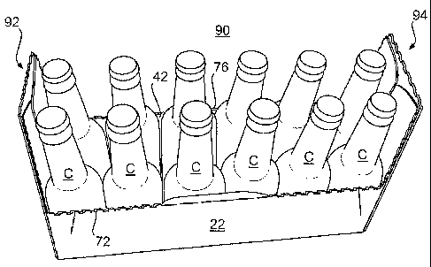
22-27, a dispenser opening is created in a carton 490 by removing or at least
partially separating a section of both a first side panel 420 and a second
side panel
440, and portions of both one end panel 492 and a top panel 430 of the carton
490.
The dispenser section can remain hingedly attached to the carton 490 or be
completely removed from the carton. A portion of the first end panel 492 and a
second end panel 494 of the carton 490 may remain substantially intact to
allow
easy carrying of the opened carton by handle apertures 418 disposed in the end
panels. When opened, the carton 490 provides easy access to articles from the
top, both sides, and one end of the carton.
[0083] FIG. 22 is a plan view of a blank 408 used to form the carton 490
(illustrated in FIG. 23). The blank 408 can be symmetric or partially
symmetric
about a longitudinal centerline CL and about a transverse centerline CT.
Therefore, certain elements in the drawing figures have similar or identical
reference numerals in order to reflect the whole or partial longitudinal and
transverse symmetries. As shown in FIG. 22, the blank 408 comprises a glue
flap
414 which is foldably connected to a rectangular bottom panel 410 at a first
-20-
CA 02599450 2007-08-27
WO 2006/099426 PCT/US2006/009140
transverse fold line 416. The bottom panel 410 is foldably connected to the
first
side panel 420 at a second transverse fold line 421, the top panel 430 is
foldably
connected to the first side panel 420 at a third transverse fold line 431, and
the
second side panel 440 is foldably connected to the top panel 430 at a fourth
transverse fold line 441. Oppositely disposed bottom end flaps 412 are
foldably
connected to the bottom panel 410 at longitudinal fold lines 415. Oppositely
disposed top end flaps 432, 433 are foldably connected to the top panel 430 at
longitudinal fold lines 435. The handle apertures 418 can be included in the
bottom end flaps 412.
[0084] The first side panel 420 can comprise a first upper side panel 424 and
a
first lower side panel 422 foldably connected at a transverse fold line 423.
Oppositely disposed end flaps 428 and 429 are foldably connected to the first
upper side panel 424 at fold lines 454 and 427, respectively. Similarly,
oppositely
disposed end flaps 426 are foldably connected to the first lower side panel
422 at
the oblique fold lines 454. The second side panel 440 can comprise a second
upper side panel 444 and a second lower side panel 442 foldably connected at a
transverse fold line 443. Oppositely disposed end flaps 448 and 449 are
foldably
connected to the second upper side panel 444 at fold lines 454 and 447,
respectively. Similarly, oppositely disposed end flaps 446 are foldably
connected
to the second lower side panel 442 at the oblique fold lines 454. The
longitudinal
fold lines 415, 435 and the fold lines 454, 447, 427 may be straight fold
lines, or
may be offset at one or more locations to account for, for example, blank
thickness.
[0085] The blank 408 includes four diamond corners 450. Two are formed in
the first upper side panel 424, the first lower side panel 422, and the end
flaps
426, 428, 429; these two diamond corners 450 are located at opposite ends of
the
first side panel 420. Similarly, two diamond corners 450 are formed in the
second
upper side panel 444, the second lower side panel 442, and the end flaps 446,
448,
449; these two diamond corners 450 are located at opposite ends of the second
-21-
CA 02599450 2007-08-27
WO 2006/099426 PCT/US2006/009140
side panel 440. At each of these locations, the diamond corners 450 are
defined in
part by transverse fold lines 458, 460, V-shaped fold lines 452, 456, and the
oblique fold line 454.
[0086] According to one aspect of the present embodiment, a dispenser
pattern 470 formed in the blank 408 defines a dispenser section 477. The
dispenser pattern 470 can generally comprise a pattern of lines of disruption
in the
blank 408 that allow the dispenser section 477 to remain hingedly attached or
be
completely removed from the carton 490 (illustrated in FIG. 23). The dispenser
pattern 470 comprises tear lines 472, 474, 476, 479, 480 and a crease line 481
and
further defines an opening section or flap 475 within the dispenser section
477.
The oblique tear lines 472 are located in the first upper side panel 424 and
the
second upper side panel 444. The longitudinal tear line 476 is positioned in
the
top panel 430 and connects the oblique tear lines 472. The tear lines 474 are
located in the end flaps 429, 449 and conform generally to the semi-circular
line
480 and the oblique tear lines 479 when the end panels are formed. The opening
flap 475 is located in the top end flap 433 and comprises the semi-circular
opening tear line 480, the oblique opening tear lines 479, and the T-shaped
opening crease line 481.
[0087] For a carton with a length LC, the length of the dispenser section LD,
or, in other words, the distance that the dispenser section 477 extends into
the top
panel 430, may be measured by the distance between the longitudinal tear line
476
and the longitudinal fold line 435.
[0088] FIG. 23 is a perspective view of one side of the carton 490 erected
from the blank 408, and FIG. 24 is a side view of the same side of the erected
carton 490. The exemplary carton 490 is filled with containers C (not visible
in
FIGS. 23 and 24) in a 2x6 orientation. The first end panel 492 and the second
end panel 494 are formed at opposite ends of the carton 490 by adhering the
end
flaps (illustrated in FIG. 22) together. The dispenser section 477 extends
across
the top panel 430, the side panels 420, 440, and the end panel 492. The
opening
-22-
CA 02599450 2007-08-27
WO 2006/099426 PCT/US2006/009140
flap 475, the tear lines 474, the curved tear line 480, the crease line 481,
and the
oblique tear lines 479 are located in the first end panel 492. The oblique
tear line
472 is located in the first upper side panel 424; a similar oblique tear line
472 is
located in the second upper side panel 444 (illustrated in FIG. 22).
[0089] FIG. 24 illustrates the relationship of the length LD of the dispenser
section 477 to the length Lc of the carton 490, and a dispenser section angle
aD
defined by the oblique lines 472 measured with respect to the plane of the top
panel 430. According to one aspect of the embodiment, the ratio of the length
of
the dispenser section LD to the length of the carton Lc, and the dispenser
section
angle aD, may be selected to provide access to a selected number of containers
C
within the carton 490 (illustrated in FIG. 27). In the exemplary embodiment
illustrated in FIGS. 22-27, the ratio of the length of the dispenser section
LD to
the length of the carton Lc is in the range of about 0.6 to about 0.7 and the
dispenser section angle aD is in the range of about 15 to about 20 .
[0090] FIGS. 25-27 illustrate an exemplary method of opening of the carton
490. Referring to FIG. 25, a user can breach the opening flap 475 (illustrated
in
FIG. 23) along the semi-circular line 480 and depressing the flap 475 at the
opening crease line 481 in order to grasp the dispenser section 477. After the
opening flap 475 has been breached, the dispenser section 477 may be pulled
vertically along the tear lines 474, 479 (illustrated in FIG. 23) in the first
end
panel 492. Then, as shown in FIG. 26, the carton 490 continues to open along
the
dispenser pattern 470 as the dispenser section 477 is pulled vertically along
the
oblique tear lines 472 in the first upper side panel 424 and the second upper
side
panel 444. Once the longitudinal tear line 476 is reached, the dispenser
section
477 can remain hingedly attached to the carton 490, as shown in FIG. 26. In
this
configuration, the dispenser section 477 can be tilted open to remove the
containers C from the carton 490 and then tilted back into its original closed
orientation to cover the containers C so that they are no longer visible.
-23-
CA 02599450 2007-08-27
WO 2006/099426 PCT/US2006/009140
Alternatively, the dispenser section 477 may be completely separated from the
remainder of the carton 490.
[0091] FIG. 27 illustrates the opened carton 490 with the dispenser section
477 removed. The opened carton 490 allows access to and visibility of the
containers C from the top, both sides, and one end of the carton 490. The
carton
490 can be easily carried by the handles 418 in the end panels 492, 494. Even
after opening the carton 490, the carton has high side panels which provide
for
high strength and rigidity. The carton 490 can be stored, for example, inside
a
refrigerator, and provides easy access to, for example, glass or plastic
beverage
bottles. The 2x6 configuration generally will allow the carton 490 to be
placed
and stored in a door shelf of a refrigerator, if desired. Optionally, the
carton 490
can be placed on another shelf in the refrigerator or on another surface,
where the
carton provides easy access to articles from the top, both sides, and one end
of the
carton.
[0092] According to a sixth embodiment of the invention, illustrated by
FIGS. 28-30, a dispenser opening is created in a carton 590 by removing or at
least partially separating a section of both a first side panel 520 and a
second side
panel 540, and portions of both one end panel 592 and a top panel 530 of the
carton 590. When opened, the carton 590 provides easy access to articles from
the top, both sides, and one end of the carton.
[0093] FIG. 28 is a plan view of a blank 508 used to form the carton 590
(illustrated in FIG. 29). As shown in FIG. 28, the blank 508 comprises a glue
flap 514 foldably attached to a rectangular bottom panel 510 at a first
transverse
fold line 516. The bottom panel 510 is foldably connected to the first side
panel
520 at a second transverse fold line 521, the top panel 530 is foldably
connected
to the first side panel 520 at a third transverse fold line 531, and the
second side
panel 540 is foldably connected to the top panel 530 at a fourth transverse
fold
line 541. Oppositely disposed bottom end flaps 512 are foldably connected to
the
bottom panel 510 at longitudinal fold lines 515. Oppositely disposed top end
-24-
CA 02599450 2007-08-27
WO 2006/099426 PCT/US2006/009140
flaps 532, 533 are foldably connected to the top panel 530 at longitudinal
fold
lines 535. Handle apertures 518 can be included in the bottom end flaps 512.
[0094] The first side panel 520 can comprise a first upper side panel 524 and
a
first lower side panel 522 foldably connected at a transverse fold line 523.
Oppositely disposed end flaps 528 and 529 are foldably connected to the first
upper side panel 524 at oblique fold lines 554 and 527, respectively.
Similarly,
oppositely disposed end flaps 526 are foldably connected to the first lower
side
panel 522 at the oblique fold lines 554. The second side panel 540 can
comprise a
second upper side panel 544 and a second lower side panel 542 foldably
connected at a transverse fold line 543. Oppositely disposed end flaps 548 and
549 are foldably connected to the second upper side panel 544 at the oblique
fold
lines 554 and 547, respectively. Similarly, oppositely disposed end flaps 546
are
foldably connected to the second lower side panel 542 at the oblique fold
lines
554. The longitudinal fold lines 515, 535 and the oblique fold lines 554, 527,
547
may be straight fold lines, or may be offset at one or more locations to
account
for, for example, blank thickness.
[0095] The blank 508 includes four diamond corners 550. Two are formed in
the first upper side panel 524, the first lower side panel 522, and the end
flaps
526, 528, 529; these two diamond corners 550 are located at opposite ends of
the
first side panel 520. Similarly, two diamond corners 550 are formed in the
second
upper side panel 544, the second lower side panel 542, and the end flaps 546,
548,
549; these two diamond corners 550 are located at opposite ends of the second
side panel 540. At each of these locations, the diamond corners 550 are
defined in
part by transverse fold lines 558, 560, V-shaped fold lines 552, 556, and the
oblique fold line 554.
[0096] According to one aspect of the present embodiment, a dispenser
pattern 570 formed in the blank 508 defines a dispenser section 577. The
dispenser pattern 570 can be generally similar in shape, construction and
operation to the dispenser pattern 470 illustrated in FIG. 22, and comprises
tear
-25-
CA 02599450 2007-08-27
WO 2006/099426 PCT/US2006/009140
lines 572, 574, 576, 579, 580 and a crease line 581. The dispenser pattern 570
further defines an opening section or flap 575 within the dispenser section
577.
For a carton with a length Lc, the length of the dispenser section LE may be
determined by the distance between the longitudinal tear line 576 and the
longitudinal fold line 535.
[0097] The exemplary methods discussed above for erecting cartons can be
used to erect the carton 590. FIG. 29 illustrates the erected carton 590
filled with
containers C (not visible in FIG. 29) in a 2x6 orientation. The ends of the
carton
590 are closed by a first end panel 592 and a second end panel 594. The
dispenser
section 577 extends across the top panel 530, the side panels 520, 540, and
the
end panel 592. The opening flap 575, the tear lines 574, the semi-circular
tear line
580, the crease line 581 and the oblique tear lines 579 are located in the
first end
panel 592. The oblique tear line 572 is located in the first upper side panel
524; a
similar oblique tear line 572 is located in the second upper side panel 544
(illustrated in FIG. 28).
[0098] FIG. 29 illustrates the relationship of the length of the dispenser
section LE to the length LC of the carton 590, and a dispenser section angle
aE
between the oblique tear lines 572 and the plane of the top panel 530.
According
to one aspect of the present embodiment, the ratio of the length of the
dispenser
section LE to the length of the carton LC, and the dispenser section angle aE,
may
be selected to provide access to selected containers C within the carton 590
(shown in FIG. 30). In the exemplary embodiment illustrated in FIGS. 27-30,
the
ratio of the length of the dispenser section LE to the length of the carton LC
is in
the range of about 0.3 to about 0.4. The dispenser section angle QE is in the
range
of about 25 to about 30 .
[0099] FIGS. 29 and 30 illustrate an exemplary method of opening of the
carton 590. Referring to FIG. 29, a user can breach the opening flap 575 along
the semi-circular tear line 580 and/or the crease line 581 in order to grasp
the
dispenser section 577. After the opening flap 575 has been breached, the
-26-
CA 02599450 2007-08-27
WO 2006/099426 PCT/US2006/009140
dispenser section 577 may be separated from the remainder of the carton 590
along the dispenser pattern 570. Once the longitudinal line 576 is reached,
the
dispenser section 577 can remain hingedly attached to the carton 590.
Alternatively, the dispenser section 577 may be pulled horizontally,
completely
removing the dispenser section 577 from the remainder of the carton 590.
[00100] FIG. 30 illustrates the opened carton and dispensing feature with the
dispenser section 577 removed. The opened carton 590 allows access to and
visibility of the containers C from the top, both sides, and one end of the
carton
590. The carton 590 can be easily carried by the handle apertures 518 in the
end
panels 592, 594 of the carton 590. The carton 590 has high side panels that
provide for high strength and rigidity even after the carton 590 is opened.
[00101] The lengths LD and LE of the dispenser sections 477 and 577,
respectively, illustrated in FIGS. 24 and 29 can be varied to provide
different
dispensing properties to the cartons 490, 590. At the upper limit, the
dispenser
lengths LD and LE can be substantially equal to the length of the carton Lc;
in this
instance, the dispensing sections span the entire length of the carton. In one
aspect of the present invention, the ratio of the length of a dispenser
section to the
length of a carton can range from about 0.2 to 0.9. In another aspect, the
ratio of
the length of a dispenser section to the length of a carton can range from
about 0.3
to 0.7. The dispenser section angles aD and aE illustrated in FIGS. 24 and 29
can range from about 10 to about 70 . In another aspect of the present
invention,
the dispenser section angle can range from about 15 to about 55 . In yet
another
aspect, the dispenser section angle can range from about 15 to about 45 .
[00102] In the above embodiments, the cartons are shown as accommodating
"long-necked" glass beverage bottles. Other types of articles, however, can be
accommodated within cartons according to the present invention. These articles
can include beverage containers such as plastics bottles, metal cans, as well
as
other containers that can be generally cylindrical in shape, such as those
used in
packaging foodstuffs. The dimensions of the blanks and corresponding cartons
-27-
CA 02599450 2007-08-27
WO 2006/099426 PCT/US2006/009140
formed from the blanks may also be altered, for example, to accommodate
various
container forms, shapes, sizes, or quantities.
[00103] For purposes of illustrating the various embodiments of the present
invention, the cartons illustrated above are sized and dimensioned to contain
12
articles or containers in a 2x6 or 3x4 configuration. The present invention is
not
limited to any specific size, dimension, or geometry of carton. For example,
the
present invention would work satisfactorily if sized and shaped to hold
articles of
other configurations, such as 4x3, 2x4, 2x5, 4x6, 4x5, 3x6, 5x6, 6x2, etc.
[00104] The cartons of the exemplary embodiments include four diamond
corners. The term "diamond corner" as used in this specification does not
necessarily indicate a perfect geometric "diamond" shape. To the contrary, the
diamond corners disclosed in this specification have a general diamond shape
as
generally known in the art.
[00105] In the exemplary embodiments discussed above, the blanks can be
formed from clay-coated newsprint (CCN). In general, the blanks can be
constructed of paperboard, having a caliper of at least about 14 points, so
that it is
heavier and more rigid than ordinary paper. For example, caliper of the blank
can
be in the range of about 16 to about 22 point. The blanks, and thus the
cartons,
can also be constructed of other materials, such as cardboard, or any other
material having properties suitable for enabling the carton to function at
least
generally as described above. The first and second sides of the blanks can be
coated with, for example, a clay coating. The clay coating may then be printed
over with product, advertising, price coding, and other information or images.
The blanks may then be coated with a varnish to protect any information
printed
on the blanks. The blanks may also be coated with, for example, a moisture
barrier layer, on either or both sides of the blanks. The blanks can also be
laminated to or coated with one or more sheet-like materials at selected
panels,
panel sections, or the entire blank. Non-limiting examples of sheet-like
materials
-28-
CA 02599450 2007-08-27
WO 2006/099426 PCT/US2006/009140
can include decorative films, protective films, barrier films, or other types
of
plastic films of compositions appropriate for their intended use.
[00106] In accordance with the exemplary embodiments, a fold line can be any
substantially linear, although not necessarily straight, form of weakening
that
facilitates folding therealong. More specifically, but not for the purpose of
narrowing the scope of the present invention, fold lines include: a score
line, such
as lines formed with a blunt scoring knife, or the like, which creates a
crushed
portion in the material along the desired line of weakness; a cut that extends
partially into a material along the desired line of weakness, and/or a series
of cuts
that extend partially into and/or completely through the material along the
desired
line of weakness; and various combinations of these features.
[00107] A tear line can be any substantially linear, although not necessarily
straight, form of weakening that facilitates tearing therealong. Specifically,
but
not for the purpose of narrowing the scope of the present invention, tear
lines
include: a cut that extends partially into the material along the desired line
of
weakness, and/or a series of cuts that extend partially into and/or completely
through the material along the desired line of weakness, or various
combinations
of these features. As a more specific example, one type of tear line is in the
form
of a series of cuts that extend completely through the material, with adjacent
cuts
being spaced apart slightly so that small somewhat bridge-like pieces of the
material (e.g., `nicks') are defined between adjacent cuts. The nicks are
broken
during tearing along the tear line. Such a tear line that includes nicks can
also be
referred to as a cut line, since the nicks typically are a relatively small in
relation
to the cuts.
[00108] The term "line" as used herein includes not only straight lines, but
also
other types of lines such as curved, curvilinear or angularly displaced lines,
and
combinations of adjacent line segments.
-29-
CA 02599450 2007-08-27
WO 2006/099426 PCT/US2006/009140
[00109] The above embodiments may be described as having one or panels
adhered together by glue. The term "glue" is intended to encompass all manner
of
adhesives commonly used to secure paperboard carton panels in place.
[00110] The foregoing description of the invention illustrates and describes
the
present invention. Additionally, the disclosure shows and describes only
selected
embodiments of the invention, but it is to be understood that the invention is
capable of use in various other combinations, modifications, and environments
and is capable of changes or modifications within the scope of the inventive
concept as expressed herein, commensurate with the above teachings, and/or
within the skill or knowledge of the relevant art.
-30-