Language selection

Search

Patent 2600819 Summary

Third-party information liability

Some of the information on this Web page has been provided by external sources. The Government of Canada is not responsible for the accuracy, reliability or currency of the information supplied by external sources. Users wishing to rely upon this information should consult directly with the source of the information. Content provided by external sources is not subject to official languages, privacy and accessibility requirements.

Claims and Abstract availability

Any discrepancies in the text and image of the Claims and Abstract are due to differing posting times. Text of the Claims and Abstract are posted:

  • At the time the application is open to public inspection;
  • At the time of issue of the patent (grant).
(12) Patent Application: (11) CA 2600819
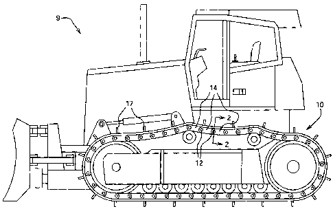
(54) English Title: CARTRIDGE FOR USE AS JOINT IN ENDLESS TRACK CHAIN AND ASSOCIATED METHOD
(54) French Title: MANCHON POUR UTILISATION COMME JOINT DANS UNE CHENILLE ET METHODE D'UTILISATION
Status: Deemed Abandoned and Beyond the Period of Reinstatement - Pending Response to Notice of Disregarded Communication
Bibliographic Data
(51) International Patent Classification (IPC):
  • B62D 55/21 (2006.01)
  • B62D 55/32 (2006.01)
(72) Inventors :
  • MULLIGAN, PATRICK JOHN (United States of America)
  • BIHL, DANIEL FREDERICK (United States of America)
  • SCHRAUBEN, KEVIN DOUGLAS (United States of America)
  • WODRICH, TIMOTHY DIRK (United States of America)
(73) Owners :
  • DEERE & COMPANY
(71) Applicants :
  • DEERE & COMPANY (United States of America)
(74) Agent: BORDEN LADNER GERVAIS LLP
(74) Associate agent:
(45) Issued:
(22) Filed Date: 2007-09-06
(41) Open to Public Inspection: 2008-03-22
Examination requested: 2012-09-05
Availability of licence: N/A
Dedicated to the Public: N/A
(25) Language of filing: English

Patent Cooperation Treaty (PCT): No

(30) Application Priority Data:
Application No. Country/Territory Date
11/525,367 (United States of America) 2006-09-22

Abstracts

English Abstract


A cartridge is provided for use as a joint between links of an endless track
chain. The cartridge is designed for assembly prior to attachment of the
cartridge to
the links. An associated method is disclosed.


Claims

Note: Claims are shown in the official language in which they were submitted.

-6-
Claims:
1. A method of assembling a track chain, comprising:
forming a cartridge comprising a bushing, a collar, a seal captured between
the bushing and the collar, and a pin received in the bushing and the collar
such that
the pin and the bushing are relatively rotatable and the pin and the collar
are fixed to
one another, and
after forming the cartridge, introducing the cartridge to a first link and a
second link so as to fix the bushing and the first link to one another and fix
the collar
and the second link to one another such that the cartridge joins the first
link and the
second link for relative rotation therebetween.
2. The method of claim 1, wherein the introducing comprises inserting the
collar into a bore of the second link so as to establish a press-fit
therebetween.
3. The method of claim 1, wherein the forming comprises retaining the
collar on the pin with a retaining ring.
4. The method of claim 1, wherein the introducing comprises retaining the
collar in a bore of the second link with a retaining ring.
5. The method of claim 1, wherein the introducing comprises retaining the
collar in a bore of the second link with a lip of the second link.
6. The method of claim 1, wherein the collar is a first collar and the seal is
a second seal, the forming comprises forming the cartridge so as to comprise a
second collar and a second seal such that the first and second collars are
disposed
along the pin at opposite ends thereof and the second collar cooperates with
the
bushing to capture the second seal between the second collar and the bushing,
the
introducing comprises introducing the cartridge to a third link and a fourth
link so as
to fix the bushing and the third link to one another and fix the second collar
and the
fourth link to one another such that the cartridge joins the third link and
the fourth link
for relative rotation therebetween.
7. The method of claim 6, wherein the introducing comprises inserting the
first collar into a bore of the second link so as to establish a press-fit
therebetween
and the second collar into a bore of the fourth link so as to establish a
press-fit

-7-
therebetween.
8. An endless track chain, comprising:
a first link and a second link, and
a cartridge joining the first and second links for relative rotation
therebetween,
the cartridge comprising a pin, a bushing disposed between the first link and
the pin
such that the bushing is fixed to the first link and receives the pin for
relative rotation
between the bushing and the pin, a seal, and a collar cooperating with the
bushing to
capture the seal therebetween and disposed between the second link and the pin
so
as to be fixed to the second link and the pin, the collar being distinct from
the second
link for assembly of the cartridge prior to introduction of the cartridge to
the first and
second links during assembly of the track chain.
9. The endless track chain of claim 8, wherein the cartridge comprises a
spacer ring disposed between the collar and the bushing so as to space the
collar
and the bushing apart from one another.
10. The endless track chain of claim 8, wherein the collar comprises a
groove, and the second link comprises a lip extending into the groove.
11. The endless track chain of claim 8, comprising a retaining ring acting at
an interface between the collar and the second link.
12. The endless track chain of claim 8, wherein the pin comprises a
groove, and the collar comprises a lip extending into the groove.
13. The endless track chain of claim 8, comprising a retaining ring acting at
an interface between the collar and the pin.
14. The endless track chain of claim 8, wherein the collar is a first collar
and the seal is a second seal, further comprising a third link, a fourth link,
a second
seal, and a second collar, the third link being fixed to the bushing, the
first and
second collars being disposed along the pin at opposite ends thereof, the
second
collar cooperating with the bushing to capture the second seal between the
second
collar and the bushing, the second collar being disposed between the fourth
link and
the pin so as to be fixed to the fourth link and the pin, the second collar
being distinct
from the fourth link.
15. The endless track chain of claim 14, wherein the first collar is press-

-8-
fitted into the second link, and the second collar is press-fitted into the
fourth link.
16. A cartridge for use as a joint to join first and second links of an
endless
track chain for relative rotation between the first and second links, the
cartridge
comprising:
a pin,
a bushing receiving the pin for relative rotation therebetween, the bushing
being adapted to be received by the first link so as to be fixed thereto,
a seal, and
a collar cooperating with the bushing to capture the seal therebetween and
receiving the pin so as to be fixed thereto, the collar being adapted to be
received by
the second link so as to be fixed thereto after formation of the cartridge.
17. The cartridge of claim 16, wherein the collar comprises a groove
formed in a radially outer surface of the collar.
18. The cartridge of claim 16, comprising a retaining pin acting between
the collar and the pin.
19. The cartridge of claim 16, wherein the seal is a first seal and the collar
is a first collar, further comprising a second seal and a second collar, the
bushing
being adapted to be received by the third link so as to be fixed thereto, the
first and
second collars being disposed along the pin at opposite ends thereof on either
side
of the bushing in spaced-apart relation to the bushing, the second collar
cooperating
with the bushing to capture the second seal between the second collar and the
bushing, the second collar being fixed to the pin and adapted to be received
by the
fourth link so as to be fixed thereto after formation of the cartridge.

Description

Note: Descriptions are shown in the official language in which they were submitted.


CA 02600819 2007-09-06
-1-
CARTRIDGE FOR USE AS JOINT IN ENDLESS TRACK CHAIN
AND ASSOCIATED METHOD
Field of the Disclosure
[0001] The present disclosure relates to joints between track chain links and
methods associated therewith.
Background of the Disclosure
[0002] Endless track chains are used on track-type vehicles. The track chain
includes a number of links and a joint joining adjacent links for relative
rotation
therebetween.
Summary of the Disclosure
[0003] According to the present disclosure, there is provided a cartridge for
use as
a joint between links of an endless track chain for relative rotation between
the links.
The cartridge is designed for assembly prior to attachment of the cartridge to
the
links, promoting the effectiveness of the seal(s) of the joint. An associated
method is
disclosed.
[0004] Illustratively, the cartridge comprises a pin, a bushing, first and
second
seals, and first and second collars. The pin is received in the bushing for
relative
rotation between the pin and the bushing. A pair of first links are fixed to
the bushing
at opposite ends of the bushing. The first and second collars receive the pin
at
opposite ends thereof on either side of the bushing to respectively capture
the first
and second seals between the collars and the bushing. The collars are fixed to
the
pin and a pair of second links but are distinct from the pin and the second
links to
facilitate formation of the cartridge prior to attachment of the cartridge to
the links.
Such pre-assembly of the cartridge promotes the integrity of the seals.
[0005] The above and other features will become apparent from the following
description and the attached drawings.
Brief Description of the Drawings
[0006] The detailed description of the drawings refers to the accompanying
figures
in which:
[0007] FIG. 1 is a side elevation view of a track-type vehicle;

CA 02600819 2007-09-06
-2-
[0008] FIG. 2 is a sectional view taken along lines 2-2 of FIG. 1 showing a
cartridge acting as a joint between a number of links of a track chain; and
[0009] FIG. 3 is a sectional view showing an alternative cartridge which may
be
used in place of the cartridge of FIG. 2.
Detailed Description of the Drawings
[0010] Referring to FIG. 1, there is shown a track-type vehicle 9 that has an
endless track chain 10 for propulsion of the vehicle 9. The vehicle 9 may be
any
type of vehicle with a track chain. The track chain 10 includes a plurality of
links 14
to which one or more traction elements 17 are attached for engagement with a
surface underlying the vehicle 9. The track chain 10 further includes a
cartridge 12
acting as a joint joining adjacent links 14 for relative rotation therebetween
upon
movement of the track chain 10 about its closed-loop path. The cartridge 12 is
formed prior to introduction to the links 14. After the cartridge 12 is
formed, it is
introduced to the links 14a and attached thereto. Such pre-assembly of the
cartridge
12 promotes the integrity of seals in the cartridge 12 and thus the longevity
of the
cartridge 12.
[0011] Referring to FIG. 2, there is shown a sectional view of the endless
track
chain 10. Attached to each cartridge 12 are a pair of first links 14a of the
links 14
and a pair of second links 14b of the links 14. The cartridge 12 acts as a
joint joining
the first links 14a and the second links 14b for relative rotation between the
first links
14a and the second links 14b.
[0012] The cartridge 12 has a bushing 18 to which the first links 14a are
fixed at
opposite ends of the bushing 18. Exemplarily, the bushing 18 is press-fit into
a bore
19 of each link 14.
[0013] A pin 20 is received in the bushing 18. Lubricant (e.g., oil) from a
lubricant
cavity 22 formed in the pin 20 lubricates the interface between the bushing 18
and
the pin 20 for relative rotation between the bushing 18 and the pin 20. The
lubricant
can be injected into the cavity 22 via a channel 24 formed in a compressible
body 25
upon removal of a plug 26 that normally closes the channel 24.
[0014] The cartridge 12 further includes a pair of collars 28. The collars 28
are

CA 02600819 2007-09-06
-3-
located at opposite ends of the pin 20 on either side of the bushing 18. Each
collar
28 cooperates with the bushing 18 to capture therebetween a seal 30 designed
to
inhibit leakage of the lubricant and inhibit contamination of the lubricant by
ingress of
debris. Illustratively, the seal 30 has a seal element 31 (made, for example,
of
polyurethane) for contacting the bushing 18 and a seal-loading member 33
(made,
for example, of nitrile) for loading the seal element 31 against the bushing
18. It is to
be understood that the seal 30 may be configured in a wide variety of ways,
the
particular embodiment illustrated being just one of those possible ways. A
spacer
ring 32 is located between each collar 28 and the bushing 18 to space the
collar 28
slightly apart from the bushing 18 for relative rotation between the bushing
18 and
the collar 28.
[0015] Each collar 28 is disposed between, and fixed to, an second link 14b
and an
end of the pin 20 for rotation with the link 14b and pin 20 relative to the
bushing 18
and the first links 14. The collar 28 is received in a bore 34 of the link 14b
such that
a radially outer surface of the collar 28 mates with, and is press-fit into,
the bore 34
and a radially inner surface of the collar 28 mates with a radially outer
surface of the
pin 20 which is press-fit into the collar 28.
[0016] Retaining rings 36, 38 at each end of the cartridge 12 act to retain
the
cartridge 12 in place. The retaining ring 36 acts at an interface between the
collar 28
and the bore 34. The ring 36 is received by a groove 40 formed in the radially
outer
surface of the collar 28. The retaining ring 38 acts at an interface between
the collar
28 and the pin 20. A lip 42 of the collar 28 extends into a groove 44 formed
in the
pin 20 to act against the ring 38 and a shoulder of the groove 44 to promote
retention
of the components of the cartridge 12.
[0017] The cartridge 12 is formed before introduction of the cartridge 12 to
the links
14, 14b. During formation of the cartridge 12, the pin 20 is inserted into the
bushing
18 and the spacer rings 32 are inserted into the ends of the bushing 18. The
ends of
the pin 20 are inserted into the collars 28 such that the lips 42 are received
in the
grooves 44, capturing the seals 30 between the collars 28 and the ends of the
bushing 18. Retaining rings 38 are installed to help hold the collars 28 in
place.
[0018] After formation of the cartridge 12, the cartridge 12 is introduced to
the links

CA 02600819 2007-09-06
-4-
14, 14b. The cartridge 12 is inserted into the bores 19 of the links 14a and
the bores
34 of the links 14b so as to establish a press-fit between the bushing 18 and
the links
14a and a press-fit between the collars 28 and the links 14b. The retaining
rings 36
are then installed. Lubricant may be injected into the cartridge 12 before or
after
introduction of the cartridge 12 to the links 14, 14b.
[0019] Referring to FIG. 3, an endless track chain 110 may be used on the
vehicle
9 in place of the track chain 10. Some of the components of the track chain
110 are
similar to those of the track chain 10 such that identical reference numbers
refer to
similar components, the main differences being discussed below.
[0020] The track chain 110 has a cartridge 112 which acts as a joint joining
the
pair of first links 14a and the pair of second links 14b. The cartridge 112 is
formed
prior to introduction to the links 14, 14b. After the cartridge 112 is formed,
it is
introduced to the links 14, 14b and attached thereto. Such pre-assembly of the
cartridge 112 promotes the integrity of the seals 30 in the cartridge 112 and
thus the
longevity of the cartridge 112.
[0021] The cartridge 112 has a bushing 18 that is fixed to the links 14a and
receives the pin 20 for relative rotation between the bushing 18 and the pin
20.
Lubricant injected into the cavity 22 via the channel 24 lubricates the
interface
between the bushing 18 and the pin 20.
[0022] The cartridge 112 includes a pair of collars 128. The collars 128 are
located
at opposite ends of the pin 20 on either side of the bushing. Each collar 128
cooperates with the bushing 18 to capture therebetween a seal 30 and is spaced
slightly apart from the bushing 18 by a spacer ring 32 for relative rotation
between
the collar 128 and the bushing 18.
[0023] Each collar 128 is disposed between, and fixed to, an second link 14b
and
an end of the pin 20 for rotation with the link 14b and pin 20 relative to the
bushing
18 and the first links 14. The collar 128 is received in the bore 34 of the
link 14b
such that a radially outer surface of the collar 128 mates with, and is press-
fit into,
the bore 34 and a radially inner surface of the collar 128 mates with a
radailly outer
surface of the pin 20 which is press-fit into the collar 128. The link 14b has
a lip 150
extending radially inwardly into a groove 140 formed in the radially outer
surface of

CA 02600819 2007-09-06
-5-
the collar 128 to promote retention of the cartridge 112 in place. A retaining
ring 138
acts at the interface of the pin 20 and a shoulder of a groove 152 formed in
the
radially inner surface of the collar 128 for retention of the components of
the
cartridge 112.
[0024] The cartridge 112 is formed before introduction of the cartridge 112 to
the
links 14, 14b. During formation of the cartridge 112, the pin 20 is inserted
into the
bushing 18 and the spacer rings 32 are inserted into the end of the bushing
18. The
ends of the pin 20 are inserted into the collars 128 so as to capture the
seals 30
between the collars 128 and the ends of the bushing 18. The retaining rings
138 are
then installed.
[0025] After formation of the cartridge 112, the cartridge 112 is introduced
to the
links 14, 14b. The cartridge 112 is inserted into the bores 19 of the links
14a and the
bores 34 of the links 14b so as to establish a press-fit between the bushing
18 and
the links 14a and a press-fit between the collars 128 and the links 14b. In
particular,
one of the second links 14b may be removed or otherwise moved out of the way
to
avoid interference with the lip 150 thereof so as to facilitate insertion of
the cartridge
112 into the two first links 14a and the other second link, after which the
remaining
second link 14b may be pressed onto the respective collar 128. Lubricant may
be
injected into the cartridge 112 before or after introduction of the cartridge
12 to the
links 14, 14b.
[0026] While the disclosure has been illustrated and described in detail in
the
drawings and foregoing description, such an illustration and description is to
be
considered as exemplary and not restrictive in character, it being understood
that
illustrative embodiments have been shown and described and that all changes
and
modifications that come within the spirit of the disclosure are desired to be
protected.
It will be noted that alternative embodiments of the present disclosure may
not
include all of the features described yet still benefit from at least some of
the
advantages of such features. Those of ordinary skill in the art may readily
devise
their own implementations that incorporate one or more of the features of the
present
disclosure and fall within the spirit and scope of the present invention as
defined by
the appended claims.

Representative Drawing
A single figure which represents the drawing illustrating the invention.
Administrative Status

2024-08-01:As part of the Next Generation Patents (NGP) transition, the Canadian Patents Database (CPD) now contains a more detailed Event History, which replicates the Event Log of our new back-office solution.

Please note that "Inactive:" events refers to events no longer in use in our new back-office solution.

For a clearer understanding of the status of the application/patent presented on this page, the site Disclaimer , as well as the definitions for Patent , Event History , Maintenance Fee  and Payment History  should be consulted.

Event History

Description Date
Inactive: Dead - Final fee not paid 2016-03-04
Application Not Reinstated by Deadline 2016-03-04
Deemed Abandoned - Failure to Respond to Maintenance Fee Notice 2015-09-08
Deemed Abandoned - Conditions for Grant Determined Not Compliant 2015-03-04
Notice of Allowance is Issued 2014-09-04
Letter Sent 2014-09-04
Notice of Allowance is Issued 2014-09-04
Inactive: Approved for allowance (AFA) 2014-08-28
Inactive: Q2 passed 2014-08-28
Amendment Received - Voluntary Amendment 2014-05-13
Inactive: S.30(2) Rules - Examiner requisition 2013-11-15
Inactive: Report - QC passed 2013-11-01
Letter Sent 2012-09-25
Request for Examination Requirements Determined Compliant 2012-09-05
All Requirements for Examination Determined Compliant 2012-09-05
Request for Examination Received 2012-09-05
Application Published (Open to Public Inspection) 2008-03-22
Inactive: Cover page published 2008-03-21
Inactive: IPC assigned 2008-02-05
Inactive: First IPC assigned 2008-02-05
Inactive: IPC assigned 2008-02-05
Inactive: Filing certificate - No RFE (English) 2007-10-12
Application Received - Regular National 2007-10-12

Abandonment History

Abandonment Date Reason Reinstatement Date
2015-09-08
2015-03-04

Maintenance Fee

The last payment was received on 2014-08-22

Note : If the full payment has not been received on or before the date indicated, a further fee may be required which may be one of the following

  • the reinstatement fee;
  • the late payment fee; or
  • additional fee to reverse deemed expiry.

Patent fees are adjusted on the 1st of January every year. The amounts above are the current amounts if received by December 31 of the current year.
Please refer to the CIPO Patent Fees web page to see all current fee amounts.

Fee History

Fee Type Anniversary Year Due Date Paid Date
Application fee - standard 2007-09-06
MF (application, 2nd anniv.) - standard 02 2009-09-08 2009-08-19
MF (application, 3rd anniv.) - standard 03 2010-09-07 2010-08-23
MF (application, 4th anniv.) - standard 04 2011-09-06 2011-08-19
MF (application, 5th anniv.) - standard 05 2012-09-06 2012-08-21
Request for examination - standard 2012-09-05
MF (application, 6th anniv.) - standard 06 2013-09-06 2013-08-22
MF (application, 7th anniv.) - standard 07 2014-09-08 2014-08-22
Owners on Record

Note: Records showing the ownership history in alphabetical order.

Current Owners on Record
DEERE & COMPANY
Past Owners on Record
DANIEL FREDERICK BIHL
KEVIN DOUGLAS SCHRAUBEN
PATRICK JOHN MULLIGAN
TIMOTHY DIRK WODRICH
Past Owners that do not appear in the "Owners on Record" listing will appear in other documentation within the application.
Documents

To view selected files, please enter reCAPTCHA code :


To view images, click a link in the Document Description column. To download the documents, select one or more checkboxes in the first column and then click the "Download Selected in PDF format (Zip Archive)" or the "Download Selected as Single PDF" button.

List of published and non-published patent-specific documents on the CPD .

If you have any difficulty accessing content, you can call the Client Service Centre at 1-866-997-1936 or send them an e-mail at CIPO Client Service Centre.


Document
Description 
Date
(yyyy-mm-dd) 
Number of pages   Size of Image (KB) 
Description 2014-05-12 5 225
Claims 2014-05-12 3 90
Abstract 2007-09-05 1 6
Description 2007-09-05 5 234
Claims 2007-09-05 3 122
Drawings 2007-09-05 3 118
Representative drawing 2008-02-28 1 16
Filing Certificate (English) 2007-10-11 1 170
Reminder of maintenance fee due 2009-05-06 1 112
Reminder - Request for Examination 2012-05-07 1 118
Acknowledgement of Request for Examination 2012-09-24 1 177
Commissioner's Notice - Application Found Allowable 2014-09-03 1 161
Courtesy - Abandonment Letter (NOA) 2015-04-28 1 164
Courtesy - Abandonment Letter (Maintenance Fee) 2015-11-02 1 172