Language selection

Search

Patent 2600889 Summary

Third-party information liability

Some of the information on this Web page has been provided by external sources. The Government of Canada is not responsible for the accuracy, reliability or currency of the information supplied by external sources. Users wishing to rely upon this information should consult directly with the source of the information. Content provided by external sources is not subject to official languages, privacy and accessibility requirements.

Claims and Abstract availability

Any discrepancies in the text and image of the Claims and Abstract are due to differing posting times. Text of the Claims and Abstract are posted:

  • At the time the application is open to public inspection;
  • At the time of issue of the patent (grant).
(12) Patent Application: (11) CA 2600889
(54) English Title: SEPARATOR APPARATUS
(54) French Title: APPAREIL DE SEPARATION
Status: Deemed Abandoned and Beyond the Period of Reinstatement - Pending Response to Notice of Disregarded Communication
Bibliographic Data
(51) International Patent Classification (IPC):
  • B04C 03/06 (2006.01)
  • B01D 21/26 (2006.01)
  • B01D 45/16 (2006.01)
(72) Inventors :
  • GOH, KIM (Australia)
  • HAY, PETER STEWART (Australia)
  • BROWN, GARY JAMES (Australia)
(73) Owners :
  • ALCOA OF AUSTRALIA LIMITED
(71) Applicants :
  • ALCOA OF AUSTRALIA LIMITED (Australia)
(74) Agent: RICHES, MCKENZIE & HERBERT LLP
(74) Associate agent:
(45) Issued:
(86) PCT Filing Date: 2006-02-28
(87) Open to Public Inspection: 2006-09-08
Availability of licence: N/A
Dedicated to the Public: N/A
(25) Language of filing: English

Patent Cooperation Treaty (PCT): Yes
(86) PCT Filing Number: PCT/AU2006/000257
(87) International Publication Number: AU2006000257
(85) National Entry: 2007-08-30

(30) Application Priority Data:
Application No. Country/Territory Date
2005900972 (Australia) 2005-03-02

Abstracts

English Abstract


Abstract A separator apparatus (10) characterised by a fluid inlet (12), a
fluid outlet (14), a separated solids outlet (30) and a swirl vane (22), the
swirl vane (22) being located down stream of the fluid inlet (12) but upstream
of the fluid outlet (14) and separated solids outlet (30), the swirl vane (22)
further being arranged so as to impart to the fluid flow passing therethrough
a flow such that entrained particles move radially outward due to inertia, the
fluid outlet (14) being arranged in-line with the fluid inlet (12) and swirl
vane (22) whereas the solids outlet (30) is fed by a radially arranged
collector.


French Abstract

La présente invention concerne un appareil de séparation (10) caractérisé par une entrée de fluide (12), une sortie de fluide (14), une sortie de solides (30) séparée et une vanne tourbillonnante (22), la vanne tourbillonnante (22) étant située en aval de l~entrée de fluide (12) mais en amont de la sortie de fluide (14) et de la sortie de solides (30) séparée, la vanne tourbillonnante (22) étant en outre disposée de façon à transmettre à l~écoulement de fluide la traversant un écoulement tel que les particules entraînées se déplacent radialement vers l~extérieur en raison de l~inertie, la sortie de fluide (14) étant alignée avec l~entrée de fluide (12) et la vanne tourbillonnante (22) tandis que la sortie de solides (30) est alimentée par un collecteur disposé dans le plan radial.

Claims

Note: Claims are shown in the official language in which they were submitted.

-6-
Claims
1. A separator apparatus characterised by a fluid inlet, a fluid outlet, a
separated solids outlet and a swirl vane, the swirl vane being located down
stream of the fluid inlet but upstream of the fluid outlet and separated
solids
outlet, the swirl vane further being arranged so as to impart to the fluid
flow
passing therethrough a flow such that entrained particles move radially
outward due to inertia, the fluid outlet being arranged in-line with the fluid
inlet and swirl vane whereas the solids outlet is fed by a radially arranged
collector.
2. An apparatus according to claim 1, wherein the fluid outlet is of the same
gauge as the fluid inlet.
3. An apparatus according to claim I or 2, wherein the swirl vain is provided
in a
helical arrangement arranged axially along the flow path of the fluid inlet
and
fluid outlet.
4. An apparatus according to any one of the preceding claims, wherein the
collector is offset with respect to the axial orientation of the fluid inlet
and fluid
outlet so as to enhance flow of entrained particles to the solids outlet.
5. An apparatus according to any one of the preceding claims, wherein the
swirl
vane is provided in the form of four individual vanes arranged in a helical
manner about a central axis of the fluid-flow path.
6. In accordance with the present invention there is further provided a method
for the introduction of a separator apparatus into an existing fluid flow
line,
the method characterised by the removal of a portion of the existing fluid
flow
line and the introduction of an in-line separator apparatus as defined
hereinabove.
7. A separator apparatus substantially as hereinbefore described with
reference
to the accompanying drawings.

-7-
8. A method for the introduction of a separator apparatus into an existing
fluid
flow line, the method being substantially as hereinbefore described with
reference to the accompanying drawings.

Description

Note: Descriptions are shown in the official language in which they were submitted.


CA 02600889 2007-08-30
WO 2006/092006 PCT/AU2006/000257
-1-
"Separator Apparatus"
Field of the Invention
The present invention relates to a separator apparatus. More particularly, the
separator apparatus of the present invention is able to be provided "in-line"
in a
process stream. The separator apparatus of the present invention has further
particular application in circumstances requiring removal of solids entrained
in
process streams that are not suited to use of other forms of filtering.
Background Art
The most commonly utilised separation apparatus for dust collection, or the
separation of solids entrained in a gas stream, is the cyclone separator. In a
typical separator, gas with entrained solids, such as dust, is directed
tangentially
into the top of a conical chamber. Entrained dust particles move toward the
outside of the separator and are funnelled downwardly into a receiver. The
clean
gas is removed from the chamber through an upper central opening.
Importantly, cyclones are used to remove both solids and liquids from gases.
In many circumstances it is necessary to retro-fit a separator into an
existing
fluid-flow line. Due to the physical constraints of the existing flow-line,
with
regard to space and orientation, it may not be possible to utilise a typical
cyclone
separator. In such circumstances filters of various forms may be utilised.
However, in circumstances requiring minimum heat loss, filters are often
inappropriate.
The separator apparatus of the present invention has as one object thereof to
overcome substantially the above mentioned problems associated with the prior
art.
The preceding discussion of the background art is intended to facilitate an
understanding of the present invention only. It should be appreciated that the
discussion is not an acknowledgement or admission that any of the material

CA 02600889 2007-08-30
WO 2006/092006 PCT/AU2006/000257
-2-
referred to was part of the common general knowledge in Australia or any other
country or region as at the priority date of the application.
Throughout the specification, unless the context requires otherwise, the word
"comprise" or variations such as "comprises" or "comprising", will be
understood
to imply the inclusion of a stated integer or group of integers but not the
exclusion of any other integer or group of integers.
Disclosure of the Invention
In accordance with the present invention there is provided a separator
apparatus
characterised by a fluid inlet, a fluid outlet, a separated solids outlet and
a swirl
vane, the swirl vane being located down stream of the fluid inlet but upstream
of
the fluid outlet and separated solids outlet, the swirl vane further being
arranged
so as to impart to the fluid flow passing therethrough a flow such that
entrained
particles move radially outward due to inertia, the fluid outlet being
arranged in-
line with the fluid inlet and swirl vane whereas the solids outlet is fed by a
radially
arranged collector.
Preferably, the fluid outlet is of the same gauge as the fluid inlet.
Still preferably, the swirl vain is provided in a helical arrangement arranged
axially along the flow path of the fluid inlet and fluid outlet.
Still further preferably, the collector is offset with respect to the axial
orientation
of the fluid inlet and fluid outlet so as to enhance flow of entrained
particles to the
solids outlet.
In one form of the present invention the swirl vane is provided in the form of
four
individual vanes arranged in a helical manner about a central axis of the
fluid-
flow path.
In accordance with the present invention there is further provided a method
for
the introduction of a separator apparatus into an existing fluid flow line,
the

CA 02600889 2007-08-30
WO 2006/092006 PCT/AU2006/000257
-3-
method characterised by the removal of a portion of the existing fluid flow
line
and the introduction of an in-line separator apparatus as defined hereinabove.
Brief Description of the Drawings
The separator apparatus of the present invention will now be described, by way
of example only, with reference to one embodiment thereof and the
accompanying drawings, in which:-
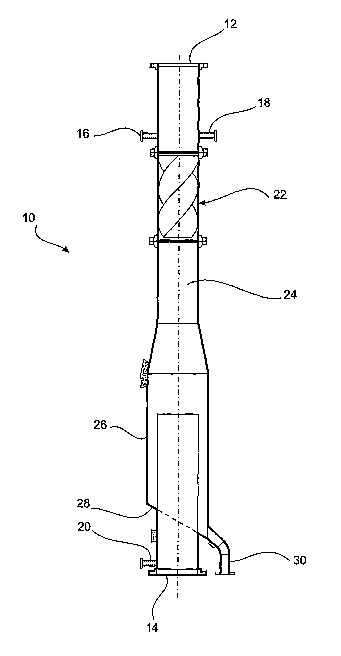
Figure 1 is a cross-sectional side view of a separator apparatus in
accordance with the present invention;
Figure 2 is a cross-sectional side view of a swirl vane provided in the
separator apparatus of Figure 1; and
Figure 3 is a cross-sectional axial view of the swirl vane taken at B-B of
Figure 2.
Best Mode(s) for Carrying Out the Invention
In Figure 1 there is shown a separator apparatus 10 in accordance with the
present invention. The separator apparatus 10 is provided in a form suitable
for
introduction into a fluid low line in circumstances requiring the removal of
entrained solids therefrom.
The separator apparatus 10 comprises a fluid inlet 12 and a fluid outlet 14.
Substantially adjacent the fluid inlet 12 is provided a temperature indicator
16
and a pressure indicator 18. A further pressure indicator 20 is provided
adjacent
the fluid outlet 14.
The separator apparatus 10 further comprises a fluid flow modulating portion
or
swirl vane 22. The swirl vane 22 is provided within the bore of a piping 24
that
forms it and the remainder of the separator apparatus 10 in large part.

CA 02600889 2007-08-30
WO 2006/092006 PCT/AU2006/000257
-4-
Down stream of the swirl vane portion 22 is provided a collector, the
collector
comprising a radially flared portion 26 of the separator apparatus and an off-
set
collecting surface 28, which in turn feeds solids to a solids outlet 30. The
fluid
outlet 14 projects upstream through the collector surface 28 and terminates at
a
point generally mid-way between the up-stream radial flared portion 26 and the
surface 28.
In Figures 2 and 3 there is shown the swirl vane portion 22 comprising a pipe
32
defining a bore 34, an inlet end 36 and an outlet end 38. Within the bore 34
is
located a swirl vane 40 comprising 4 intersecting vanes 42, the intersection
thereof is provided co-axially within the bore 34 of the pipe 32. The vanes 42
are
arranged so as to describe a helical structure within the pipe 32.
In use, fluid flowing into the separator apparatus 10 has induced therein a
swirling or rotational movement whereby entrained solids move radially outward
due to inertia as they pass downstream of the swirl vane portion 22. The solid
particles generally move into the flared portion 26 and are collected against
the
collector wall 28 and fed to the solids outlet 30, whilst fluid containing
substantially less entrained solids pass into the piping comprising the fluid
outlet
14 and which is arranged co-axially with the swirl vane portion 22 and fluid
inlet
12.
The separator apparatus 10 of the present invention is arranged such that it
is
substantially in-line or co-axial with regard to existing fluid flow, thereby
allowing
it to be inserted into an existing fluid flow line with minimal re-engineering
required.
Further, the separator apparatus 10 of the present invention will result in
minimal
heat loss from a fluid flow, particularly when compared with typical filter
means
that might otherwise be utilised. Largely for this reason the applicant
considers
the separator apparatus 10 to have particular application in the Bayer process
when installed in vapour lines between flash tanks used for flashing hot
pregnant
liquor and shell and tube heat exchangers which utilise the hot vapour from
flashing to heat spent liquor. These heat exchangers are subject to clogging
and

CA 02600889 2007-08-30
WO 2006/092006 PCT/AU2006/000257
-5-
scale build up, which may result in inefficient heat exchange and require
costly
and difficult maintenance. The provision of separator apparatus' 10 in these
vapour lines is expected to significantly improve the performance of the heat
exchangers over time.
Modifications and variations such as would be apparent to the skilled
addressee
are considered to fall within the scope of the present invention.

Representative Drawing
A single figure which represents the drawing illustrating the invention.
Administrative Status

2024-08-01:As part of the Next Generation Patents (NGP) transition, the Canadian Patents Database (CPD) now contains a more detailed Event History, which replicates the Event Log of our new back-office solution.

Please note that "Inactive:" events refers to events no longer in use in our new back-office solution.

For a clearer understanding of the status of the application/patent presented on this page, the site Disclaimer , as well as the definitions for Patent , Event History , Maintenance Fee  and Payment History  should be consulted.

Event History

Description Date
Application Not Reinstated by Deadline 2011-02-28
Time Limit for Reversal Expired 2011-02-28
Deemed Abandoned - Failure to Respond to Maintenance Fee Notice 2010-03-01
Amendment Received - Voluntary Amendment 2008-06-05
Letter Sent 2008-04-11
Inactive: Single transfer 2008-01-22
Inactive: Cover page published 2007-11-20
Inactive: Notice - National entry - No RFE 2007-11-15
Inactive: First IPC assigned 2007-10-16
Application Received - PCT 2007-10-15
National Entry Requirements Determined Compliant 2007-08-30
Application Published (Open to Public Inspection) 2006-09-08

Abandonment History

Abandonment Date Reason Reinstatement Date
2010-03-01

Maintenance Fee

The last payment was received on 2009-02-12

Note : If the full payment has not been received on or before the date indicated, a further fee may be required which may be one of the following

  • the reinstatement fee;
  • the late payment fee; or
  • additional fee to reverse deemed expiry.

Patent fees are adjusted on the 1st of January every year. The amounts above are the current amounts if received by December 31 of the current year.
Please refer to the CIPO Patent Fees web page to see all current fee amounts.

Fee History

Fee Type Anniversary Year Due Date Paid Date
Registration of a document 2007-08-30
Basic national fee - standard 2007-08-30
MF (application, 2nd anniv.) - standard 02 2008-02-28 2008-01-10
MF (application, 3rd anniv.) - standard 03 2009-03-02 2009-02-12
Owners on Record

Note: Records showing the ownership history in alphabetical order.

Current Owners on Record
ALCOA OF AUSTRALIA LIMITED
Past Owners on Record
GARY JAMES BROWN
KIM GOH
PETER STEWART HAY
Past Owners that do not appear in the "Owners on Record" listing will appear in other documentation within the application.
Documents

To view selected files, please enter reCAPTCHA code :


To view images, click a link in the Document Description column. To download the documents, select one or more checkboxes in the first column and then click the "Download Selected in PDF format (Zip Archive)" or the "Download Selected as Single PDF" button.

List of published and non-published patent-specific documents on the CPD .

If you have any difficulty accessing content, you can call the Client Service Centre at 1-866-997-1936 or send them an e-mail at CIPO Client Service Centre.


Document
Description 
Date
(yyyy-mm-dd) 
Number of pages   Size of Image (KB) 
Description 2007-08-29 5 196
Abstract 2007-08-29 2 62
Drawings 2007-08-29 2 22
Claims 2007-08-29 2 50
Representative drawing 2007-08-29 1 7
Reminder of maintenance fee due 2007-11-14 1 113
Notice of National Entry 2007-11-14 1 195
Courtesy - Certificate of registration (related document(s)) 2008-04-10 1 105
Courtesy - Abandonment Letter (Maintenance Fee) 2010-04-25 1 171
Reminder - Request for Examination 2010-10-31 1 126
PCT 2007-08-29 4 155
PCT 2007-08-30 3 140
Correspondence 2007-11-14 1 26
PCT 2006-02-27 1 45
PCT 2007-12-11 1 42
Fees 2008-01-09 1 49
Fees 2009-02-11 1 52