Language selection

Search

Patent 2601404 Summary

Third-party information liability

Some of the information on this Web page has been provided by external sources. The Government of Canada is not responsible for the accuracy, reliability or currency of the information supplied by external sources. Users wishing to rely upon this information should consult directly with the source of the information. Content provided by external sources is not subject to official languages, privacy and accessibility requirements.

Claims and Abstract availability

Any discrepancies in the text and image of the Claims and Abstract are due to differing posting times. Text of the Claims and Abstract are posted:

  • At the time the application is open to public inspection;
  • At the time of issue of the patent (grant).
(12) Patent Application: (11) CA 2601404
(54) English Title: SNOW SLED
(54) French Title: LUGE A NEIGE
Status: Deemed Abandoned and Beyond the Period of Reinstatement - Pending Response to Notice of Disregarded Communication
Bibliographic Data
(51) International Patent Classification (IPC):
  • B62B 13/16 (2006.01)
(72) Inventors :
  • FITZGERALD, DAVID J. (United States of America)
(73) Owners :
  • WHAM-O, INC.
(71) Applicants :
  • WHAM-O, INC. (United States of America)
(74) Agent: SMART & BIGGAR LP
(74) Associate agent:
(45) Issued:
(86) PCT Filing Date: 2006-03-17
(87) Open to Public Inspection: 2006-09-28
Examination requested: 2007-09-17
Availability of licence: N/A
Dedicated to the Public: N/A
(25) Language of filing: English

Patent Cooperation Treaty (PCT): Yes
(86) PCT Filing Number: PCT/US2006/009872
(87) International Publication Number: US2006009872
(85) National Entry: 2007-09-17

(30) Application Priority Data:
Application No. Country/Territory Date
11/084,210 (United States of America) 2005-03-18

Abstracts

English Abstract


A snow sled for use by a seated rider is disclosed and includes a body
section, a seat section having an underside for engaging the snow and a top
side for receiving the seated rider, the seat section attached to the body
section, a foot section having an underside for engaging the snow and
positioned forward of the seat section when the snow sled is deployed in the
riding configuration and positioned adjacent the seat section when the snow
sled is retracted into the stowable configuration, and a handlebar arrangement
connecting the body section to the foot section.


French Abstract

La présente invention concerne une luge à neige pour utilisateur assis. Le corps de la luge comprend une structure de siège et une structure repose-pieds. Le dessus de la structure de siège accueille l'utilisateur assis, le dessous de cette structure étant au contact de la neige. Le dessous de la structure repose-pieds est au contact de la neige. Cette structure, qui vient sur l'avant du siège lorsque la luge est dépliée en configuration de glisse, se rabat contre le siège lorsque la luge est repliée en configuration de rangement. Un dispositif de guidon relie le corps au repose-pieds.

Claims

Note: Claims are shown in the official language in which they were submitted.

What is claimed is:
1. A snow sled for use by a seated rider, comprising:
a body section;
a seat section, having an underside for engaging the snow and a top side for
receiving
the seated rider, the seat section attached to the body section;
a foot section having an underside for engaging the snow and positioned
forward of
the seat section when the snow sled is deployed in the riding configuration;
and
a handlebar arrangement connecting the body section to the foot section
2. The snow sled of claim 1, wherein the handlebar arrangement is mounted to
the body section and moveable relative thereto for positioning the foot
section so,that it is
nested underneath the seat section thereby providing a retracted stowable
configuration of the
snow sled.
3. The snow sled of claim 2, wherein the foot section is mounted to the
handlebar
arrangement and moveable relative thereto.
4. The snow sled of claim 1, wherein the handlebar arrangement is pivotably
mounted to the body section for positioning the foot section adjacent the seat
section; and
wherein the foot section is pivotably mounted to the handlebar arrangement for
positioning the foot section so that it is nested underneath the seat section,
thereby providing
a retracted stowable configuration of the snow sled.
5. The snow sled of claim 1, wherein the foot section includes more than one
foot engagement position.
6

6. The snow sled of claim 5, wherein the more than one foot engagement
positions include gripping surfaces.
7. The snow sled of claim 6, wherein the gripping surfaces are raised ribs.
8. The snow sled of claim 5, wherein the foot section further includes a brake
system.
9. The snow sled of claim 8, wherein the brake system includes a pivotally
attached braking member, the braking member including:
a top surface, and
a bottom surface.
10. The snow sled of claim 9, wherein the brake system further includes a
spring
configured to pivot the braking member generally upward so the bottom surface
does not
engage the snow when the spring is in an extended condition.
11. The snow sled of 10, wherein the top surface includes raised ribs.
12. The snow sled of claim 10, wherein the bottom surface has a generally saw-
tooth shaped profile configured to engage the snow when the rider engages the
top surface
causing the spring to compress.
7

13. The snow sled of claim 1, wherein the handlebar arrangement includes:
elongated sections, the elongated sections terminating in hand grips at first
ends;
a pivot region, the pivot region integrally connecting the elongated sections
at second
ends and pivotally attached to the body section; and
a joint member, the joint member located generally between the elongated
sections
and integral thereto and configured to attach to the body section.
14. The snow sled of claim 1, wherein the handlebar arrangement and body
section connection allows for rotation of the handlebar arrangement relative
to the body
section about more than axis.
15. The snow sled of claim 14, wherein the handlebar arrangement includes a
joint
member; and
wherein the more than one axis includes:
an axis perpendicular to the snow sled direction and passing through the
center of the
joint member; and
an axis parallel to the plane generally corresponding to the handlebar
arrangement and
passing through the center of the joint member.
16. The snow sled of claim 13, wherein the joint member is generally
spherical;
and
wherein the body section includes an interior mating surface configured to
mate with
the joint member.
8

17. The snow sled of claim 16, wherein the joint member includes a channel,
and
wherein the interior mating surface includes a protrusion configured to mate
with the
channel.
18. The snow sled of claim 17, wherein the channel includes:
a first channel section with a first width and a first depth, and
a second channel section with a second width less than the first width and a
second
depth greater than the first depth, depth being measured from the outer
boundary of the
generally spherical joint member,
wherein the first and second channel sections share a bisecting plane; and
wherein the protrusion includes:
a first cylindrical section configured to slide and rotate within the first
channel
section; and
a second cylindrical section configured to slide and rotate within the second
channel section.
19. The snow sled of claim 17, wherein the channel is located approximately
from
the plane formed by the elongated sections and continues for approximately one
hundred
degrees clockwise, when viewed from the right-hand side of the snow sled,
about the joint
member.
20. The snow sled of claim 1, wherein the top surface of the seat section is
configured to grip the underside of a user.
21. The snow sled of claim 20, wherein the top surface includes raised ribs.
9

Description

Note: Descriptions are shown in the official language in which they were submitted.


CA 02601404 2007-09-17
WO 2006/102165 PCT/US2006/009872
SNOW SLED
Background of the Invention
The present invention relates to snow sleds. More specifically, the present
invention
relates to snow sleds wherein the user rides the snow sled in an upright
sitting position and
the snow sled has steering capabilities. Children and adults alike enjoy the
exhilaration of
snow-sledding. Children and adults also have particular interests associated
with various
hobbies and interests such as race cars, space-ships, trains, and motorcycles.
The illustrated
embodiment in the present application, for example, takes the form of a
chopper-style
motorcycle--that is a motorcycle with long, backward-sloping forks and
handlebars, a tear-
shaped fuel tank, and a laid-back seating configuration. Embodiments of the
present
invention, however, are not limited to that of a motorcycle and can take the
form of various
shapes and configurations.
Two types of snow sleds are saucer sleds and the steel runner sleds. Saucer
sleds are
typically simple round plastic dishes with smooth bottoms and two handles. The
user sits in a
crouched position inside the dish and is limited to using the handles and the
shifting of body
weight for steering the saucer. Steering is difficult. Moreover saucer sleds
are very plain in
design. Steel runner sleds typically include parallel steel skates connected
to a front steering
bar and a top platform. Users typically either lie on their stomachs on the
platforin and use
their hands to steer with the steering bar or they sit on the platform and use
their feet to steer.
Steel runner sleds can be dangerous because of the potential for the metal
skates to run-over
the user or an observer. Also because of their construction, steel runner
sleds axe heavy,
typically plain in appearance, and difficult to transport and store.
Summary of the Invention
The snow sled of the present invention includes a seat section, a body
section, a
handlebar arrangement, and a foot section. In some embodiments the seat
section is rigidly

CA 02601404 2007-09-17
WO 2006/102165 PCT/US2006/009872
attached to the body section; the handlebar arrangement is mounted to the body
section and
moveable relative thereto; and the foot section is mounted to the handlebar
arrangement and
moveable relative thereto. In such embodiments, the handlebar arrangement and
body
section connection may be configured such that when the snow sled is in a
riding
configuration, the foot section is positioned in front of the seat and body
sections. To ride the
snow sled when in the riding configuration, a user sits on the seat section,
straddles the body
section, places his or her feet on the foot section, and grips the upper end
of the handlebar
aiTangement.
The handlebar arrangement and foot section connection may also be configured
such
that the handlebar arrangement and foot section can be positioned adjacent the
body section
and foot section, respectively, providing a retracted stowable configuration.
The handlebar
arrangement and foot section connection may be configured such that the foot
section
transitions smoothly over bumps in the snow when in the riding configuration
and such that
the foot section nests underneath the seat section when in the stowable
configuration.
Brief Description of the Drawings
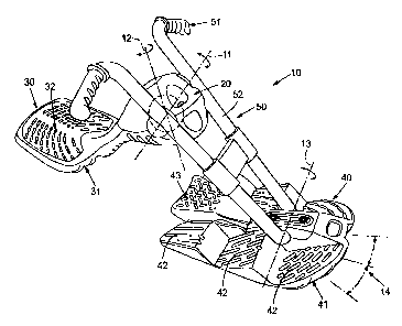
FIG. 1 is an isometric view of one embodiment of a snow sled showing relative
movement of the various components.
FIG. 2 is a side elevation of the snow sled of FIG. 1 sliowing a user seated
on the sled.
FIG. 3 is a cross-sectional view (along lines 3--3 of FIG. 1) showing how the
sled is
retractable from a riding configuration to a stowable configuration.
FIG. 3A is a detail view of FIG. 3 showing the foot section and the operation
of the
brake.
FIG 3B is a detail view of FIG. 3 showing the body section and handlebar
arrangement connection, and the relative movement of the handlebar arrangement
between
the riding configuration and the stowable configuration.
2

CA 02601404 2007-09-17
WO 2006/102165 PCT/US2006/009872
FIG. 4 is an exploded view of the body section and handlebar arrangement.
Detailed Description of the Preferred Embodiment
As shown in FIGS. 1 and 2, a snow sled 10 according to the present invention,
shown
in the riding configuration, includes a body section 20, a seat section 30, a
foot section 40,
and a handlebar arrangement 50. The seat section 30 is attached to the body
section 20 and
has an underside 31 for engaging the snow and a top side 32 for receiving a
seated rider 60.
The foot section 40 has an underside 41 for engaging the snow and is
positioned forward of
the seat section when the snow sled is deployed in the riding configuration.
The handlebar
arrangement 50 is connected to the body section 20 and to the foot section 40.
When seated
on the snow sled 10, the rider 60 grips the handlebar arrangeinent 50 at hand
grips 51 and
places his or her feet atop the foot section 40.
In the preferred embodiment, as indicated in FIG. 1, the top side 32 of the
seat section
30 includes raised ribs configured to grip the underside of the user 60. The
underside 31 of
the seat section 30 and the underside 41 of the foot section 40 include
channels configured to
direct the snow sled 10 in a generally forward direction.
The handlebar arrangement 50 is mounted to the body section 20 and pivotable
about
axis 11 and mounted to the foot section 40. The foot section 40 is pivotable
relative to the
handlebar arrangement 50 about axis 13. The relative movement between the
handlebar
arrangement 50 and both the body section 20 and the foot section 40 allows for
smooth
transition over bumps in the snow while the snow sled 10 is being ridden and
allows for a
retracted stowable configuration as indicated in FIG. 3. In the stowable
configuration the
foot section 40 nests underneath and adjacent the seat section 30, and the
handlebar
arrangement 50 is positioned adjacent the body section. The handlebar
arrangement 50 is
also pivotably moveable relative to the body section about axis 12, as
indicated in FIG. 1.
3

CA 02601404 2007-09-17
WO 2006/102165 PCT/US2006/009872
This movement allows the rider 60 to steer the snow sled 10, directing the
foot section 40 in
the directions indicated generally at 14.
The foot section 40 includes multiple foot engagement positions 42 and a
braking
member 43. As shown in FIGS. 3 and 3A, the braking member 43 of the foot
section 40
pivots about a connection 44. A spring 45 forces the braking member 43 in an
upward
direction preventing the bottom surface 46 of the braking member 43 from
engaging the snow
in a non-braking condition. The bottom surface 46 has a generally saw-tooth
shaped profile
configured to engage the snow when the rider 60 engages the top surface of the
braking
member 43 thus causing the spring 45 to compress and the bottom surface 46 to
extend below
the underside 41 of the foot section 40 in a braking condition. As shown in
FIG. 1, the top
surfaces of the braking member 43 and the foot engagement positions 42 include
raised ribs
configured to grip the underside of a rider's shoes.
As shown in FIG. 4, the handlebar arrangement 50 includes elongated sections
52
terminating in hand grips 51 at the upper end and terminating in a pivot
region 53 at the lower
end. The handlebar arrangement 50 also includes a joint member 54 located
generally
between the elongated sections 52. The joint member 54 is generally spherical
in shape and
is received by mating surfaces 21 of body section 20. The handlebar
arrangement 50 and
body section 20 connection is configured such that the handlebar arrangement
50 rotates
about an axis 11, indicated in FIG. 1, perpendicular to the snow sled
direction and passing
through the center of the joint member 54. The handlebar arrangement 50 also
rotates about
an axis 12, indicated in FIG. 1, and is described in more detail below.
Referring now to FIGS. 3B and 4, to facilitate the multiple degrees of freedom
of the
handlebar arrangement 50 and body section 20 connection described above, the
generally
spherical joint member 54 includes a channel 55 located approximately from the
plane
formed by the elongated sections 52 and continuing for approximately one
hundred degrees
4

CA 02601404 2007-09-17
WO 2006/102165 PCT/US2006/009872
clockwise, when viewed fioin the right-hand side of the snow sled 10, about
the generally
spherical joint member 54. Also, the mating surface 21 of the body section 20
includes a
cylindrical protrusion 22, the centerline of which fonns the axis 12,
indicated in FIG. 1, about
which the handlebar arrangement can rotate to facilitate steering. The channel
55 includes a
first channel section with a first width and a first depth and a second
channel section with a
second width less than the first width and a second depth greater than the
first depth, depth
being measured from the outer boundary of the generally spherical joint member
54, and
wherein the first and second channel sections share a bisecting plane. The
cylindrical
protrusion 22 includes a first cylindrical section with a diameter equal to or
slightly smaller
than the width of the first channel section and a second cylindrical section
with a diameter
equal to or slightly smaller than the width of the second channel section. The
first cylindrical
section is configured such that the first channel section slides and rotates
about the first
cylindrical section, and the second cylindrical section is configured such
that the second
channel section slides and rotates about the second cylindrical section.
As shown in FIG. 3B, a first end 56 of channel 55 abuts the cylindrical
protrusion 22
when the snow sled 10 is in the riding configuration. A second end 57 of
channel 55 abuts
the cylindrical protrusion 22 when the snow sled 10 is in the stowable
configuration.
While the invention has been disclosed in its preferred form, the specific
embodiment
thereof as disclosed and illustrated herein are not to be considered in a
limiting sense, as
numerous variations are possible. Applicant regards the subject matter of the
invention to
include all novel and non-obvious combinations and subcombinations of the
various
elements, features, functions and/or properties disclosed herein. No single
feature, function,
element or property is essential to all of the disclosed invention.
5

Representative Drawing
A single figure which represents the drawing illustrating the invention.
Administrative Status

2024-08-01:As part of the Next Generation Patents (NGP) transition, the Canadian Patents Database (CPD) now contains a more detailed Event History, which replicates the Event Log of our new back-office solution.

Please note that "Inactive:" events refers to events no longer in use in our new back-office solution.

For a clearer understanding of the status of the application/patent presented on this page, the site Disclaimer , as well as the definitions for Patent , Event History , Maintenance Fee  and Payment History  should be consulted.

Event History

Description Date
Application Not Reinstated by Deadline 2011-03-17
Time Limit for Reversal Expired 2011-03-17
Deemed Abandoned - Failure to Respond to Maintenance Fee Notice 2010-03-17
Inactive: Abandoned - No reply to s.30(2) Rules requisition 2010-03-01
Inactive: S.30(2) Rules - Examiner requisition 2009-09-01
Amendment Received - Voluntary Amendment 2009-06-15
Letter Sent 2008-08-18
Inactive: Single transfer 2008-05-13
Inactive: Cover page published 2007-12-07
Letter Sent 2007-12-05
Inactive: Acknowledgment of national entry - RFE 2007-12-05
Inactive: First IPC assigned 2007-10-18
Application Received - PCT 2007-10-17
National Entry Requirements Determined Compliant 2007-09-17
Request for Examination Requirements Determined Compliant 2007-09-17
All Requirements for Examination Determined Compliant 2007-09-17
Application Published (Open to Public Inspection) 2006-09-28

Abandonment History

Abandonment Date Reason Reinstatement Date
2010-03-17

Maintenance Fee

The last payment was received on 2009-03-04

Note : If the full payment has not been received on or before the date indicated, a further fee may be required which may be one of the following

  • the reinstatement fee;
  • the late payment fee; or
  • additional fee to reverse deemed expiry.

Patent fees are adjusted on the 1st of January every year. The amounts above are the current amounts if received by December 31 of the current year.
Please refer to the CIPO Patent Fees web page to see all current fee amounts.

Fee History

Fee Type Anniversary Year Due Date Paid Date
Request for examination - standard 2007-09-17
Basic national fee - standard 2007-09-17
MF (application, 2nd anniv.) - standard 02 2008-03-17 2008-02-22
Registration of a document 2008-05-13
MF (application, 3rd anniv.) - standard 03 2009-03-17 2009-03-04
Owners on Record

Note: Records showing the ownership history in alphabetical order.

Current Owners on Record
WHAM-O, INC.
Past Owners on Record
DAVID J. FITZGERALD
Past Owners that do not appear in the "Owners on Record" listing will appear in other documentation within the application.
Documents

To view selected files, please enter reCAPTCHA code :


To view images, click a link in the Document Description column. To download the documents, select one or more checkboxes in the first column and then click the "Download Selected in PDF format (Zip Archive)" or the "Download Selected as Single PDF" button.

List of published and non-published patent-specific documents on the CPD .

If you have any difficulty accessing content, you can call the Client Service Centre at 1-866-997-1936 or send them an e-mail at CIPO Client Service Centre.


Document
Description 
Date
(yyyy-mm-dd) 
Number of pages   Size of Image (KB) 
Description 2007-09-16 5 262
Drawings 2007-09-16 6 146
Claims 2007-09-16 4 128
Abstract 2007-09-16 1 68
Representative drawing 2007-12-05 1 16
Acknowledgement of Request for Examination 2007-12-04 1 176
Reminder of maintenance fee due 2007-12-04 1 112
Notice of National Entry 2007-12-04 1 202
Courtesy - Certificate of registration (related document(s)) 2008-08-17 1 103
Courtesy - Abandonment Letter (Maintenance Fee) 2010-05-11 1 171
Courtesy - Abandonment Letter (R30(2)) 2010-05-24 1 164
Correspondence 2007-12-04 1 23
Fees 2008-02-21 1 34