Note: Descriptions are shown in the official language in which they were submitted.
CA 02601423 2007-09-17
WO 2006/102239 PCT/US2006/010047
1
FORMED INFLATABLE CELLULAR CUSHIONING ARTICLE
AND METHOD OF MAKING SAME
Field of the Invention
The invention pertains to cellular cushioning articles, especially air
cellular
cushioning articles suitable for packaging end use.
Backzround of the Invention
Air cellular cushioning articles suitable for packaging applications have been
in
commercial use for several decades. One of the products in widespread
commercial use
is BubbleWrap cellular cushioning, one embodiment of which is made using heat
and
vacuum to form spaced-apart air-filled cavities in a first film and thereafter
heat sealing a
flat "backing" second film to the flats between the cavities of the first
film, so that air is
entrapped in each of the formed cavities making up the individualized cells.
The
resulting air-cellular cushioning product comprises discrete closed bubbles.
If any one
bubble deflates, no other bubble necessarily deflates. One significant
disadvantage of
BubbleWrap cellular cushioning is that shipping costs are high per unit
weight of
product because the product density is low, i.e., the shipping of such
products is mostly
shipping air.
Although Bubble Wrap cellular cushioning products have not been significantly
displaced by inflatable flexible cushioning articles, in the past there have
been a number
of commercialized air-cellular cushioning products for packaging which have
been
designed to be inflated by the end user, i.e., inflated and sealed shut
immediately before
end use by the packager. These products offer the advantage of being shippable
before
inflation, providing for much more efficient transport and storage before use,
as any given
volume within a truck or warehouse can hold over thirty times as much product
(on a
weight basis) if it is uninflated rather than shipped to the packager while
inflated.
Flat films which are sealed together to make an inflatable cellular cushioning
product exhibit a disadvantage of widthwise contraction upon inflation. One
way to
reduce widthwise contraction upon inflation is to thermoform one of the films
as
disclosed in U.S. Patent No. 6,423,166, to Simhaee. However, this product
exhibits the
disadvantage of having to remove entrapped air from the volume between the
bubble
CA 02601423 2007-09-17
WO 2006/102239 PCT/US2006/010047
2
sheet and the base layer, in order to achieve a higher density product which
provides the
advantage of more efficient transport and storage.
It would be advantageous to provide a cellular cushioning article having the
density advantage of an uninflated, inflatable product without having to
remove air from
within the cells. The removal of air is a process step which is time-consuming
and
difficult to carry out, especially to the degree of substantially complete
removal, or
complete removal, of the air from between the two films.
Summaa of the Invention
The present invention pertains to an inflatable flexible cellular cushioning
article
made from two films sealed together in a pattern providing a plurality of
inflatable
chambers. At least some of the chambers (preferably all of the chambers)
include a
plurality of inflatable cells connected to one another by connecting channels.
Both of the
films have formed regions which allow the article to undergo inflation with
reduced
lateral contraction relative to the inflation of unformed films which have
been sealed
together to make an inflatable cellular cushioning article. Because the formed
regions of
the second film are nested into the formed regions of the first film, both
films are formed
and there is no need to remove air from between the films in order to reduce
the volume
occupied by the formed inflatable article. Upon inflation of the article, the
formed
regions of the second film invert and separate from the formed regions of the
first film.
Relative to an unformed inflatable article, the formed regions impart
increased cell height
and increased cell volume, relative to an inflatable article made from
unformed films.
As a first aspect, the present invention is directed to an inflatable cellular
cushioning article comprising a first film bonded to a second film so as to
provide
between the first film and the second film a plurality of inflatable chambers.
Each of the
inflatable chambers comprises a plurality of cells. Each of the cells of the
same chamber
(i.e., of any given chamber) is connected to at least one adjacent cell by an
inflatable
connecting channel. The first film is,bonded to the second film between
adjacent
inflatable chambers. The first film and the second film each have at least one
formed
region corresponding with a location of a cell, with the at least one formed
region of the
second film being nested into the at least one formed region of the first
film. Optionally,
the regions of the films which are to serve as the connecting channels can
also be formed.
CA 02601423 2007-09-17
WO 2006/102239 PCT/US2006/010047
3
Preferably, the first film and the second film each have a plurality of formed
regions, each of the formed regions corresponding with the location of a cell,
with each of
the formed regions of the second film being nested into each of the formed
regions of the
first film.
Preferably, each of the formed regions of the first and second films is
surrounded
by an unformed, unbonded region of the film for enveloping a single inflatable
cell. This
unbonded region is preferably narrow, i.e., is from 0.2 mm to 6 mm, more
preferably
fromlmmto3nun.
Preferably, the inflatable chambers extend transversely across the inflatable
article. That is, the inflatable chambers extend in a direction which is
either
perpendicular to the machine direction of the inflatable article, or is within
45 degrees of
a line which is transverse to the machine direction of the inflatable article.
The first film can be bonded to the second film with an adhesive, a cohesive,
or a
heat seal. If an adhesive is used instead of heat sealing, an ultraviolet-
curable adhesive is
a preferred adhesive for bonding the first film to the second film.
In one preferred embodiment, the film(s) each have a unit weight of from 20 to
70
grams per square meter, and each of the formed regions in the film(s) each
have a
maximum dimension of from 0.25 to 3 inches. In another preferred embodiment,
the
film(s) each have a unit weight of from 60 to 250 grams per square meter, and
each of the
formed regions in the first film and the second film have a maximum dimension
of from
0.5 to 6 inches.
Preferably, each of the formed regions of the film(s) have a height of from
about 1
millimeter to about 50 millimeters. As used herein, the phrase "height of the
formed
region" refers to the maximum deviation of any one formed region from the
plane of the
unformed portion of the film, i.e., the plane containing the land area of the
film. Of
course, different formed regions can have different heights. More preferably,
the formed
regions of the film have a height of from 2 to 25 millimeters, more preferably
from 5 to
15 millimeters.
Preferably, each of the film(s) have a thickness of from about 0.5 to about 6
mils;
more preferably, from 1 to 3 mils.
In one embodiment of the present invention, the inflatable article has an open
inflation skirt along a first edge running the length of the inflatable
article.
CA 02601423 2007-09-17
WO 2006/102239 PCT/US2006/010047
4
In another embodiment, the inflatable article has a closed inflation manifold
running the length of the inflatable article. In a first species of this
alternative
embodiment, the closed inflation manifold extends along a first side edge
extending the
length of the inflatable article, with the plurality of inflatable chambers
extending from
the inflation manifold across the inflatable article and towards the other
side edge
extending the length of the inflatable article. In a second species of this
alternative
embodiment, a plurality of inflatable chambers extends from a first side of
the inflation
manifold and a plurality of inflatable chambers extends from a second side of
the inflation
manifold, with the inflatable chambers which extend from the first side of the
inflation
manifold extending across the inflatable article towards the first side edge
of the
inflatable article, and the inflatable chambers which extend from the second
side of the
inflation manifold extending across the inflatable article towards the second
side edge of
the inflatable article. In this second species, the closed inflation manifold
is not located
along one side edge of the article, but instead extends down an interior
portion of the
article. In one embodiment, the inflation manifold is centered on a
longitudinal (i.e.,
machine direction) centerline of the article.
Preferably, each of the inflatable chambers contains from 1 to 100 cells, more
preferably 2 to 50 cells, 3 to 20 cells, or 4 to 10 cells.
In one embodiment, the first and second films are connected to one another
along
one fold line. In another embodiment the first and second films are connected
to one
another along two fold lines. In another embodiment, the first film and second
film are
separate films. In another embodiment, the bond is a heat seal.
The first film and/or the second film can be a monolayer film or a multilayer
film.
Preferably the first film and/or the second film comprises at least one member
selected
from the group consisting of polyethylene, ethylene/alpha-olefin copolymer,
ethylene/unsaturated ester copolymer, ethylene/unsaturated acid copolymer,
polypropylene, propylene/ethylene copolymer, polyethylene terephthalate,
polyamide,
polyvinylidene chloride, polyacrylonitrile, ethylene/vinyl alcohol (i.e.,
EVOH, which is
actually the saponified ester of ethylene/vinyl acetate copolymer), and
propylene/vinyl
alcohol (i.e., PVOH). Preferably, the first film is a multilayer film and the
second film is
a multilayer film.
CA 02601423 2007-09-17
WO 2006/102239 PCT/US2006/010047
Preferably, the first film comprises a seal layer and an 02-barrier layer, and
the
second film comprises a seal layer and an 02-barrier layer. While the first
film and/or the
second film may further comprise a tie layer between the seal layer and the 02-
barrier
layer, the polymer which serves to tie the seal layer to the 02-barrier layer
may
5 alternatively be blended into either the 02-barrier layer or the seal layer,
in order to avoid
providing the film with a separate seal layer. However, it is'preferred that
the first film
and the second film each comprise the seal layer, the Oa-barrier layer, and a
tie layer
between the seal layer and the 02-barrier layer, with the seal layer of the
first film being
bonded to the seal layer of the second film in the inflatable article. The
seal layer of the
first and second films comprises at least one member selected from the group
consisting
homogeneous ethylene/alpha-olefin copolymer, very low density polyethylene,
low
density polyethylene, linear low density polyethylene, ethylene/unsaturated
acid
copolymer (particularly ethylene/vinyl acteate copolymer),
ethylene/unsaturated ester
copolymer, and ionomer resin. -
Preferably, the first film comprises first and second outer layers, a central
gas
barrier layer, a first tie layer between the first outer layer and the gas
barrier layer, and a
second tie layer between the gas barrier layer and the second outer layer.
Preferably, the
second film comprises first and second outer layers, a central gas barrier
layer, a first tie
layer between the first outer layer and the gas barrier layer, and a second
tie layer
between the gas barrier layer and the second outer layer. Preferably, the
first outer layer
of the first film is sealed to the first outer layer of the second film.
Preferably, the first
and second outer layers of the first film have the same layer thickness and
have the same
polymeric composition, and the first and second tie layers of the first film
have the same
layer thickness and the same polymeric composition, and the first and second
outer layers
of the second film have the same layer thickness and have the same polymeric
composition, and the first and second tie layers of the second film have the
same layer
thickness and the same polymeric composition. Preferably, the gas barrier
layer of the
first and/or second films comprises at least one member selected from the
group
consisting of polyamide, hydrolyzed ethylene/vinyl acetate copolymer,
polyvinylidene
chloride, polyacrylonitrile, and polyester, and the gas barrier layer of the
second film
comprises at least one member selected from the group consisting of polyamide,
CA 02601423 2007-09-17
WO 2006/102239 PCT/US2006/010047
6
hydrolyzed ethylene/vinyl acetate copolymer, polyvinylidene chloride,
polyacrylonitrile,
and polyester.
As a second aspect, the present invention is directed to a process for making
an
inflatable article, comprising: (A) bonding a portion of a first film to a
corresponding
5, portion of a second film so that a resulting sealed article comprises a
plurality of
inflatable chambers comprising a plurality of inflatable cells, each of the
cells in the
chambers being connected to an adjacent cell by an inflatable connecting
channel, the
first film being bonded to the second film between adjacent inflatable
chambers; and (B)
forming at least one region of the first film and at least one region of the
second film, the
formed regions corresponding with a location of a particular cell, with the
formed region
of the second film being nested into the formed region of the first film.
Optionally, the
process can further comprise extruding the first and second films and
thereafter cooling
the first and second films before bonding the first film to the second film.
Preferably, the process is an integrated process, in that the extrusion,
bonding, and
forming are carried out in an uninterrupted, continuous process. In a non-
integrated
process, an intermediate product is produced and placed aside awaiting further
processing
in one or more further processing steps. If an intermediate product is
maintained in the
production line, but is held in a moving inventory environment on a racking
system, with
the process being completed without separation of the film strand being
extruded, the
process is considered to be an integrated process.
Optionally, after the inflatable article is made, it can be pressed into a
flatter
configuration by a pressing means. That is, the formed regions of the article
can be
pressed into a configuration in closer alignment with the plane of the
unformed areas of
the article, so that upon winding the inflatable article into a roll, a wound
roll of greater
density can be produced. Means for pressing the article into the flatter
configuration
include nip rollers, oscillating flat plate press, etc.
In one embodiment, the first film and second film are extruded as separate
films,
either through separate slot dies or through separate annular dies. If through
separate
annular dies, the resulting film tubings can either be self welded in lay-flat
configuration
to form two flat films, or each can be slit lengthwise and bonded to one
another while
each is in its lay-flat configuration.
CA 02601423 2007-09-17
WO 2006/102239 PCT/US2006/010047
7
In another embodiment, the extrusion is carried out through a slot die, with
the
resulting film being folded to form the first and second films which are
connected to one
another along one fold line.
'In another embodiment, the extrusion is carried out through an annular die to
form
a tubular film which is collapsed into lay-flat configuration and slit
lengthwise to form the
first and second films which are connected to one another along one fold line.
In another embodiment, the extrusion is carried out through an annular die to
form
a tubular film which is collapsed into lay-flat configuration, to form first
and second films
which are connected to one another along two fold lines.
In one preferred embodiment, the bonding of the first film to the second film
is
carried out by passing the second film between a heat sealing roller and the
first film,
with both the first film and the second film making a partial wrap together
around the
sealing roller, with the second film making a longer partial wrap around the
sealing roller
than the first film, with the first film contacting the second film after the
second film has
made a portion of its partial wrap around the sealing roller. Preferably, the
process
further comprises contacting the first film with a nip roller while the first
and second
films are making the partial wrap together around the heat sealing roller, the
nip roller
pressing the first and second films together to assist in heat sealing the
first film to the
second film.
In one embodiment, the forming of the first and second films is carried out by
passing the first and second films together between: (i) an embossing roller
having a
plurality of cavities on the surface thereof; and (ii) a forming roller having
a plurality of
protuberances on the surface thereof. The forming roller has a surface
temperature low
enough to prevent the first and second films from fusing to one another in the
area being
formed. The protuberances on the forming roller are aligned to enter the
cavities of the
embossing roller between the embossing roller and the forming roller, with the
protuberances being undersized relative to the cavities of the embossing
rollers so that
portions of the first film which the protuberances force into the cavities in
the embossing
roller are not fused to the second film. Preferably, the forming roller and
the embossing
roller are in nip relationship with one another.
In one preferred embodiment, the embossing roller has an outer surface which
has
a temperature above ambient temperature. The temperature of the embossing
roller can
CA 02601423 2007-09-17
WO 2006/102239 PCT/US2006/010047
8
even be high enough to cause the first and second films to bond to one another
throughout
the land areas, i.e., the areas in which the first film or second film
contacts the embossing
roller. However, the process should not cause the first and second films to
bond to one
another in the area in which the first and/or second films are being formed.
Thus, the
temperature of the forming roller should be low enough that the first and
second films do
not bond to one another in the regions in which the first and/or second films
contact the
forming roller. In another preferred embodiment, the embossing roller has an
outer
surface at ambient temperature (i.e., room temperature), or below ambient
temperature,
with the forming being done "cold", i.e., without heating either of the films
to a
temperature at which bonding to one another occurs.
In one embodiment, the bonding step is carried out before the forming step. In
an
alternative embodiment, the forming step is carried out before the bonding
step. In yet
another embodiment, the bonding step and the forming step are carried out
simultaneously using a rotatable, heated sealing roller having an outer
surface, the outer
surface of the sealing roller comprising a first surface portion defining a
configuration
corresponding to a desired heat seal pattern and formed of a first material
having a first
thermal conductivity and a second surface portion formed of a second material
having a
second thermal conductivity lower, and preferably substantially lower, than
the first
thermal conductivity such that only areas of the film in contact with the
first surface
portion are heat sealed together while areas of the film contacted by the
second surface
portion remain unsealed to each other. Such a sealing roller is described in
U.S. Serial
No. (10/980,754), filed November 3, 2004, in the name of Robert O'Dowd,
entitled
"PROCESS AND APPARATUS FOR MAKING HEAT-SEALED ARTICLES", the
entirety of which is hereby incorporated by reference thereto.
In one embodiment, both the first and second films are formed in a plurality
of
regions, each of the regions corresponding with at least two adjacent cells of
the same
chamber, and at least one connecting channel connecting the two adjacent
cells.
Preferably, the formed region is continuous throughout the inflatable chamber,
and the
unformed region is continuous throughout the unformed region (i.e., land
area). With
this arrangement of formed and unformed regions, a smooth heat sealing roller
can
thereafter be used to heat seal the two films together in the unformed regions
between the
inflatable chambers.
CA 02601423 2007-09-17
WO 2006/102239 PCT/US2006/010047
9
Brie Description of the DNawin~s
FIG. 1 is an exploded perspective cut-away view of an inflatable article in
accordance with the present invention, before inflation.
FIG. 1 A illustrates a top view of the inflatable article of FIG. 1, except
that the
inflatable article is not exploded in the top view of FIG. 1A.
FIG. 2 is a cross-sectional view taken through section 2-2 of FIG. 1, except
that
the cross-sectional view is of the inflatable article unexploded.
FIG. 3 is an exploded perspective cut-away view of the inflatable article of
FIG. 1,
1 o after inflation.
FIG. 4 is a cross-sectional view taken through section 4-4 of FIG. 3, except
that
this cross-sectional view is of the inflatable article unexploded.
FIG. 5 is a perspective cut-away view of a first alternative inflatable
article in
accordance with the present invention, after inflation.
FIG. 6 is a perspective cut-away view of a second alternative inflatable
article in
accordance with the present invention, after inflation.
FIG. 7 is a schematic of a first process for making the inflatable article in
accordance with the present invention.
FIG. 8 is a schematic of an alternative process for making the inflatable
article in
accordance with the present invention.
Detailed Description of the Invention
As used herein, the term "film" is used in a generic sense to include plastic
web,
regardless of whether it is film or sheet. Preferably, films of and used in
the present
invention have a thickness of 0.25 mm or less.
As used herein, the phrases "first film" and "second film" include not just a
first
film which is discrete from (i.e., separated from) a second film, but also a
first film which
is a first leaf of a folded film (e.g., a centerfolded film) with the second
film being the
second leaf of the folded film. Still further, the first film could be a first
lay-flat side of a
lay-flat film tubing, and the second film could be a second lay-flat side of
the same film
tubing, with both lay-flat sides being joined to each other along two fold
lines.
CA 02601423 2007-09-17
WO 2006/102239 PCT/US2006/010047
As used herein, the phrase "flat film" is used with respect to a film which is
in the
form of a sheet, i.e., has side edges which form the film boundaries along its
length. A
flat film is to be contrasted with an annular film, which in lay flat position
has no side
"edges", but rather has side folds (which optionally may be creased) along the
length of
5 the film tubing.
As used herein, the phrase "inflatable chamber" refers to a contiguous volume
between two films bonded together to form an uninflated, inflatable article.
The
inflatable article of the present invention has a plurality of inflatable
chambers. While the
two films are preferably bonded to one another throughout the area between
adjacent
10 chambers, it is only necessary to bond the two films together along the
perimeter of the
inflatable chamber, so that upon sealing off the inflation channel after the
chamber has
been inflated, the inflation gas is retained within the chamber. The volume
within the
chamber is increased by introduction of inflation gas, which causes the two
films to
separate from one another to form an inflated chamber. Each inflated chamber
preferably
comprises a plurality of inflatable cells and a plurality of channels,
including an inflation
channel and at least one connecting channel. The phrase "inflatable cell", as
used herein,
refers to an enlarged region of an inflatable chamber. The phrase "inflation
channel"
refers to an inflatable passageway in a region of the inflatable article
through which the
inflation fluid can be pumped to fill an inflatable chamber. The phrase
"connecting
channel" refers to an inflatable passageway in a region of an inflatable
chamber through
which the inflation fluid can be pumped from one cell to another.
Because the inflatable article has inflatable chambers designed for use as
cellular
cushioning, each chamber is to be inflated with a gas. Air is the preferred
gas for
inflation. Other suitable gases include nitrogen, carbon dioxide, argon, and
helium, as
well as mixtures of these gases.
As used herein, the phrase "formed region" refers to a region of a film which
extends out of the plane of the film. For example, each of the "bubbles" in
the
thermoformed film portion of Bubble Wrap cellular cushioning is a formed
region.
Forming is a process in which the shape of the film is changed to a desired
configuration,
usually with the aid of heat and pressure to produce a non-elastic deformation
of the film,
thereby increasing the surface area of the film and the shape of the film.
However, as
used herein, the "forming" of a film, and the resulting "formed regions" in
the film,
CA 02601423 2007-09-17
WO 2006/102239 PCT/US2006/010047
11
include molding and casting processes, and the resulting articles,
respectively.
Preferably, the formed article of the present invention is made by
thermoforming or cold
forming of two flexible film sheets which have been bonded to one another
before
forming, or which are bonded to one another after the forming process is
carried out.
The phrase "maximum dimension", as used with respect to formed regions of
films, refers to the largest measured dimension of the formed region taken in
any of the
following: (a) the main plane of the film, and (b) in any plane parallel to
the main plane
of the film, and (c) any plane perpendicular to the main plane of the film.
As used herein, the term "nested" refers to the relationship in which at least
a
portion of the formed region of a second film resides within at least a
portion of a cavity
of the formed region of a first film. Nesting is present if any portion of the
formed region
of the second film breaks the plane across the base of the formed region of
the first film.
Nesting is maximized if the second film contacts the first film throughout the
cavity of
the first film.
As used herein, the phrase "a formed region corresponding with a location of a
cell" is inclusive of (a) formed regions limited to a single cell, e.g., a
formed film portion
which is surrounded by an unfonned, unbonded film portion of a single cell, as
well as (b)
formed regions which extend to or even through one or more boundaries between
one or
more unbonded portions of the film and one or more bonded portions of the
films. Thus,
any given formed region can include part or all of that portion of the films
which
envelops one or more cells of one or more inflatable chambers. Preferably,
however, the
inflatable article includes a plurality of formed regions, with each formed
region being
confined to an unbonded portion corresponding with a single cell.
As used herein, the term "seal" refers to any seal of a first region of a film
surface to
a second region of a film surface. The first and second regions can be on the
same or
different films. The seal is preferably formed by the use of heat and
pressure. In making the
seal, at least one region (preferably both regions) is heated to its seal
initiation temperature.
The sealing can be performed by any one or more of a wide variety of manners.
Peferably
sealing is carried out by contacting the films with a heated drum to produce a
heat seal, as
described below. The term "seal" is also inclusive of a film adhered to itself
with an
adhesive or cohesive, or films adhered to one another with an adhesive or
cohesive.
However, the various layers of a multilayer coextruded film are not considered
to be
CA 02601423 2007-09-17
WO 2006/102239 PCT/US2006/010047
12
"sealed" to one another because the term "seal", as used herein, refers to
adhering less than
the entire film surfaces to one another. Thus, a seal leaves an unsealed
region of the film.
In contrast, the bond holding coextruded entire film layers to one another is
herein
termed a"laminatlon". The term "lamination" is inclusive of not only layers
coming
together as molten streams, but also layers which are bonded to one another
with an adhesive
or cohesive.
The term "bond" is generic with respect to all manners of causing two films to
cleave to one another, i.e., to adhere firmly to one another. Bonding is
inclusive of being
adhered to one another with adhesive, corona treatment, heat sealing, etc.
Preferably, the
two films are bonded by being heat sealed to one another.
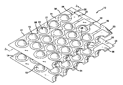
Referring to FIG. 1, FIG. 1A, and FIG. 2 together, there is shown an
inflatable
article 10 that has not yet been inflated. Inflatable article 10 has formed
regions 16 in
first film 12 and formed regions 18 in second film 14. Films 12 and 14 are not
bonded to
one another in formed regions 16 and 18. Formed regions 18 in second film 14
are nested
within the respective cavities of formed regions 16 of first film 12.
First film 12 and second film 14 are sealed together in bonded region 21. The
edges of bonded region 21 are shaped, sized, and located to define each of the
inflatable
chambers of inflatable article 10 as well as the inflation fluid entrance
ports 22 and
inflation channels 26. The entire shaded region in FIG. 1A corresponds with
the bonded
region 21 between first film 12 and second film 14.
Each of the inflatable chambers of inflatable article 10 includes inflatable
inflation
channel 26, a plurality of inflatable cells 24, and a plurality of inflatable
connecting
channels 28. The regions of films 12 and 14 which make up inflation channels
26 and
connecting channels 28 may be flat, i.e., unformed, as illustrated in FIG.s 1,
lA, and 2, or
may be formed and nested with one another, i.e., in a manner not illustrated
but
corresponding with the nesting of formed regions 16 and 18. Inflation channels
26
extend from open skirt 30 formed by unbonded film side edge regions 32 and 34.
Bonded region 21 between adjacent inflatable chambers are actually one
continuous sealed region, as bonded region 21 extends continuously along the
length of
longitudinal edge 35. See FIG. 1A. The portions of bonded region 21 which are
between
adjacent inflatable chambers, in combination with that portion of bonded
region 21 along
longitudinal edge 35, define the boundaries of each inflatable chamber. As can
be seen
CA 02601423 2007-09-17
WO 2006/102239 PCT/US2006/010047
13
in FIGs. 1 and 1A, bonded region 21 has a repeating pattern. Bonded region 21
is
preferably made using heat and pressure to cause a bond between the inner
surfaces of
films 12 and 14. Alternatively, films 12 and 14 may be adhesively bonded to
each other.
FIG. 3 is an exploded perspective cutaway view of inflated article 11 with
each
inflatable chamber heat sealed closed with heat seal 38. Heat seal 38 extends
along the
length of inflated article 11, providing a seal across each of inflation
channels 26.
Unbonded side edge regions 32 and 34 serve as flanges and together form open
skirt 30
used by the inflation apparatus (not illustrated) during the inflation
process. Inflated cells
24, inflated connecting channels 28, and those portions of inflated inflation
channels 26
which are downstream (relative to the flow of the inflation gas) of heat seal
38, together
become a single inflated chamber, with the resulting inflated cells 24 being
connected in
series and in fluid communication with one another, by inflated connecting
channels 28.
In each inflated chamber, inflated cells 24 are illustrated arranged in
series, with
inflated cells 24 of a chamber extending from proximate inflated cell 40,
i.e., the first cell
in the series, which is the cell closest to inflation channel 26, to distal
inflated cell 41,
which is the terminal cell in each inflated chamber. Each chamber has a
predetermined
length, with the length of each chamber being the same or different. As
illustrated in the
embodiments of FIG. 1 and FIG. 3, the length of adjacent chambers alternates
in an "A-
B-A-B..." arrangement, with each of the "A" chambers having the same length
and each
of the "B" chambers having the same length. Moreover, inflatable cells 24 in
adjacent
chambers are staggered, i.e., off-set from one another, in order that the
cells in adjacent
chambers are in a close-packed arrangement. The close-packing provides more
cushioning volume per unit area of inflatable article 10.
During inflation of each inflatable chamber, the formed region of second film
14
inverts and separates from the formed region of first film 12. That this
occurs can be seen
by comparing FIG. 1 with FIG. 3, as these two figures illustrate,
respectively, the same
inflatable article 10 before inflation (i.e., FIG. 1) and after inflation
(i.e., FIG. 3). The
inflation process forms an interior volume which expands upon the ingress of
inflation
gas into the inflatable chambers.
The depth to which films 12 and 14 are formed may represent virtually the
entire
thickness of the inflated cells, or may represent only a fraction of the
thickness of the
resulting inflated cells if both formed films bulge out to maximize the amount
of inflation
CA 02601423 2007-09-17
WO 2006/102239 PCT/US2006/010047
14
fluid between films 12 and 14 from inflation of the chamber. The latter is
illustrated in
the cross-sectional view of FIG. 4. Preferably, first film 12 and second film
14 are each
formed to a depth of from about 1 to about 50 millimeters, more preferably
from about 2
to about 25 millimeters, and more preferably from about 5 to about 15
millimeters. As
illustrated in the particular embodiment of FIG. 4, upon inflation the formed
regions of
second film 14 invert and the resulting inflated chambers bulge from the
inflation fluid,
resulting in a maximum thickness which is greater than twice the formed depth
of first
film 12 and second film 14.
The inner unbonded surfaces of side edge regions 32 and 34 can be brought into
close slidable engagement with outwardly facing surfaces of an appropriately
configured
nozzle or other inflation means so as to provide a partially-closed inflation
zone which
promotes efficient and reliable sequential inflation of the inflatable
chambers, without
restricting the movement of the web or inflation nozzle that is required to
effect this
sequential inflation. Unbonded side edge regions 32 and 34, which together
form the
open skirt, are preferably at least % inch to 3 inches in width and, more
preferably, from
1/2 inch to 1'/Z inches in width. Unbonded side edge regions 32 and 34 may
have different
widths; alternatively, they may have the same width, as in the embodiment
illustrated in
FIG. 1. A preferred apparatus and method for effecting inflation and sealing
of the
chambers is disclosed in USSN 10/057,067, Pub. No. 2002/0166788A1, published
Nov.
14, 2002, to Sperry et. al., entitled "APPARATUS AND METHOD FOR FORMING
INFLATED CHAMBERS", which is hereby incorporated, in its entirety, by
reference
thereto.
Once inflatable article 10 is inflated, inflated connecting channels 28 serve
as
flexible junctions, allowing the inflated article 11 to be readily bent so it
can be
conformed about a product, providing optimal cushioning. In another
embodiment, the
seal pattern can comprise relatively narrow seals that do not provide planar
regions. These
seals serve as the common boundary between adjacent chambers. Such a seal
pattern is
shown for example in U.S. Patent No. 4,551,379, the disclosure of which is
incorporated
herein by reference.
FIG. 5 is a perspective cut-away view of alternative inflated article 50 in
accordance with the present invention. Inflated article 50 is the same as
inflated article 11
illustrated in FIG. 3, except that instead of having the unbonded edge regions
32 and 34
CA 02601423 2007-09-17
WO 2006/102239 PCT/US2006/010047
which form an open skirt as in the embodiment of FIG. 3, inflated article 50
has
longitudinal sea137 running the length of the edge along inflation channels
22, forming
inflation manifold 52 which provides a closed channel for inflation of the
inflatable
chambers.
5 FIG. 6 is a perspective cut-away view of a second alternative inflated
article 54 in
accordance with the present invention. The embodiment of FIG. 6 differs from
the
embodiment of FIG. 5 in that it has an internally-located inflation manifold
56 having
inflatable chambers extending from opposing sides of inflation manifold 56.
Although
article 54 is illustrated as inflated, it would be provided with a
longitudinal seal (not
10 illustrated) along each side of inflation manifold 56, to seal each of the
inflated chambers
closed.
FIG. 7 is a schematic of a process for making the inflatable article of the
present
invention. In FIG. 7, extruders 62 and 64 extrude first flat film 120 through
a first slot
die, and second flat film 140 through a second slot die, respectively. After
extrusion, film
15 120 makes a partial wrap around heat transfer (cooling) roller 66, which
preferably has a
diameter of 8 inches and which is maintained at a surface temperature well
beneath the
fusion temperature of the extrudate, e.g., from 100-150 F. Second film 140
makes partial
wraps around each of heat transfer (cooling) rollers 68 and 70, each of which
has a
diameter of 8 inches and each of which is maintained at a surface temperature
similar to
that of cooling roller 66. After cooling, first film 120 makes a partial wrap
(about 90
degrees) around Teflon coated rubber nip roll 72, which has a diameter of 8
inches and
which has, as its primary function, maintaining nip with heat transfer
(heating) raised
surface roll 76. While first film 120 is making a partial wrap around nip roll
72, second
film 140 merges with first film 120, with films 120 and 140 being together in
partial wrap
for a short distance around nip rol172 before together entering first nip 74.
Nip roller 72
provides a location for films 120 and 140 to come together without being
marred or
distorted.
Thereafter, second film 140 makes direct contact with raised surface roller 76
(which is illustrated as a smooth roll only for simplicity of illustration).
First nip 74
subjects films 120 and 140 to a pressure of from 2 to 10 pounds per linear
inch, preferably
2 to 6 pounds per linear inch, more preferably about 4 pounds per linear inch.
CA 02601423 2007-09-17
WO 2006/102239 PCT/US2006/010047
16
Films 120 and 140 together contact raised surface roller 76 for a distance of
about
180 degrees. Raised surface roller 76 has a diameter of 12 inches, and is
heated by
circulating hot oil therethrough so that the roller surface is maintained at a
temperature of
from 280 F to 350 F. The edges of the raised surface on roller 76 are
rounded over to a
radius of 1/64 inch. Raised surface roller 76 also has a Teflon
polytetrafluoroethylene
coating thereon, with the raised surfaces being above the background by a
distance of 1/4
inch (0.64 cm). Moreover, the raised surface is provided with a surface
roughness of
from 50 to 500 root mean square (i.e., "rms"), preferably 100 to 300 rms, more
preferably
about 250 rms. This degree of roughness improves the release qualities of
raised surface
roller 76, enabling faster process speeds and a high quality product which is
undamaged
by licking back on raised surface roller 76.
The raised surface heats that portion of film 140 which contacts the raised
surface
of roller 76. Heat is transferred from raised surface roller 76, through a
heated portion of
film 140, to heat a corresponding portion of film 120 to be bonded to film 140
to produce,
for example, bonded region 21 of inflatable article 10 illustrated in FIG. 1.
Upon passing
about 180 degrees around raised surface roller 76, heated films 120 and 140
together pass
through second nip 78, which subjects heated films 120 and 140 to about the
same
pressure as is exerted in first nip 74, resulting in a bonded region between
films 120 and
140. The bonded region has a repeating pattern.
After passing through second nip 78, films 120 and 140, now bonded together,
pass about 90 degrees around heat transfer (cooling) roller 80, which has a
diameter of 12
inches and which has cooling water passing therethrough, the cooling water
having a
temperature of from 100 F to 150 F. Cooling roller 80 has a 1/ inch thick
(about 0.64
cm thick) release and heat-transfer coating thereon. The coating is made from
a
composition designated "SA-B4", which is provided and applied to a metal
roller by
Silicone Products and Technologies Inc of Lancaster, N.Y. The coating contains
silicone
rubber to provide cooling roller 74 with a Shore A hardness of from 40 to 100,
preferably
50-80, more preferably 50-70, and still more preferably about 60. The SA-B4
composition also contains one or more fillers to increase the heat
conductivity to improve
the ability of cooling roller 80 to cool the bonded region of the films.
Various additional
details of the apparatus and process of FIG. 7 are set forth in U.S. Patent
No. 6,800,162
B2 to Kannankeril et al., entitled INTEGRATED PROCESS FOR MAKING
CA 02601423 2007-09-17
WO 2006/102239 PCT/US2006/010047
17
INFLATABLE ARTICLE, issued October 5, 2004, which is hereby incorporated, in
its
entirety, by reference thereto. Inflatable article 100 thereafter passes
through a fonning
apparatus 84 (illustrated schematically in FIG. 7), which uses pressure alone,
or a
combination of heat and pressure, to form a plurality of locations on
inflatable article 100,
to result in uninflated, inflatable article 10 as illustrated in FIG. 1. Of
course, forming
apparatus 84 should not heat the unbonded regions of inflatable article 100 to
a
temperature high enough that the unbonded regions fuse to one another.
As an alternative to the process illustrated in FIG. 7, described above, the
film for
the entire article may be formed by extruding a single flat film (i.e.,
instead of two films
12 and 14) from a slot die having at least twice the desired width of the
inflatable article,
this film being center folded and bonded to itself to form the inflatable
article. As is
readily apparent, depending upon the manner in which the centerfolded film is
bonded
together, the resulting inflatable article can utilize an open inflation skirt
or a closed
inflation manifold.
Alternatively, a tubular film can be extruded through a single annular die, in
a
process producing a film having a circumference equal to twice the desired
width of the
inflatable article. In one embodiment, this tubular film is placed in lay flat
configuration
without any longitudinal slitting, with the inside of the tubing being bonded
to itself to
result in an inflatable article having a closed inflation manifold.
Alternatively, the tubular
film can be slit lengthwise, centerfolded in lay-flat configuration, and
bonded to itself to
form the inflatable article. Again, depending upon the manner in which the
bonding is
performed, the resulting inflatable article can have either an open inflation
skirt or a
closed inflation manifold.
FIG. 8 is a schematic of an alternative process for making an inflatable
article in
accordance with the present invention. FIG. 8 illustrates a process in which
flat films 121
and 141 are extruded from respective extruders 63 and 65, each of which have a
slot die
therewith, following which films 121 and 141 each make a partial wrap around
heat
transfer (cooling) rollers 67 and 69, respectively. Flat films 121 and 141 are
forwarded
off of respective cooling rollers 67 and 69 and come together on merging and
alignment
roller 73, with merged films 121 and 141 passing through a nip between
embossing roller
75 and forming roller 85.
CA 02601423 2007-09-17
WO 2006/102239 PCT/US2006/010047
18
Embossing roller 75 has a plurality of cavities 77 on the surface thereof
corresponding with the location of each of the cells of the inflatable
chambers, as well as
elongate-shaped cavities (not illustrated) corresponding to connecting
channels and
inflation channels, and circumferential channel 79 (optional) corresponding
with the
location of the inflation manifold (optional). Forming roller 85 has a
plurality of annular-
shaped protuberances 87 corresponding with the location of each of the cells
of the
inflatable chambers, as well as an elongate-shaped protuberances (not
illustrated)
corresponding to the connecting channels and inflation channels, and
circumferential
protuberance 89 corresponding with the location of the optional inflation
manifold.
Embossing roller 75 and forming roller 85 work together to form films 121 and
141 as
they pass through nip 83. Embossing roller 75 and forming roller 85 use
pressure and/or
vacuum, preferably in combination with heat, to form films 121 and 141.
Regions of film 121 are formed so that they nest within the cavities formed in
film
141. If heat is used in the forming operation, the temperature to which films
121 and 142
are heated should be below the temperature at which films 121 and 141 fuse
together
under the applied pressure in the nip. The forming which occurs in nip 83
transforms flat
films 121 and 141 so that they emerge from nip 83 as first formed film 123 and
second
formed film 143.
Of course, protuberances 87 and 89 on forming roller 85 are sized, positioned,
and
aligned to enter cavities 77 and 79 on embossing roller 75, in nip 83 between
embossing
roller 75 and forming roller 85. Protuberances 87 and 89 are undersized
relative to
cavities 77 and 79 on embossing roller 75. In the forming process, flat films
121 and 141
are formed, but not damaged, as they pass together through nip 83, at which
protuberances 87 and 89 force regions of films 121 and 141 into cavities 77
and 79, with
pressure alone or with a combination of heat and pressure. Heat can be
supplied by
heating at least the film-contact surface of embossing roller 75 and/or
forming roller 85.
In order to assist in the forming process, any heating which is used should
heat the films
to a temperature below which films 121 and 141 bond to one another, but above
the glass
transition temperature ("Tg") of one or more of the polymers in one or more of
films 121
and 141. Apparatus for heating films 121 and 141 to an elevated temperature is
not
illustrated in FIG. 8.
CA 02601423 2007-09-17
WO 2006/102239 PCT/US2006/010047
19
After emerging from nip 83, the resulting formed films 123 and 143 make a
partial wrap together around heat sealing roller 95. Formed films 121 and 141
contact
heat sealing roller 95 so that only the unformed area (i.e., "land area") of
formed film 121
is in direct contact with the hot surface of heat sealing roller 95. As
illustrated in FIG. 8,
the formed regions of formed films 123 and 143 are oriented away from heat
sealing
roller 95, so that the formed areas are not bonded to one another. The tension
on formed
films 123 and 143 presses the land areas of formed films 121 and 141 against
each other,
and together with the heat from heat sealing roller 95 for the period of the
partial wrap
around hot sealing roller 95, causes formed films 121 and 141 to be heat
sealed to one
1o another at the land area (i.e., the unformed area), while leaving the
formed areas unsealed
to one another, to result in an uninflated formed inflatable article, such as
inflatable article
illustrated in FIG. 1.
As an additional (and optional) step in the process illustrated in FIG. 6,
uninflated
formed inflatable article 10 can be run through an additional nip to mash the
formed
region of the films flat. This assists in winding up uninflated formed
inflatable article 11,
in that the formed areas, once flattened, are less destabilizing to the roll
than if the
inflatable article 10 is wound up in its formed but unflattened state.
Although embossing roller 75 as illustrated has cavities 77 which extend
inwardly
from a smooth cylindrical surface, embossing roller 75 could be provided with
multiple
flat surfaces each extending across roller 75, with cavities 77 extending
inwardly from a
given flat surface. For example, roller could have a hexagonal cross-sectional
shape with
each of the six cavities 77 being positioned in the middle of a side of the
hexagon.
Likewise, forming roller 85 could have a hexagonal cross-sectional shape with
each of the
six protrusions 87 extending from the middle of a side of the hexagon.
Providing such a
"faceted" design to the embossing and forming devices could be used in the
process of
FIG. 8, as well as in the process of FIG. 7, i.e., substituting for forming
apparatus 84.
Each roller could be provide with from 3-100 facets, more preferably from 6 to
50 facets,
more preferably from 12 to 50 facets, and more preferably from 20 to 50
facets.
A significant difference between the process of FIG. 7 and the process of FIG.
8 is
that in the process of FIG. 7, the inflatable article is made by first heat
sealing the films to
one another, and thereafter forming the films. In contrast, in the process of
FIG. 8, the
films are first formed and thereafter heat sealed to one another.
CA 02601423 2007-09-17
WO 2006/102239 PCT/US2006/010047
Further details concerning methods making inflatable article 10 are disclosed
below and are also disclosed in U.S. Patent No. 6,800,162 B2. Still further
details are
disclosed in several additional copending U.S. patent applications, including
(i) USSN
10/302004, entitled "HIGH STRENGTH HIGH GAS BARRIER CELLULAR
5 CUSHIONING ARTICLE", to Kannankeril et al., filed November 22, 2002,
published as
2004/0101658 Al, (ii) USSN 10/648113 entitled "HIGH STRENGTH HIGH GAS
BARRIER CELLULAR CUSHIONING ARTICLE", to Kannankeril et al., filed August
26, 2003, published as 2004/0101659 Al, and (iii) USSN 10/648,015, entitled
"PROCESS FOR MAKING AND AGING HIGH STRENGTH HIGH GAS BARRIER
1o CELLULAR CUSHIONING ARTICLE", to Kannankeril et al., filed August 26, 2003,
published as 2004/0099986A1. The entirety of each of these published
applications is
hereby incorporated by reference thereto.
The forming process utilized in FIG. 7 and FIG. 8 can be supplemented by
providing vacuum within the embossing roller 75 or 76. Vacuum can be supplied
as
15 described in, for example, U.S. Patent No. 2,776,451, to Chavannes,
entitled "Apparatus
and Method for Producing Embossed Thermoplastic Material", issued January 8,
1957,
which is hereby incorporated, in its entirety, by reference thereto. See also
U.S. Patent
No. 3,285,793, also to Chavannes, entitled "Method of Manufacturing a
Composite
Cellular Material", issued 15 November 1966, which is also hereby
incorporated, in its
20 entirety, by reference thereto. See also U.S. Patent No. 3,346,438, also to
Chavannes,
entitled "Method and Apparatus for Making Cushioning and Insulating Material",
issued
October 10, 1967, which is also hereby incorporated, in its entirety, by
reference thereto.
A preferred multilayer film structure for the film or films to be bonded
together to
make the inflatable cushioning article a symmetrical A/B/C/B/A layer
arrangement
having a total thickness of 1.5 mils. The A layers together make up 86 percent
of the total
thickness (each layer having a thickness of 43%, as preferably the layer
thickness is also
symmetrical), each of the B layers making up 2% of the total thickness, and
the C layer
making up 10% of the total thickness. Each of the A layers are made from a
blend of
45% by weight HCX002 linear low density polyethylene having a density of 0.941
g/cc
and a melt index of 4, obtained from Mobil, 45% by weight LF10218 low density
polyethylene having a density of 0.918 g/cc and a melt index of 2, obtained
from Nova,
and 10% by weight SLX9103 metallocene-catalyzed ethylene/alpha-olefin
copolymer,
CA 02601423 2007-09-17
WO 2006/102239 PCT/US2006/010047
21
obtained from Exxon. Each of the B layers are tie layers made of 100% Plexar
PX3236
anhydride modified linear low density polyethylene copolymer from Equistar
Chemicals
LP, of Houston, Texas. The C layer is an 02-barrier layer of 100% Caplon B
100WP
polyamide 6 having a viscosity of Far,=100, obtained from Allied Chemical.
Upon inflation, the cushioning article resists popping when pressure is
applied to a
localized area because connecting channels 28 allow air to move from one cell
into
another. The laminates show excellent creep resistance and cushioning
properties due to
inter-passage of air between cells.
Preferably, the film(s) are as thin as possible, in order to minimize the
amount of
resin used, but with the films being thick enough to provide adequate
durability.
Preferably, the film(s) have a total thickness of from about 0.1 to about 20
mils. More
preferably, each film has a total thickness from about 0.5 to about 10 mils,
more
preferably from about 0.8 to about 4 mils, and even more preferably from about
1.0 to
about 3 mils. Of course, the thickness may be somewhat reduced in the formed
regions.
The degree of thickness reduction depends upon the amount and manner in which
the
films are formed.
A dome-shaped formed region is a preferred shape for the film regions which
are
formed. The dome shape is preferred for the inflatable article illustrated in
FIGs. 1-6, and
in the inflatable article made in accordance with the processes illustrated in
FIG. 7 and
FIG. 8, each of which is described above. Preferred species of domed shapes
include
semi-sphere and oval section dome. Other preferred formed shapes include
vertically-
oriented cylinder with a flat top, vertically-oriented cylinder with a domed
top, conic-
shaped side walls with flat top or domed top, rectangular, cubic, horizontally-
oriented
cylinder section, and horizontally-oriented oval cross-section cylinder
section, as well as
wavy cylinder sections.
Of course, in the inflatable article made according to the process of FIG. 8,
the
films are also formed in the regions corresponding with the locations of the
connecting
channels, the inflation channels, and the open skirt or closed inflation
manifold. A
preferred shape for the film regions which correspond with the formed
connecting
channels and formed inflation manifold is a semi-cylinder shape in which the
cylinder is
halved in a plane including the central axis of the cylinder, with the
cylinder being on its
side, i.e., the axis of the cylinder being parallel to the lay-flat plane of
the film. The open
CA 02601423 2007-09-17
WO 2006/102239 PCT/US2006/010047
22
skirt can be formed in any manner which keeps the skirt away from the heat
sealing roller
during the heat sealing step as illustrated in FIG. 8. Of course, if the
process used to
make the inflatable article is a process as illustrated in FIG. 7, the film
regions which
correspond with the inflation manifold or open skirt need not be formed, as
the locations
of the raised surfaces of the raised surface roller (rather than the location
of the unformed
area) determine the locations which are heat sealed together. I
If desired, various additives are also included with the films. For example,
additives comprise pigments, colorants, fillers, antioxidants, flame
retardants, anti-
bacterial agents, anti-static agents, stabilizers, fragrances, odor masking
agents, anti-
blocking agents, slip agents, and the like. Thus, the present invention
encompasses
employing suitable film constituents.
Although the inflatable article is made by sealing two outer film layers to
one
another, if the film cross-section is symmetrical with respect to layer
composition, as is
preferred, both outer layers are herein referred to as "seal layers", even
though only one of
the layers is not heat sealed to the other film making up the inflatable
article. If the seal
layers make up the majority of the overall film weight, the seal layers are
present for more
purposes than just sealing. The seal layers can provide much of the strength,
bulk, abuse,
abrasion, and impact strength properties for the inflatable article.
Preferably the cross
section of the multilayer film is symmetrical with respect to layer
arrangement, layer
thickness, and layer composition.
Providing the film(s) with a gas barrier layer results in an inflated
cushioning
product having a longer life under load, as the gas barrier layer allows the
inflated
cushioning article to retain gas in the cells for a longer period of time
while the cells are
under load. This is important because without a gas barrier layer, the
cushioning product
under load can exhibit substantial loss of fluid, i.e., "creep", in, for
example, four to seven
days. Suitable resins for use in the gas barrier layer include hydrolyzed
ethylene/vinyl
acetate copolymer (designated by the abbreviations "EVOH" and "HEVA", and also
referred to as "ethylene/vinyl alcohol copolymer", and "saponified
ethylene/vinyl acetate
copolymer"), polyvinylidene chloride (including vinylidene chloride/vinyl
chloride
copolymer "PVDC-VC", and vinylidene chloride/methyl acrylate copolymer "PVDC-
MA"), polyacrylonitrile, polyester (including polyalkylene carbonate),
polyamide, etc., as
known to those of skill in the art. A particularly preferred gas barrier layer
is made from
CA 02601423 2007-09-17
WO 2006/102239 PCT/US2006/010047
23
100% CAPLON B100WP polyamide 6 having a viscosity of Fav = 100, obtained from
Allied Chemical.
If the film(s) are multilayer films having one or more seal layers and a
barrier
layer, it is likely that the polymer of the seal layer(s) does not bond
strongly to the polymer
of the barrier layer. The solution to this problem is to provide the film with
a tie layer
between each seal layer and the barrier layer. As used herein, the phrase "tie
layer" refers to
any internal layer having the primary purpose of adhering two layers to one
another. A tie
layer contains a polymer capable of covalent bonding to polar polymers such as
polyamide
and ethylene/vinyl alcohol copolymer, as well as being able to bond to, for
example,
polyolefins such a polyethylene and ethylene/alpha-olefin copolymers. A tie
layer can serve
to provide a strong bond to both the seal layer and the gas barrier layer. The
tie layer can
comprise any polymer having a polar group thereon (particularly a carbonyl
group), or
any other polymer which provides sufficient interlayer adhesion to adjacent
layers which
comprise polymers which do not adequately adhere to one another. Such polymers
include olefin/unsaturated ester copolymer, olefin/unsaturated acid copolymer,
and
anhydride modified olefin polymers and copolymers, e.g., in which the
anhydride is
grafted onto the olefin polymer or copolymer. More particularly, polymers for
use in tie
layers include anhydride modified polyolefin, anhydride modified
ethylene/alpha-olefin
copolymer, ethylene/vinyl acetate copolymer, ethylene/butylacrylate copolymer,
ethylene/methyl methacrylate copolymer, ethylene/acrylic acid copolymer,
ethylene/methacrylic acid copolymer, and polyurethane. Modified polymers
suitable for
use as tie layers are described in U.S. Patent No. 3,873,643, to Wu et al,
entitled "Graft
Copolyiners of Polyolefins and Cyclic acid and acid anhydride monomers"; U.S.
Patent
No. 4,087,587, to Shida, et al, entitled "Adhesive Blends'.'; and U.S. Patent
No.
4,394,485, to Adur, entitled "Four Component Adhesive Blends and Composite
Structures", each of which are hereby incorporated, in their entirety, by
reference thereto.
Preferred polymers for use in the tie layer include olefin polymers which are
modified (e.g., grafted) with one or more monomers such as acrylic acid,
methacrylic
acid, fumaric acid, maleic acid, maleic anhydride, 4-methyl cyclohex-4-ene-1,2-
dicarboxylic acid anhydride, bicyclo(2.2.2)oct-5-ene-2,3-dicarboxylic acid
anhydride,
1,2,3,4,5,8,9,10-octahydronaphthalene-2,3-dicarboxylic acid anhydride, 2-oxa-
1,3-
diketospiro(4.4)non-7-ene, bicyclo(2.2.1)hept-5-ene-2,3-dicarboxylic acid
anhydride,
CA 02601423 2007-09-17
WO 2006/102239 PCT/US2006/010047
24
maleopimaric acid, tetrahydrophthalic anhydride, x-methylbicyclo(2.2.1)hept-5-
ene-2,3-
dicarboxylic acid anhydride, x-methylnorborn-5-ene-2,3-dicarboxylic acid
anhydride,
norborn-5-ene-2,3-dicarboxylic acid anhydride, Nadic anhydride, methyl Nadic
anhydride, Himic anhydride, methyl Himic anhydride and other fused ring
monomers, as
known to those of skill in the art.
In the inflatable cellular cushioning article of the present invention, the
tie layer
can provides a high level of adhesive and cohesive strength in order to
prevent the
multilayer film from delaminating when the article is inflated to an internal
pressure of 3
psi under standard conditions (i.e., 25 C and 1 atmosphere pressure), and
thereafter
subjected to harsh conditions, for example, 140 F for 4 hours. Not just any
tie layer
polymer is capable of providing a level of adhesive and cohesive strength
adequate to
provide the 3 psi inflated article with the desired performance properties
when subjected
to harsh conditions. More particularly, a tie layer made of 100 percent
anhydride grafted
low density polyethylene having an anhydride content of at least 160 parts per
million
based on resin weight (as measured by pyrolysis GC-MS), preferably about 190
parts per
million, exhibits a level of adhesive and/or cohesive strength to prevent the
article, when
inflated to 3 psi, from delaminating under harsh conditions. Preferably, the
modified
polyolefin is selected from modified LLDPE, modified LDPE, modified VLDPE, and
modified homogeneous ethylene/alpha-olefin copolymer.
Preferred polymers for use in the seal layer include homogeneous
ethylene/alpha-
olefin copolymer, heterogeneous ethylene/alpha-olefin copolymer (such as very
low
density polyethylene and linear low density polyethylene), ethylene
homopolymer (low
density polyethylene and high density polyethylene), ethylene unsaturated
ester
copolymer (e.g., ethylene vinyl acetate copolymer, ethylene butyl acrylate
copolymer,
etc), ionomer resin, and polyamide.
EXAMPLE
An inflatable article in accordance with the present invention was prepared in
a
manner similar to the process illustrated in FIG. 5, discussed above, with the
exception
that forming was not carried out in a fully integrated process as illustrated
in FIG. 5.
Rather, two flat films were extruded from two slot dies, respectively. Each
film was a
multilayer film having a thickness of 1.5 mils, each film having a symmetrical
CA 02601423 2007-09-17
WO 2006/102239 PCT/US2006/010047
A/B/C/B/A layer arrangement, symmetrical layer composition, and symmetrical
layer
thicknesses. Each of the films had a unit weight of 38 grams per square meter.
The layer
arrangements, thicknesses, and compositions were as follows:
5 Table I
Thickness of
Layer Each Layer (% Layer Composition
Identity of Total Film
Thickness
A Blend of 45 wt % HCX002 linear low density
Seal Layer 43 polyethylene, 45 wt. % LF102181ow density
polyethylene, and 10% by weight SLX9103
metallocene-catalyzed ethylene/alpha-olefin
copolymer
B 2 100 wt. Percent Plexar PX3236 anhydride
Tie layer modified linear low density polyethylene
copolymer
C 10 100% Caplon B 100WP polyamide 6
Barrier Layer
The flat films were cooled and thereafter heat sealed together by being passed
in
partial wrap around a raised surface roller in the manner illustrated by FIG.
5. The raised
surface roller heat sealed the two films together in a pattern providing 7
cells connected in
10 series by 6 connecting channels (i.e., one connecting channel between each
pair of
adjacent cells) having a width of about 9/16 inch and a length of about 3/16
inch. Each of
the cells had a diameter of about 13/ inches. An inflation channel having a
length of
about % inch and a width of about 9/16 inch connected the open skirt to the
proximate
cell. The open skirt was formed by flaps of film each having a width of 7/8
inch. Each
15 cell was circular in shape and had a diameter of about 1.75 inches.
A 3'/a-inch long piece of the resulting uninflated, unformed, inflatable
article 100
was cut from the roll, the piece extending across the full 151/2 inch width of
the inflatable
CA 02601423 2007-09-17
WO 2006/102239 PCT/US2006/010047
26
article. The 3'/a-inch long piece of the inflatable article had one chamber
running down
the middle thereof.
Each of the 7 cell regions was individually heated, i.e., one at a time, for
about 5
seconds with air at 240 F, using a from a Steinel HG 3002 LCD heat gun,
obtained from
Steinel America, Inc., 9051 Lyndale Avenue South, Bloomington, MN 55423.
Immediately after the heating of each of the cell regions, the resulting hot
portion of the
article was placed in the press portion of a Mullen Tester, obtained from B.R.
Perkins &
Son, Inc., of Holyoke, MA. The press portion of the Mullen tester was used to
press the
hot portion of both of the films to form a dome-shaped region having a
diameter of one
inch and a height of approximately 3/8 inch. Both films were formed
simultaneously
without trapping air between the films, and without any fusion of the films in
the formed
areas. Each of the 7 cell regions of the films was formed in this manner.
After each of the cell regions were formed as described above, the resulting
formed inflatable article 10 was inflated to an internal pressure of 3 psi,
and a heat seal
was made across the inflation channel to seal the chamber closed and entrap
the air, under
pressure, within the closed chamber. The inflated cells exhibited a total
thickness of
about 1 inch.
A measurement across the width of the formed, inflated article revealed that
the
width of the inflated article was about 13 3/8 inches, i.e., a width reduction
upon inflation
of from 15 '/2 inches to 13 3/8 inches, which was a width reduction of only
about 13.5
percent. A comparative sample of the unformed, uninflated inflatable chamber
10 was
inflated to about 3 psi. The comparative inflated chamber was sealed closed at
3 psi, and
when measured revealed a width reduction of from about 15 '/2 inches to 10 3/4
inches,
i.e., a width reduction upon inflation of about 31 percent.
Thus, in the inflatable article according to the invention, the reduction in
width
contraction upon inflation appeared to be due to the forming of the cell
regions of the
films. It is believed that if the forming is carried out throughout the entire
cell region, and
if both films are formed to a dome height of about'/2 inch, the width
reduction upon
inflation to a pressure of about 3 psi will be very low, i.e., close to 0
percent. Moreover,
the height of the inflated cells in the formed inflatable article 10 was about
25% higher
than the height of the cells in the inflated comparative sample.
~~~
CA 02601423 2007-09-17
WO 2006/102239 PCT/US2006/010047
27
In the figures and specification, there have been disclosed preferred
embodiments
of the invention. All sub-ranges of all ranges disclosed are included in the
invention and
are hereby expressly disclosed. Those slcilled in the art will appreciate that
numerous
changes and modifications may be made to the embodiments described herein, and
that
such changes and modifications may be made without departing from the spirit
of the
invention.