Note: Descriptions are shown in the official language in which they were submitted.
CA 02601510 2012-10-03
METHOD OF OPERATING A FLUID BED REACTOR
5
hcari rPentor.THIS INVENTION relates to a method of operating a fluid bed
reactor and to
Considerable risk is encountered when technology is scaled up from pilot
plant scale to commercial plant scale in order to reap the benefits of economy
of scale.
Fluid bed reactor's, such as three-phase slurry reactors and two-phase
fluidised bed
reactors, typically exhibit scale-dependent macro-mixing effects and the
aforementioned
risk is thus applicable when fluid bed reactors are scaled up. It will thus be
an
advantage if a method can be found which can significantly reduce the risk
associated
with upscaling of fluid bed reactors. In addition, reactor designs in which
the mixing
patterns inside the reactor can be more readily modelled or predicted from
experimentation have the benefit that the extent of usually undesirable back-
mixing can
be limited thereby potentially allowing an optimal combination of desirable
plug-flow
characteristics (usually good productivity and good selectivity) and well-
mixed
characteristics (often required for desirable solids distribution and even
temperature
profiles).
The applicant is aware of US 6,375,921, WO 99/00191, FR 160354 7 US
2,853,369 and GB 728543. US 6,375,921 discloses a three-phase slurry vessel
with
perforated trays with a substantially uniform distribution of holes, which can
be used for
counter-current operation. WO 99/00191 is concerned with methods for in-situ
regeneration of partially and reversibly deactivated catalysts used in bubble
column
reactors. This document proposes providing a reactor shell in which is placed
a draft
tube located coaxially within the reactor shell. FR 160354 7 deals with
problems
associated with growing yeast on an industrial scale, more particularly with
problems
regarding ensuring good contact of the yeast with oxidising gas and two
immiscible
liquid phases. FR 1603547 proposes a reactor defining a flow path having
intercalated
1
CA 02601510 2007-09-15
Printed: 28-06-2007 laGOL.117PlIVI ' 'PC-171B 2006/050 835,
2
concentrically arranged upflow and downflow channels. US 2,853,369 attempts to
address the problem of back-mixing by sub-dividing a reactor into a plurality
of
channels. GB 728543 is concerned with improving hydrocarbon synthesis in a
slurry
reactor. This document teaches the use of a tower-like reactor with cooling
being
performed in a number of vertically spaced stages in the reactor. None of
these
documents deals specifically with ways to reduce the risk encountered when
technology
is scaled up from pilot plant scale to commercial plant. scale, or proposes
reactor
designs in which the mixing patterns inside the reactor can be more readily
modelled or
predicted from experimentation.
According to one aspect of the invention, there is provided a method of
operating a two-phase fluidised bed reactor, the method including
feeding at a low level at least one gaseous reactant into a vertically
extending
fluidised body of solid particles, the fluidised body being contained in at
least two
vertically extending shafts housed within a Common reactor shell, each shaft
being
divided into a plurality of vertically extending channels at least some of
which are in flow
communication and the fluidised body being present in at least some of the
channels;
allowing the gaseous reactant to react as it passes upwardly through the
fluidised
body present in at least some of the channels of the shafts, thereby to form a
gaseous
product;
allowing gaseous product and/or unreacted gaseous reactant to disengage from
the fluidised body in a head space above the fluidised body; and
withdrawing gaseous product and unreacted gaseous reactant, if present, from
the
head space.
Typically, the withdrawn gaseous product and unreacted gaseous reactant
include solid particles from the fluidised body. The method may thus include
separating
the solid particles from the gases, e.g. by means of cyclones. The method may
also
include returning the separated solid particles to the fluidised body.
The method may include maintaining the fluidised body at a desirable level
by adding or removing solid particles, e.g. by means of pneumatic methods.
Preferably,
a tail gas is used in such pneumatic methods to fluidise the solid particles
if they are to
be added to the fluidised body.
2 AMENDED SHEET 12:-02-2007
= Printed: 28-06-2007
CA 026015102007-09-15 r/AIVILJ
:PCTA B 2006/060 836
3
The invention extends to a method of operating a three-phase slurry reactor
as hereinafter described. In describing the invention further, reference is
thus made to
a slurry body instead of a fluidised body. It is however to be appreciated
that what is
stated in respect of the invention with reference to a slurry body or slurry
is also
applicable to the invention with reference to a fluidised body of solid
particles, unless it
would clearly be understood not to be applicable by a person skilled in the
art of fluid
bed reactors.
Thus, according to another aspect of the invention, there is provided a
method of operating a three-phase slurry reactor, the method including
feeding at a low level at least one gaseous reactant into a vertically
extending
slurry body of solid particles suspended in a suspension liquid, the slurry
body being
contained in at least two vertically extending shafts housed within a common
reactor
shell, each shaft being divided into a plurality of vertically extending
channels at least
some of which are in slurry flow communication and the slurry body being
present in at
least some of the channels;
allowing the gaseous reactant to react as it passes upwardly through the
slurry
body present in at least some of the channels of the shafts, thereby to form a
non-
gaseous or a gaseous product;
allowing gaseous product, if present, and/or unreacted gaseous reactant to
disengage from the slurry body in a head space above the slurry body;
withdrawing gaseous product, if present, and/or unreacted gaseous reactant
from
the head space; and
if necessary, maintaining the slurry body at a desired level by withdrawing
suspension liquid, including non-gaseous product if present, or by adding
suspension
liquid.
The method may include passing a heat transfer medium through some of
the channels of the shafts, the heat transfer medium-containing channels of a
shaft
being in flow communication.
The channels of a shaft may be in parallel planes and may alternately contain
the slurry body and the heat transfer medium.
31
AMENDED SHEET
12-02-2007
Printed: 28-06-2007 CA 02601510 2007-09-15 P-CT/IB 2006/050 835
4
Instead, the method may include surrounding the channels of a shaft with
heat transfer medium. The channels may thus be in the form of vertically
extending
tubes, with the shafts being defined by vertically extending side walls
dividing the
reactor. The side walls may form chords of the shell when the shell is
circular cylindrical
and when seen in horizontal section.
Heat transfer surfaces of the reactor, such as those of the tubes and/or the
side walls, may optionally be shaped or textured to increase their heat
transfer surface
area or to improve heat transfer coefficients, compared to those of smooth
cylindrical
tubes or smooth side walls. The shaping or texturing may include, amongst
other
methods known to persons skilled in the art, the use of dimpled, ribbed or
finned tubes
or plates.
Slurry flow communication between channels in a shaft preferably only
occurs at top and/or bottom ends of such channels.
As will be appreciated, each shaft with its channels acts as a slurry bubble
reactor or three-phase slurry reactor (or in the case of a fluidised bed
reactor, as a two-
phase fluidised .bed reactor). Design and testing of a single shaft on a pilot
scale is
feasible, with a commercial scale reactor then including a plurality of the
shafts, thereby
substantially reducing the risk of scale-up.
While it is believed that the method according to the second aspect of the
invention can, at least in principle, have broader application, it is
envisaged that the
solid particles will normally be catalyst particles for catalysing the
reaction of the
gaseous reactant or gaseous reactants into a product, i.e. a liquid product
and/or a
gaseous product. The suspension liquid will normally, but not necessarily
always, be
= liquid product, with liquid phase thus being withdrawn from the slurry
body to maintain
the slurry body at a desired level.
Furthermore, while it is also believed that, in principle, the method
according
to the second aspect of the invention can have broader application, it is
envisaged that
it will have particular application in hydrocarbon synthesis where the gaseous
reactants
AMENDED SHEET 12-02-2607
CA 02601510 2007-09-15
Printed: 28-08-2007, .PCT/IB 2008/050 836
ummirkkivi
. ,
5
are capable of reacting catalytically exothermically in the slurry body to
form liquid
hydrocarbon product and, optionally, gaseous hydrocarbon product. In
particular, the
reaction or hydrocarbon synthesis may be Fischer-Tropsch synthesis, with the
gaseous
reactants being in the form of a synthesis gas stream comprising mainly carbon
monoxide and hydrogen, and with both liquid and gaseous hydrocarbon products
being
produced and the heat transfer medium being a cooling medium, e.g. boiler feed
water.
The method may include allowing slurry to pass downwardly from a high level
in the slurry body to a lower level thereof, using one or more channels in the
shafts.
This may include preventing gaseous reactant or reactants from entering one or
more
channels in the shafts, e.g. by providing a baffle, thereby allowing these
channels to act
as downcomers, and/or it may include degassing the slurry in the channel, e.g.
by
adding a degasser to an upper end of the channel.
The process may include cooling the gas from the head space to condense
liquid product, e.g. liquid hydrocarbons and reaction water, separating the
liquid product
from the gases to provide a tail gas, and recycling at least some of the tail
gas to the
slurry body as a recycle gas stream.
At least some individual shafts may each have a gaseous reactant inlet. The
method may include feeding the gaseous reactant or reactants, or recycle gas,
to these
individual shafts. The gaseous reactant or reactants may be fed independently
from the
feed to another shaft, particularly another shaft at the same elevation.
At least some of the shafts may each have a slurry or a suspension liquid
outlet or inlet. The method may include maintaining the slurry body level in
these shafts
by adding or withdrawing slurry or suspension liquid through the liquid inlet
or outlet.
The suspension liquid or slurry may be added to or withdrawn from a shaft
independently from another shaft, particularly another shaft at the same
elevation.
At least some of the shafts may each include or define a filtration zone for
the
removal of liquid phase from the reactor. The liquid phase may be withdrawn
from a
shaft independently from another shaft.
5-, AMENDED SHEET 12-02-2007
Printed: 28-06-2007
CA 02601510 2007-09-15i...a.71.ar MI VI l-f
Pc-ot3 2006/050 836
=
6
At least two of the vertically extending shafts may be vertically spaced, with
an upper end of a lower shaft being below a lower end of an upper shaft. The
method
may include allowing slurry to pass downwardly from a high level in the slurry
body in
the upper shaft to a lower level thereof, and the method may include allowing
slurry to
5 pass downwardly from a high level in the slurry body of
the lower shaft to a lower level
thereof. The method of the invention thus allows slurry redistribution or
recycle over
selected vertically extending regions of the reactor, which is less
detrimental to plug flow
behaviour than slurry recycle over the total reactor height. At the same time,
as a result
of the use of the channels, the desirable features of a high aspect ratio
(length/diameter
ratio) for the reactor are realised. However, if desired, the method may
include allowing
slurry to pass downwardly from a high level in the slurry body in the upper
shaft to a low
level in the slurry body in the lower shaft, e.g. by having channels which are
vertically in
register, or which are vertically connected to be in flow communication,
acting as
downcomers.
The method may include feeding recycle gas at an elevated level into the
slurry body, so that said recycle gas passes only through the upper shaft or
upper
shafts and bypasses the lower shaft or lower shafts.
The method may include preventing slurry flow communication between
adjacent shafts, or between all shafts at the same elevation. Instead, the
method may
allow slurry communication between adjacent shafts at an elevation between the
upper
ends and lower ends of the shafts, or the method may include allowing slurry
flow
communication between shafts at the lower ends of the shafts, particularly
between the
lower ends of lower shafts. The method may also include allowing slurry flow
communication between shafts in one vertical region, but preventing slurry
flow
communication in a different vertical region between the same shafts to hinder
the
establishment of macro-mixing patterns.
According to a further aspect of the invention, there is provided a two-phase
fluidised bed reactor, the reactor including
a reactor shell housing at least two vertically extending sub-reactors each
defining
a plurality of vertically extending channels at least some of which are in
flow
6
AMENDED SHEET
12-2-2007
Printed: 28-06-2007
CA 02601510 2007-09-15L.A./
PCT/IB 2006/050 836
7
communication and which define a fluidised bed zone which, in use, will
contain a
fluidised body of solid particles;
a gas inlet in the reactor shell for introducing a gaseous reactant or gaseous
reactants into the reactor; and
5 a gas outlet in the reactor shell
for withdrawing gas from a head space in the
reactor shell above one or more of the sub-reactors.
The fluidised bed reactor may include a solid particles inlet or outlet for
adding or withdrawing solid particles to or from the reactor.
According to yet another aspect of the invention, there is provided a three-
phase slurry reactor, the reactor including
a reactor shell housing at least two vertically extending sub-reactors each
defining
a plurality of vertically extending channels at least some of which are in
slurry flow
communication and which define a slurry zone which, in use, will contain a
slurry of
solid particles suspended in a suspension liquid;
a gas inlet in the reactor shell for introducing a gaseous reactant or gaseous
reactants into the reactor;'µ
a gas outlet in the reactor shell for withdrawing gas from a head space in the
reactor shell above one or more of the sub-reactors; and
if necessary, a liquid inlet or a liquid outlet .for adding or withdrawing
slurry or
suspension liquid to or from the reactor.
Typically, at least some of the sub-reactors of the slurry reactor include or
define a filtration zone for the removal of liquid phase from the reactor.
The sub-reactors may include a plurality of vertically extending divider walls
which between them define the vertically extending channels. One or more
vertically
extending side walls of a sub-reactor may be defined by a divider wall of one
or more
adjacent sub-reactors.
Typically, at least some of the channels are heat transfer medium flow
channels, having heat transfer surfaces.
7
AMENDED SHEET
12-02-
2007
Printed: 28-06-2007 CA 02601510 2007-09-15 PCT/ IB 2006/050 835
8
Instead, the sub-reactors may include a plurality of vertically extending
tubes,
each tube defining a channel. Vertically extending baffles or side walls may
define
sides of the sub-reactors. Two adjacent sub-reactors may share a common baffle
or
side wall. The side walls may be as hereinbefore described.
Typically, the tubes have a diameter of at least 10 cm.
Heat transfer surfaces of the reactor, such as those of the tubes and/or the
side walls, may optionally be shaped or textured to increase their heat
transfer surface
area or to improve heat transfer coefficients compared to those of smooth
cylindrical
tubes or smooth side walls. The shaping or texturing may include, amongst
other
methods known to persons skilled in the art, the use of dimpled, ribbed or
finned tubes
or plates.
When the sub-reactors include a plurality of vertically extending divider
walls
which between them define the vertically extending channels, at least some of
the
channels may be heat transfer medium flow channels. When the sub-reactors
include a
plurality of vertically extending tubes, a heat transfer medium flow space may
be
defined between the baffles or side walls of a sub-reactor, the heat transfer
medium
flow space thus surrounding the tubes.
Typically, the heat transfer medium flow channels or the heat transfer
medium flow space are/is in flow communication with a heat transfer medium
inlet
arrangement and a heat transfer medium outlet arrangement. The heat transfer
medium inlet arrangement and the heat transfer medium outlet arrangement may
serve
all of the heat transfer medium flow channels in a sub-reactor. The heat
transfer
medium inlet or outlet arrangement of one sub-reactor may be in flow
communication
respectively with the heat transfer medium inlet or outlet arrangement of
another sub-
reactor.
The heat transfer medium flow channels and the channels defining slurry or
fluidised bed zones may be arranged alternately.
The reactor may include one or more of the sub-reactors arranged at a lower
level in the shell and one or more sub-reactors arranged at a higher level in
the shell,
AMENDED SHEET 12-02-2007'
Printed: 28-06-2007 CA 02601510 2007-09-15 PCT/[B2006/O50 835
9
such that lower ends of channels of the upper sub-reactor(s) are above upper
ends of
the channels of the lower sub-reactor(s).
The reactor may include an intermediate zone between the upper sub-
reactor(s) and the lower sub-reactor(s). The intermediate zone may be in flow
communication with slurry or fluidised bed zone channels of an upper sub-
reactor or
upper sub-reactors and with slurry or fluidised bed zone channels of a lower
sub-reactor
or lower sub-reactors.
The gas inlet may be arranged to feed a gaseous reactant or gaseous
reactants directly into at least some of the sub-reactors, at low elevations
in the sub-
reactors. Typically, the gas inlet is arranged to feed a gaseous reactant or
gaseous
reactants directly into each of the lower sub-reactors, at low elevations in
these lower
sub-reactors.
The reactor may include a recycle gas inlet. The recycle gas inlet may be
arranged to feed recycle gas directly into at least some of the sub-reactors.
The recycle
gas inlet may be arranged to feed recycle gas directly into each of the lower
sub-
reactors and/or each of the upper sub-reactors. When being arranged to feed
recycle
gas directly to the upper sub-reactors, the recycle gas inlet may be arranged
to feed the
recycle gas into the intermediate zone.
One or more channels of a sub-reactor may be a downcomer channel. A
downcomer channel may be provided at its lower end with a gassing prevention
device,
e.g. a baffle, and/or it may be provided at its upper end with a degasser. A
downcomer
channel in an upper sub-reactor may be in register or in flow communication
with a
downcomer channel in a lower sub-reactor. instead, a downcomer channel in an
upper
sub-reactor may be horizontally spaced or staggered from a downcomer channel
in a
lower sub-reactor directly beneath the upper sub-reactor.
Preferably, each sub-reactor has a vertically extending side facing the shell
or being defined by the shell. This allows for piping arrangement to or from
each sub-
reactor.
9 AMENDED SHEET 12-02-2007
Printed: 28-06-2007 CA 02601510 2007-09-15 PCT/E3 2006/050 835
10
Adjacent sub-reactors at a particular elevation in the shell may be isolated
from one another as far as slurry or fluidised body flow communication is
concerned.
However, in one embodiment of the invention, slurry or fluidised body flow
communication between adjacent sub-reactors is provided for below the lower
sub-
reactors, i.e. in a bottom of the reactor. Also, in one embodiment of the
invention, slurry
or fluidised body flow communication is provided for between adjacent upper
sub-
reactors, below the upper sub-reactors but above the lower sub-reactors.
Typically, this
is achieved by allowing slurry or fluidised body flow between adjacent upper
sub-
reactors, in the intermediate zone.
Typically, where slurry or fluidised body flow communication between sub-
reactors at the same elevation has been allowed, slurry or fluidised body flow
communication is not allowed between sub-reactors that are in register with
the sub-
reactors between which slurry or fluidised body flow communication has been
allowed,
but which are located at another elevation.
Typically, slurry or fluidised body flow communication between upper ends of
adjacent upper sub-reactors is prevented. Thus, although the head space above
the
upper sub-reactors is common to the upper sub-reactors, slurry or fluidised
body is
typically prevented from flowing from the upper end of a channel of one sub-
reactor to
another adjacent sub-reactor, e.g. by means of side walls of the sub-reactors
extending
into the head space above a normal slurry or fluidised bed level in each upper
sub-
reactor.
The invention will now be described in more detail with reference to the
accompanying drawings, in which
Figure 1 shows schematically an elevational sectional view of a three-phase
slurry
reactor in accordance with the invention;
Figure 2 shows a sectional top plan view of the slurry reactor of Figure 1;
Figure 3 shows an elevational sectional view of another embodiment of a three-
phase slurry reactor in accordance with the invention; and
Figure 4 shows a sectional top plan view of the slurry reactor of Figure 3.
10 AMENDED SHEET 12-02-200'7'
CA 02601510 2007-09-15
Printed: 28-06-2007 taLok-fr POT/i2006/050 835
11
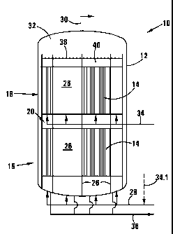
Referring to Figures 1 and 2 of the drawings, reference numeral 10 generally
indicates a three-phase slurry phase reactor in accordance with the invention.
The
reactor 10 is suitable for hydrocarbon synthesis in a process in which gaseous
reactants
in the form of a synthesis gas are reacted in a slurry body or slurry bed
comprising a
product suspension liquid and catalyst particles.
The reactor 10 includes a reactor shell 12 housing twenty-four
parallelipipedal sub-reactors 14. The sub-reactors 14 are grouped in groups of
twelve
each, with onc group generally indicated by reference numeral 16 being lower
sub-
reactors and another group, generally indicated by reference numeral 18 being
upper
sub-reactors. The upper sub-reactors are vertically spaced from the lower sub-
reactors
leaving an intermediate zone 20 between the upper sub-reactors 18 and the
lower sub-
reactors 16.
Each sub-reactor 14 includes a plurality of vertically extending metal divider
walls or plates 22 which between them define vertically extending channels 24.
The
sub-reactors 14 also have side walls 26. As can be clearly seen in Figure 2,
the side
walls 26 of some of the sub-reactors 14 are defined by a divider wall 22 of an
adjacent
sub-reactor 14, with the divider walls 22 of these two sub-reactors 14 being
perpendicularly arranged.
Although not shown in Figures 1 and 2, at least some of the divider walls or
plates 22 may be shaped or textured to increase their heat transfer surface
area or to
improve heat transfer coefficients. The shaping or texturing may include,
amongst other
methods known to persons skilled in the art, the use of dimpled, ribbed or
finned plates.
The reactor 10 also includes a gas inlet 28 at a low elevation, below the
lower sub-reactors 16 and a gas outlet 30 at a high elevation. The gas outlet
30 is in
flow communication with a head space 32 in the shell 12 above the upper sub-
reactors
18. A recycle gas inlet 34 leads into the intermediate zone 20 and a liquid or
slurry
outlet 36 leads from below the lower sub-reactors 16.
The channels 24 of each sub-reactor 14 are alternately slurry channels and
cooling channels. In other words, in use, the channels 24 of a sub-reactor 14
contain
either slurry, or boiler feed water as a heat transfer or cooling medium, with
the slurry
AMENDED SHEET 12-02-2007
Printed: 28-06-2007 CA 02601510 2007-09-15:PCTAB 2006/050 835:i
12
and boiler feed water being present in alternate channels. Each sub-reactor 14
is thus
provided with a heat transfer medium inlet arrangement (not shown) and a heat
transfer
medium outlet arrangement (not shown). The heat transfer medium inlet
arrangement
of a sub-reactor 14 in use feeds boiler feed water into all of the cooling
channels of the
sub-reactor 14, at one end thereof. The heat transfer medium outlet
arrangement
withdraws the boiler feed water from all of the cooling channels, at the other
end of the
sub-reactor 14. The flow of the boiler feed water through the cooling channels
may be
either up or down, i.e. co-current or counter-current in use to gaseous
reactants and
ycluu,LLS product bubbles !icing up through the slurry channels.
The slurry channels are open-ended. Unlike the slurry channels, the cooling
channels have closed upper and lower ends, but are in flow communication with
each
other at their ends and with the heat transfer medium inlet and outlet
arrangements, in a
construction reminiscent of a plate heat exchanger.
In the embodiment of the invention shown in Figures 1 and 2, the side walls
26 of the lower sub-reactors 16 extend downwardly to the shell 12 where they
are
sealed against the shell 12. In other words, below the channels 24 of the
lower sub-
reactors 16, the lower sub-reactors 16 are not in flow communication. The gas
inlet 28
thus feeds each of the lower sub-reactors 16 individually. Typically, a
gaseous reactant
flow controller (not shown) will be provided for each of the lower sub-
reactors 16.
Similarly, the liquid outlet 36 is arranged to withdraw liquid from below each
of the lower
sub-reactors 16 individually. Typically, a slurry body or slurry bed level
controller (not
shown) is associated with each of the upper sub-reactors 18, to control the
withdrawal
of liquid or slurry from the lower sub-reactors 16.
As can be seen in Figure 1 of the drawings, in the intermediate zone 20,
there is also no horizontal slurry flow communication between the lower sub-
reactors 16
or between the upper sub-reactors 18, by virtue of the side walls 26 of either
the upper
or lower sub-reactors 16, 18 forming barriers in the intermediate zone 20.
However, the
lower sub-reactors 16 are in slurry flow communication with the upper sub-
reactors 18
immediately above them. In other words, a sub-reactor 14 which is a lower sub-
reactor
and which is vertically in register with a sub-reactor 14 which is an upper
sub-reactor, is
in flow communication with the upper sub-reactor.
12 AMENDED SHEET 12-02-2007
CA 02601510 2012-10-03
13
The side walls 26 of the upper sub-reactors 18 extend upwardly into the head
space 32 to project upwardly above a normal slurry level indicated by
reference numeral
38. As a result, at their upper ends, the upper sub-reactors 18 are also not
in horizontal
slurry flow communication, although they share the common head space 32.
The recycle gas inlet 34 feeds each upper sub-reactor 18 individually as
shown schematically in Figure 1. If desired, a recycle gas flow controller can
be
provided for each of the upper sub-reactors 18. The arrangement of the recycle
gas
inlet 34 in Figure 1 is shown schematically only. In practice, as a result of
the fact that
each of the sub-reactors 14 typically has at least one side wall 26 facing the
shell 12, it
is typically easy to provide each of the upper sub-reactors 18 with an
individual recycle
gas inlet extending through the shell 12. Similarly, for the liquid outlet 36
and the gas
inlet 28, if it is not desired to enter through the bottom of the shell 12,
these piping
arrangements can enter through the circular cylindrical shell 12 as the lower
sub-
reactors 16 also each have at least one side wall 26 facing the shell 12.
At least some of the slurry channels 24 of the upper sub-reactors 18 and the
lower sub-reactors 16 are configured to function as downcomer channels. These
channels are provided at their lower ends with a gassing prevention device,
such as a
baffle (not shown), and/or at their upper ends with a degasser -(not shown). A
downcomer channel in an upper sub-reactor 18 may be located directly above or
may
be in register with a downcomer channel of a lower sub-reactor 16. If desired,
these
two downcomer channels may also physically be connected so that they are in
direct
flow communication with one another. Instead, a downcomer channel in an upper
sub-
reactor 18 may be horizontally spaced or staggered from a downcomer channel in
a
lower sub-reactor 16.
The reactor 10 is suitable for many processes requiring a three-phase slurry
reactor and requiring heat transfer to or from the slurry. However, only one
use, namely
hydrocarbon synthesis, will now be described.
In use, fresh synthesis gas comprising mainly carbon monoxide and
hydrogen as gaseous reactants, is fed into the bottom of the reactor 10
through the gas
13
Printed: 28-06-2007
CA 02601510 2007-09-15COL, ,
F'CT/IB 2006/050 835
.14
inlet 28. The synthesis gas is fed individually into each of the lower sub-
reactors 16 and
is typically uniformly distributed through a sparger system (not shown) inside
each of
the lower sub-reactors 16. Simultaneously, a recycle gas stream (typically
cooled)
comprising typically hydrogen, carbon monoxide, methane and carbon dioxide is
5 returned to the reactor 10 through the recycle gas inlet
34. All of the recycle gas stream
may be fed into the upper sub-reactors 18 by means of the recycle gas inlet 34
or, if
desired, a portion of the recycle gas stream may be returned to the bottom of
the
reactor 10 as shown by the line 34.1 entering the gas inlet 28.
As with the fresh synthesis gas, the recycle gas is fed to each of the upper
sub-reactors 18 individually and is typically uniformly distributed inside the
upper sub-
reactors 18 by means of a sparger system (not shown) inside each of the upper
sub-
reactors 18. By using the recycle gas inlet 34, it is thus possible to allow a
portion of the
recycle gas to bypass the slurry located in the lower sub-reactors 16. In this
fashion,
the overall gas hold-up in the reactor 10 can be reduced, thereby surprisingly
increasing
the reactor capacity.
The gaseous reactants, comprising the fresh synthesis gas and any recycle
gas, pass upwardly through a slurry body 40 which occupies the slurry channels
of the
upper and lower sub-reactors 18, 16 and which extends from the bottom of the
reactor
10 to the level 38. The slurry body 40 comprises Fischer-Tropsch catalyst
particles,
typically an iron- or cobalt-based catalyst, suspended in liquid product. The
slurry body
40 is controlled to have the slurry level 38 above the open upper ends of the
slurry
channels 24 of the upper sub-reactors 18 but below the upper ends of the side
walls 26
of the upper sub-reactors 18 which extend into the head space 32.
As the synthesis gas bubbles through the slurry body 40, the gaseous
reactants therein react catalytically and exothermically to form liquid
product, which thus
forms part of the slurry body 40. From time to time, or continuously, liquid
phase or
slurry comprising liquid product is withdrawn through the liquid outlet 36,
with the slurry
level 38 in each of the upper sub-reactors 18 thus being controlled
individually. The
catalyst particles are separated from the liquid product in a suitable
internal or external
separation system, e.g. using filters (not shown). If the separation system is
located
14
AMENDED SHEET
12-02-2007
Printed: 28-06-2007 CA 02601510 2007-09-15 PCT/IB 2006/050 835
15
externally to the reactor 10, an additional system (not shown) to return the
separated
catalyst particles to the reactor 10 is then provided.
The fresh synthesis feed gas and the recycle gas are introduced into the
reactor 10 at a rate sufficient to agitate and suspend all of the catalyst
particles inside
the reactor 10 without settling. The gas flow rate will be selected depending
on the
slurry concentration, catalyst density, suspending medium density and
viscosity, and
particular particle size used. Suitable gas flow rates include, for example,
from about 5
cm/s to about 50 cm/s. However, gas velocities up to about 85 cm/s have been
tested
in bubble columns. The use of higher velocities has the disadvantage that it
is
accompanied by a higher gas hold-up in the reactor leaving relatively less
space to
accommodate the catalyst-containing slurry. Whatever gas flow rate is however
selected, it should be sufficient to avoid particle settling and agglomeration
in the sub-
reactors 14.
Some slurry continuously passes downwardly through the downcomer
channels thereby to achieve redistribuiion of catalyst particles within the
slurry body 40
and to promote uniform heat redistribution throughout the slurry body 40. As
will be
appreciated, depending on the arrangement of the downcomer channels in the
upper
sub-reactors 18 and their associated lower sub-reactors 16, slurry
redistribution over
selected vertically extending regions of the reactor 10 is possible.
Each sub-reactor 14 is operated so that the slurry bed 40 therein is in a
heterogeneous or churn-turbulent flow regime and comprises a dilute phase
consisting
of fast-rising larger bubbles of gaseous reactants and gaseous product which
traverse
= 25 the slurry body 40 virtually in plug-flow fashion and a dense phase
which comprises
liquid product, solid catalyst particles and entrained smaller bubbles of
gaseous
reactants and gaseous product. By means of the use of the sub-reactors 14, the
plug-
flow behaviour of the entire reactor 10 is promoted, since each sub-reactor 14
has a
high aspect ratio well in excess of the aspect ratio of the shell 12.
The slurry body 40 is present in alternate, or open-ended, channels 24 in
each sub-reactor 14. Boiler feed water as cooling medium is circulated through
the
remaining, close-ended, channels 24 to remove the heat of the exothermic
reactions.
1;67- AMENDED SHEET 12-02-2007
CA 02601510 2007-09-15
Printed: 28-06-2007 1.1L...t.JV rlav PCT/IB 2006/050835.
16
As will be appreciated, the divider walls 22 provide large heat transfer
surface areas for
removing heat from the slurry body 40.
Light hydrocarbon products, such as a C20 and below fraction are withdrawn
from the reactor 10 through the gas outlet 30 and passed to a separation unit
(not
shown). Typically, the separation unit comprises a series of coolers and a
vapour-liquid
separator and may optionally include further coolers and separators and
possibly also a
cryogenic unit for removal of hydrogen, carbon monoxide, methane and carbon
dioxide
from the C20 and below hydrocarbon fraction. Other separation technologies
such as
10, membrane units, pressure swing adsorption units and/or units for the
selective removal
of carbon dioxide may be employed. The separated gases comprising nitrogen,
carbon
monoxide and other gases are compressed and recycled by means of a compressor
(not shown) to provide the recycle gas stream. Condensed liquid hydrocarbons
and
reaction water are withdrawn from the separation unit for further working up.
It is to be appreciated that, although the reactor 10, as illustrated, allows
for
the recycle of gas to the reactor 10, it is not necessarily so that a recycle
gas stream will
be employed in all embodiments.
In the embodiment of the invention shown in Figures 1 and 2, no slurry flow
communication is possible between sub-reactors 14 at the same elevation. It is
however quite easy to modify the reactor behaviour to obtain transverse or
horizontal
slurry flow communication at selected elevations inside the reactor 10. Thus,
for
example, by removing or modifying the portions of the side walls 26 of the
lower sub-
reactors 16 extending downwardly below the lower sub-reactors 16, it is
possible to
allow slurry flow communication between the lower sub-reactors 16 in the
bottom of the
reactor 10. In a similar fashion, slurry flow communication between the lower
sub-
reactors 16 or between the upper sub-reactors 18 can also be established in
the
intermediate zone 20.
Referring to Figures 3 and 4 of the drawings, another embodiment of a three-
phase slurry reactor in accordance with the invention is generally indicated
by reference
numeral 100. The reactor 100 embodies the same concepts as the reactor 10 and
thus
includes many parts or features that are the same or similar. These parts or
features
16 AMENDED SHEET 12-02-200/
Printed: 28-06-2007 CA 02601510 2007-09-15 PCT/IB 2006/050 835.
17
are indicated by the same reference numerals in Figures 3 and 4 as in Figures
1 and 2,
unless othenNise indicated.
In the reactor 100, the side walls 26 of each sub-reactor define chords of the
shell 12, as can be clearly seen in Figure 4. Instead of having divider walls
like the
divider walls 22 of the reactor 10, the reactor 100, in each of the sub-
reactors 14, has a
plurality of vertically extending tubes 102 arranged between upper and lower
tube plates
104. Between the side walls 26 and surrounding the tubes 102, a heat transfer
medium
flow space (boiler feed water flow space) 106 is defined.
The reactor 100 is operated in similar fashion to the reactor 10, with the
slurry body 40 occupying the tubes 102. In the embodiment shown in Figures 3
and 4,
as is the case with the reactor 10, there is no slurry flow communication
allowed,
between adjacent lower sub-reactors 16, in the bottom of the reactor 100, or
between
adjacent upper sub-reactors 18, above the upper sub-reactors 18 in the head
space 32.
However, in the intermediate zone 20, slurry flow communication between
adjacent sub-
reactors 14 is allowed.
Although not shown in Figures 3 and 4, at least some of the tubes 102 may
be shaped or textured to increase their heat transfer surface area or to
improve heat
transfer coefficients. The shaping or texturing may include, amongst other
methods
known to persons skilled in the art, the use of dimpled, ribbed or finned
tubes.
In use, boiler feed water is circulated through the boiler feed water flow
spaces 106, typically entering each sub-reactor 14 at a low elevation and
leaving at a
high elevation.
As with the reactor 10, each sub-reactor 14 of the reactor 100 can easily be
provided with piping arrangements as each sub-reactor 14 has a side wall
defined by
the shell 12.
It is believed that the reactors 10, 100, as illustrated, are of designs which
substantially reduce the risk of scaling up from pilot plant scale to
commercial plant
scale, exhibiting reduced scale dependent macro-mixing effects. It is also
believed that
these reactor designs can be more readily modelled or predicted from
experimentation
17; AMENDED SHEET 12-02-2007
Printed: 28-06-2007 CA 026015102007-09-15 PCT/1B 2006/050 835:
18
allowing better combinations of desirable plug flow characteristics and well-
mixed
characteristics of reactants and products. Design and testing of a single sub-
reactor on
a pilot scale is possible, with scale-up now merely involving adding sub-
reactors. The
illustrated reactor designs also provide for high heat transfer surface areas
and shared
services such as filtration over a serviceable sub-reactor. These designs also
allow for
vertically staged downcomers reducing the detrimental effect on plug flow
behaviour of
downcomers acting over the entire reactor height. Catalysts can also be
segregated
vertically to a greater extent than in prior art reactor designs of which the
Applicant is
aware. This can advantageously be used, specifically for iron catalysts, to
expose less
of the catalyst to areas in the reactor with high water partial pressure that
negatively
affect catalyst activity, leading to increased reactor productivity.
=
18 AMENDED SHEET 12-02-2007'