Note: Descriptions are shown in the official language in which they were submitted.
CA 02601944 2007-09-04
WO 2006/094189 PCT/US2006/007591
RETRACTABLE ELECTRIC CORD RECEIVING DEVICE AND
VENTILATION APPARATUS
BACKGROUND OF THE INVENTION
Field of the Invention
[0001] The present invention relates generally to retractable power
cords. More particularly, the invention relates to retractable power cords for
electrically powered devices.
Related Art
[0002] Conventionally, it is well known to incorporate retractable
power cords in electrically powered devices such as vacuum cleaners, and the
like.
However, in the case of vacuum cleaners, conventionally, retractable power
cord
mechanisms have been used with canister type vacuum cleaners because of the
large amount of space required to include a retractable cord. Handheld
vacuums,
e.g., thus have not conventionally included retractable power cords because
handhelds do not have the space to accommodate the length of cord needed for a
vacuum cleaner. Thus, some vacuum cleaners have conventionally included non-
retractable power cords, -or in t1he case of rechargeable vacuums have-l?a6r:c-
power cord in the vacuum unit. Unfortunately however, rechargeable vacuum
cleaners often can run out of charge at inopportune times, and may suffer from
less power, or require additional weight to accommodate batteries. Thus, it
would
be desirable to provide a handheld electrically powered device such as a
vacuum
cleaner that could accommodate a retractable cord of sufficient length to be
1
CA 02601944 2007-09-04
WO 2006/094189 PCT/US2006/007591
useful, while avoiding the need for the time to recharge and battery weight of
rechargeable models.
BRIEF SUMMARY OF THE INVENTION
[0003] An exemplary embodiment of the present invention includes a
cord winding mechanism for an electrically powered device such as a vacuum
cleaner. An exemplary embodiment of the present invention may include a cord
winding mechanism which may be used with an electrically powered component,
such as, e.g., but not limited to, an electric -motor.
[0004] The cord winding mechanism, in an exemplary embodiment,
may include a cord receiving member for receiving a cord. In one exemplary
embodiment, the cord receiving member may be a physical structure capable of
receiving a cord around, or within it to allow retracting of the power cord.
[0005] In one exemplary embodiment, the cord receiving member may
resemble a spool. In another exemplary embodiment, the cord receiving member
may resemble a reel.
[0006] In yet another exemplary embodiment, the cord receiving
member may include an edge portion and a plurality of cross members. In an
- exemplary embodiment, there may-be two edge -poF=:ions,-arid-the edge
portions
may include, e.g., a circular, rectangular, square, polygonal, or other shape.
In an
exemplary embodiment, the edge portion may have one or more openings. The
opening may be used for ventilation, or to receive a portion of the
electrically
powered component. In an exemplary embodiment, the plurality of cross
members may include, e.g., but not limited to, three (3), four (4), or more
cross
members. One or more of the plurality of cross members may be parallel, or not
2
CA 02601944 2007-09-04
WO 2006/094189 PCT/US2006/007591
parallel, in one exemplary embodiment. In another exemplary embodiment, the
cord receiving member may include a broad portion and a narrow portion for
receiving the cord. In one exemplary embodiment, the cord receiving member
may include a conical member. In one exemplary embodiment, the cord receiving
member may resemble two co-axial cones coupled point to point.
[0007] In one exemplary embodiment, the cord receiving member may
define an interior space inside the cord receiving member. In one exemplary
embodiment, the cord receiving member may have an axis. In one exemplary
embodiment, the cord receiving member may include a surface about which the
cord may be wound. In one exemplary embodiment, the surface may be an
outside surface. In one exemplary embodiment, the cord receiving member may
include an end surface to contain the cord as the cord is retracted. In one
exemplary embodiment, the cord may be received within the inside of the cord
receiving member. In another exemplary embodiment, the cord may be received
outside of the cord receiving member.
[0008] In one exemplary embodiment, the cord receiving member may
be adapted to be manually wound. In one exemplary embodiment, a crank may be
provided to allow manually rewinding the cord about the axis of the cord
receiving member. In an exemplary embodiment, the crank may be any of
integrated, removable, or collapsible.
[0009] In another exemplary embodiment, the cord receiving member
may be adapted to be automatically rewound. In one exemplary embodiment, the
cord winding mechanism may further include a biasing member that may transmit
a rotational force to the cord receiving member to rotate the cord receiving
member about the axis.
3
CA 02601944 2007-09-04
WO 2006/094189 PCT/US2006/007591
[00010] In an exemplary embodiment, the cord winding mechanism
may further include a retention member. In one exemplary embodiment, the
retention member may be adapted to selectively prevent the cord receiving
member frorn rotating under the rotational force of the biasing member.
[00011] In one exemplary embodiment, the cord receiving member may
be adapted to receive at least part of the electrically powered component such
as,
e.g., but not limited to, a motor, or electrical 'motor, inside the interior
space of the
cord receiving member.
[00012] In one exemplary embodiment, the cord receiving member may
be adapted to receive a substantial portion of the electrical component, or
electric
motor. In one exemplary embodiment, 50% or more of the electric motor may be
received inside the cord receiving member. In another exemplary embodiment,
the entire motor may be received within the cord receiving member.
[00013] In another exemplary embodiment, the cord winding
mechanism may be outside of the area of the electrically powered component,
and
may.be merely electrically coupled to the electrically powered component.
[00014] In another exemplary embodiment, the cord winding
mechanism may have ventilation openings. The ventilation openings may allow
- =
ventilation inside or outside of the cord receiving member. In one exemplary
embodiment, the cord receiving member may have ventilation openings. In
another exemplary embodiment, the cord receiving member may have an end
having ventilation openings for providing ventilation to the electrically
powered
component, motor, or otherwise. In one exemplary embodiment, the cord
receiving member may have ventilation openings on the side opposite the
opening
of the interior space, or about the interior space, allowing the electrically
powered
4
CA 02601944 2007-09-04
WO 2006/094189 PCT/US2006/007591
component to vent. For example, heat, or exhause from the electric component
may vent or radiate out through the ventilation openings.
[00015] In yet another exemplary embodiment, the cord receiving
member may have an opening through which the cord may extend and be coupled
to the motor. The opening may include a removable slide which when inserted
prevents the plug at the end of the cord from moving through the hole in the
device housing.
[00016] In another exemplary embodiment, an electric motor assembly
may include the cord winding mechanism and a motor. In another embodiment,
an electric'appliance may include a housing and the assembly.
[00017] The invention addresses the problem of providing a retractable
cord in a compact size appropriate for a handheld electric appliance such as,
e.g.,
but not limited to, a handheld vacuum, a blow dryer, a drill, a grass cutter,
etc.
[00018] Other embodiments, as well as the structure and function of
preferred embodiments will become apparent from a consideration of the
description, drawings, and examples.
BRIEF DESCRIPTION OF THE DRAWINGS
[00019] The foregoing and other features and advantages 'of the
invention will be apparent from the following, more particular description of
preferred embodiments of the invention, as illustrated in the accompanying
drawings wherein like reference numbers generally indicate identical,
functionally
similar, and/or structurally similar elements, and the leftmost digit of a
reference
number indicates the first figure in which an element appears.
CA 02601944 2007-09-04
WO 2006/094189 PCT/US2006/007591
[00020] Fig. I depicts a top view of an exemplary embodiment of a
handheld electric vacuum appliance including an exemplary embodiment of the
retractable power cord mechanism according to the present invention;
[00021] Fig. 2 is a right side view of the exemplary embodiment shown
in Fig. 1;
[00022] Fig. 3 is a rear view of the exemplary embodiment shown in
Fig. 1;
[00023] Fig. 4 is a front view of the exemplary embodiment shown in
Fig. 1;
[00024] Fig. 5 is a left side view of the exemplary embodiment shown
in Fig. 1;
[00025] Fig. 6 is a disassembled cross-sectional view of the housing of
the exemplary embodiment shown in Fig. 1, illustrating an exemplary cord
receiving member cord winding assembly according to an exemplary embodiment
of the present invention;
[00026] Fig. 7 is a perspective view of the disassembled housing of Fig.
6, with the cord receiving member cord winding assembly and motor removed
from the housing according to an exemplary embodiment of the present
invention;
[00027] Fig. 8 is a side view of an exemplary embodiment of the cord
receiving member cord winding assembly according to an exemplary embodiment
of the present invention;
[00028] Fig. 9 is a perspective view of the cord receiving member cord
winding assembly of Fig. 8 according to an exemplary embodiment of the present
invention;
6
CA 02601944 2007-09-04
WO 2006/094189 PCT/US2006/007591
[00029] Fig. 10 is a perspective view showing the electric motor
inserted in an interior space of the cord receiving member cord wiinding
assembly
of Fig. 8 according to an exemplary embodiment of the present invention;
[00030] Fig. 11 is a perspective view showing the electric motor
removed from the interior space of the cord receiving member cord winding
assembly according to an exemplary embodiment of the present invention;
[00031] Fig. 12 is another perspective view showing the electric motor
assembly removed from the interior space shown in Fig. 11 of the cord
receiving
member cord winding assembly according to an exemplary embodiment of the
present invention;
[00032] Fig. 13 is another perspective view showing the cord receiving
member of Fig. 12 with the electric cord unwound from the cord receiving
member, with the electric motor removed from the interior space of the cord
receiving member cord winding assembly according to the exemplary
embodiment of the present invention;
[00033] Fig. 14 is a more detailed perspective view of the cord
receiving member cord winding assembly of Fig. 9 further illustrating a spring-
biased retention member and ventilation openings in the cord receiving member
according to an exemplary embodiment of the present invention;
[00034] Fig. 15 is a more detailed perspective view of the cord
receiving member cord winding assembly further illustrating exhaust flow
through
the exemplary ventilation openings in the cord receiving member according to
an
exemplary embodiment of the present invention;
[00035] Fig. 16 is an exemplary view of an exemplary embodiment of
another cord winding mechanism which may include a manual retracting handle
7
CA 02601944 2007-09-04
WO 2006/094189 PCT/US2006/007591
or crank, and a plurality of cross pieces according to another exemplary
embodiment of the present invention; and
[00036] Fig. 17 is an exemplary view of an exemplary embodiment of
another cord,.winding mechanism which may include a handle and a tapering
portion according to another exemplary embodiment of the present invention.
DETAILED DESCRIPTION OF EJ-EMPLARY EMBODIMENTS OF THE
INVENTION
[00037] An exemplary embodiment of the invention is shown in the
drawings and described herein. Fig. I depicts an exemplary embodiment of the
present invention including a top view 100 of the present invention. The top
view
100 of the invention illustrates a vacuum 102 having a body that may include a
vacuum housing 112 having an opening 106 through which a retractable power
cord 104 according to an exemplary embodiment of the present invention may
exit
the housing. The cord 104 may be prevented from fully retracting into the
housing 112 by a plug 118 which may be larger than the opening 106 of the
vacuum housing. The vacuum housing may include a button 108, which when
depressed may retract the cord 104 into the housing 112. In another exemplary
embodiment, the cord may be manually retracted by use of a handle, such as,
e.g.,
but not limited to, a crank (not shown). The vacuum 102 may further include a
toggle on/off button 110 in an exemplary embodiment. In the exemplary
embodiment, the vacuum 102 may include a dust cup 114, in the exemplary
embodiment, a bagless, clear dust cup 114. In the exemplary embodiment, the
dust cup 114 may be a substantially parabolic cylindrical shape.
8
CA 02601944 2007-09-04
WO 2006/094189 PCT/US2006/007591
[00038] The cord winding mechanism according to an exemplary
embodiment of the present invention, is best shown in Figs. 6-14 of the
application.
[00039] Fig. 2 depicts a right side view 200 of the exemplary,
embodiment of the vacuum 102 shown in Fig. 1. As shown, the vacuum 102 may
further include a button 202, which when depressed may allow the dust cup 114
to
be decoupled from the housing 112. A hose (not shown), may be coupled to an
opening inlet 206 in the dust cup 114. The inlet 206 is adapted to be coupled
to a
hose or other conventional attachment. A lip (not shown) of dust cup 114 may
lock in a foot 208 of housing 112. The housing 112 may further include on the
handle 116, eyelets 204a, 204b, for allowing attachment of a carrying strap or
the
like (not shown). In an exemplary embodiment, the housing 112 may further
include ventilation openings 212 for ventilation and exit of the exhaust from
the
electric motor of the vacuum 102. The housing 112 may include another foot 210
on which the vacuum may stand along with foot 208 when placed horizontally as
shown on a surface or floor.
[00040] Fig. 3 is a rear view 300 of the exemplary embodiment of
vacuum 102 shown in Fig. 1.
[00041] Fig. 4 is a front view 400 of the exemplary embodiment shown
in Fig. 1.
[00042] Fig. 5 is a left side view 500 of the exemplary embodiment
shown in Fig. 1. Housing 112 may include various holes 502 including screws to
secure subportions of housing 112 together. Dust cup 114, in an exemplary
embodiment, may further include a portion 504 fluidly coupled to inlet 206
providing a substantially tangential inlet (not shown) into the interior of
the
9
CA 02601944 2007-09-04
WO 2006/094189 PCT/US2006/007591
substantially parabolically cylindrical dust cup 114. The tangential inlet may
include, in an exemplary embodiment, a valve which is normally closed when the
vacuum motor is not running and open from the vacuum's suction when the
vacuum motor is running.
[00043] Fig. 6 is a disassembled cross-sectional view 600 of the
housing 112 of the exemplary embodiment shown in Fig. 1, illustrating an
exemplary cord receiving member 604 cord winding assembly according to an
exemplary embodiment of the present invention. As shown, in an exemplary
embodiment, housing 112 may include two generally symmetric housing portions
602a and 602b. Housing portion 602a may include, as shown, various holes for
accepting screws (not labeled) to secure portion 602a to portion 602b. Housing
portion 602a further includes hole 106, and may include a slidingly removable
lock slot 610 for allowing cord 104 to be fed into hole 106 during assembly.
Housing portion 602a may further include several raiis 608a. Rails 608a may,
in
an exemplary embodiment, be semicircular and may be adapted to receive cord
receiving member 604 and to allow cord receiving member 604 to rotate about an
axis 612. Housing portion 602b similarly includes rails 608b, in which cord
receiving member 604 may rotate as shown about axis 612. In an exemplary
embodimente, the cord receiving member 604, as shown may include cord 104
wound about it (or within it in another exemplary embodiment, not shown) and
may include an interior space (not shown) into which an electric motor 606 may
be inserted as shown. In an exemplary embodiment, an inlet spacer 614 may
provide the vacuum interface to the dust cup 114. In an exemplary embodiment,
the inlet spacer 614 may include a filter to prevent dust and debris from
entering
the vacuum motor 606. As shown, one or more anchor guides 616a, 616b, may be
CA 02601944 2007-09-04
WO 2006/094189 PCT/US2006/007591
included in housing portions 602a, 602b, respectively to be used to anchor a
fixed
portion of cord receiving member 604 during winding, or unwinding of
retractable
cord 104.
[00044] In one exemplary embodiment, the shape of the cord receiving
member 604 may have a shape such as, e.g., but not limited to, a spool, or a
reel.
In one exemplary embodiment, ventilation holes may be included in the cord
receiving member 604.
[00045] Fig. 7 is a perspective view 700 of the disassembled housing of
Fig. 6, with the cord receiving member 604 cord winding assembly 702 and motor
606 removed from the housing portions 602a, 602b of housing 112 according to
an exemplary embodiment of the present invention. As shown, substantially the
entire motor 606 may be contained within the cord receiving member 604. The
cord receiving member 604 shape of the cord winding assembly 702 requires very
minimal space and provides a very compact, solution. As shown, the inlet
spacer
614 may include various holes 704 through which the exhaust may run from the
dust cup 114 to the vacuum motor 606.
[00046] Fig. 8 is a side view 800 of an exemplary embodiment of the
cord receiving member 604 cord winding assembly 702 according to an
exemplary embodiment of the present invention. The side view 800 of the cord
receiving member 604 reveals an outer layer 814 of the cord receiving member
604. Outer layer 604 has locking guides 810, as well as center block 812
(which
together interlock with anchor guides 616a, 616b of the housing), which hold
outer layer 814 in a fixed position, relative to the remainder of cord
receiving
member 604, when cord receiving member 604 is inserted into housing portions
602a and 602b, allowing the remainder of the cord receiving member 604 to
rotate
11
CA 02601944 2007-09-04
WO 2006/094189 PCT/US2006/007591
about axis 612 relative to the foxed position of the outer layer 814. The
remainder
of the cord receiving member 604 (i.e., other than the outer layer 814), has a
lip
816 which rides on rails 608a, 608b, allowing the remainder of the cord
receiving
member 604,to rotate about axis 612 within the housing 112. A biasing member
(not shown), such as, e.g., but not limited to, a spring, may be integrated
between
cord receiving member 604 and outer layer 814, such that, when the cord
receiving member 604 is rotated in a first direction (e.g., clockwise)
relative to the
outer layer 814 (which may be held in a fixed position by guide 810) such as,
when cord 104 is unwound by rotating cord receiving member 604 about axis 612,
then the biasing member may become tightly wound creating an opposite
rotational force urging the cord receiving member 604 to rotate in a second
direction (e.g., counterclockwise) in the opposite direction to rewind the
cord 104
about cord receiving member 604. The biasing member, in an exemplary
embodiment, may be a spiral spring with an outer portion coupled to outer
layer
814, and an inner portion of the biasing member coupled to cord receiving
member 604. As the cord receiving member 604 is made to rotate in the first
direction about axis 612, a retention member 806 (including, e.g., button
member
108, post 802, portion 804, and portion 818, all coupled by post 802 to outer
layer
814 of cord receiving member 604), may be made to selectively prevent, or
allow,
the cord receiving member 604 from rotating under the rotational force of the
biasing member. The outer layer 814 of cord receiving member 604, as shown
may further include, one or more ventilation openings 808, as shown, to allow
for
heat within an interior space of cord receiving member 604, to radiate (or be
forced out by, e.g., vacuum fan pressure) out of cord receiving member 604. In
an
12
CA 02601944 2007-09-04
WO 2006/094189 PCT/US2006/007591
exemplary embodiment, the ventilation openings 808, may include one or more
segment, or sector shaped openings, arranged about axis 612.
[00047] Fig. 9 is a perspective view 900 of the cord receiving member
604 cord 104 winding assembly 702 of Fig. 8 according to an exemplary
embodiment of the present invention. As shown, guides 810 and center block
812, may extend outwardly, protruding from outer layer 814, for interlocking
with
fixed anchor guides 616a, 616b to prevent rotation of the outer layer 814,
when
the remainder of the cord receiving member 604 is rotated so as to unwind cord
104, about axis 612. As shown, ventilation holes 808 may allow heat to escape
from the interior space of cord receiving member 604. As shown view 900
further
illustrates the lip 816 which rides on rails 608a, 608b, when cord receiving
member 604 is rotated in housing 112 about axis 612. View 900 also reveals an
outer portion of electric motor 606 protruding from the interior space of cord
receiving member 604.
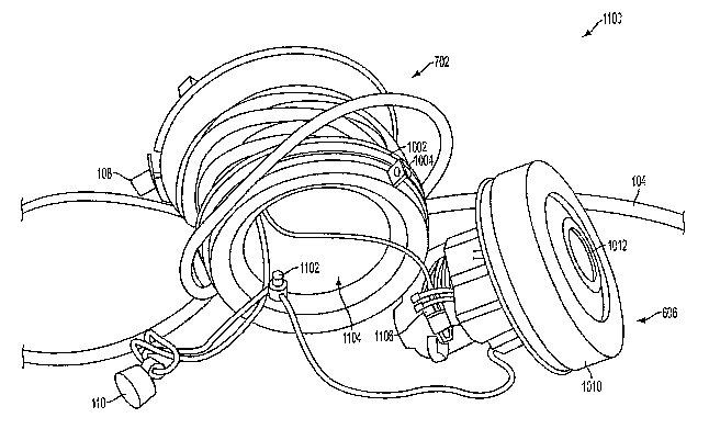
[00048] Fig. 10 is a perspective view 1000 showing the electric motor
606 inserted in an interior space of the cord receiving member 604 cord 104
winding assembly 702 of Fig. 8 according to an exemplary embodiment of the
present invention. As shown, the outer portion (nearest the opening of the
interior
space) of the cord receiving member 604 may include an outer lip 1002, and an
inner lip 1004, which like lip 816, may be made to ride in rails 608a, 608b,
when
cord receiving member 604 is rotated. As shown, in an exemplary embodiment,
inner lip 1004 may include an opening 1006 providing access to other openings
1008, through which, electrical conductors, such as the wires shown, may
extend,
from, e.g., on/off toggle switch 110, to electrc motor 606, and power cord
104. As
shown, electric motor 606, may include a ring 1010, which may be a rubber
ring,
13
CA 02601944 2007-09-04
WO 2006/094189 PCT/US2006/007591
in an exemplary embodiment, which may provide a tight fit for stationary
electric
motor 606 in housing 112. In an exemplary embodiment, incoming vacuum air,
pulled from the dustcup 114 when assembled, may be pulled through intake 1012
by a fan of electric motor 606, through an opening in ring 1010.
[00049] Fig. 11 is a perspective view 1100 showing the electric motor
assembly 606 removed from interior space 1104. (shown inserted in Fig. 10) of
the
cord receiving member 604 cord 104 winding assembly 702 according to an
exemplary embodiment of the present invention. The electric motor assembly
606,
as shown, may include, in an exemplary embodiment, various commonly included
items in a vacuum fan electric motor assembly, including, e.g., but not
limited to,
a vacuum fan, an electric motor, a thermal cutoff 1106 positioned near the
motor
to detect overheating of the motor, various electrical conductors (which
couple the
motor to power cord 104), on/off toggle switch 110, and any of various other
electrical components 1102 (such as, e.g., an on off indicator light, etc.).
In an
exemplary embodiment, the conductors and other components of the vacuum fan
electric motor assembly 606 may be fed into interior space 1104 of the cord
receiving member 604, as shown, and portions, such as switch 110, may extend
out of the interior space via holes such as 1006, 1008 shown in view 1000 of
Fig.
10.
[00050] Fig. 12 is another perspective view 1200 showing the electric
motor assembly 606 removed from the interior space 1104 shown in Fig. 11 of
the
cord receiving member cord winding assembly according to an exemplary
embodiment of the present invention. As shown, the electric motor assembly may
have an exhaust end 1202, which may match up to an opening 1204 in the
interior
space 1204. The exhaust end of the vacuum motor assembly may be in fluid
14
CA 02601944 2007-09-04
WO 2006/094189 PCT/US2006/007591
communication to ventilation openings 808 in the cord receiving member and
openings 212 in the housing 112. As shown, the electrical conductors may be
coupled to the power cord 104 within the interior space of cord receiving
member
604.
[00051] Fig. 13 is another perspective view 1300 showing the cord
receiving member 604 of Fig. 12 with the electric cord 104 unwound from the
cord receiving member, with the electric motor 606 removed from the interior
space 1104 of the cord receiving member 604 cord 104 winding assembly 702
according to the exemplary embodiment of the present invention. As shown, cord
receiving member 604 may include outer cylindrical portion 1304 with an
opening
1302 through which cord 104 may pass to be coupled with the electrical
conductors coupled to the electric motor 606. The cord receiving member 604
may further include interior walls 1306 and 1308 between which, and about
portion 1304, cable 104 may be wound when retracted into housing 112. Interior
walls 1306, 1308 may, in an exemplary embodiment, be perpendicular to the
surface of cylindrical portion 1304. In another exemplary embodiment, the
walls
may be at any acute or obtuse angle to the surface of cylindrical portion
1304.
[00052] Fig. 14 is a more detailed perspective view 1400 of the cord
receiving member 604 cord 104 winding assembly 702 of Fig. 9 further
illustrating a biased retention member 806 and ventilation openings 808, 1404
in
the cord receiving member 604 according to an exemplary embodiment of the
present invention. As shown, retention member 806 may operate similar to a
ratchet. The bias for retention member 806 may include a spring 1402, in an
exemplary embodiment. Cord receiving member 604, in addition to having
ventilation openings 808 in outer layer 814, may further include additional
CA 02601944 2007-09-04
WO 2006/094189 PCT/US2006/007591
ventilation openings 1404, through both openings 808, 1404, exhaust from the
electric motor 606 fan, may pass as shown by 1408. Outer layer 814 may be
coupled to the remainder of cord receiving member 604, by a coupler 1406. In
an
exemplary embodiment, the outer layer 814 may be coupled by a bias in
combination with a screw-type coupler 1406 along axis 612.
[00053] Fig. 15 is a more detailed blow-up perspective view 1500 of the
cord receiving member cord winding assembly further illustrating exhaust flow
out as shown with arrows 1408, 1502a-c through the exemplary ventilation
openings 808, 1404 in the cord receiving member 604 according to an exemplary
embodiment of the present invention.
[00054] Cord receiving member 604 advantageously requires only a
minimal amount of space to contain cord 104, by encircling the motor 606. The
retractable cord assembly as described is described for a handheld vacuum
cleaner, but could easily be used with other compact electric appliance,
and/or
handheld electric appliances such as, e.g., but not limited to, a blower, a
blow
dryer, a drill, a grass cutter, etc. Any device including an electric motor,
or
needing electric power, could similarly include the cord receiving member cord
winding assembly 702 according to the exemplary embodiment.
[00055] Fig. 16 depicts an exemplary view 1600 of an exemplary
embodiment of another cord winding mechanism 604 which may include an
exemplary manual handle 1602 adapted to retract the cord according to another
exemplary embodiment of the present invention. In an exemplary embodiment,
handle 1602 may be collapsible, or removable. Alternatively a spring based
automatically rotatable version may be provided. In an exemplary embodiment, a
cord receiving member of the mechanism 604 may include, e.g., but not limited
16
CA 02601944 2007-09-04
WO 2006/094189 PCT/US2006/007591
to, one or more cross pieces 1604a-c which may be coupled to one or more end
pieces 1606a, 1606b. In one exemplary embodiment two (2) or more cross pieces
1604a-c may be used. In one exemplary embodiment three (3) or more cross
pieces 1604a-c may be used. In another exemplary embodiment, four (4) or more
cross pieces may be used. In one exemplary embodiment, two or more of the
cross pieces 1604a-c may be parallel to one another. In one exemplary
embodiment, two or more of the end pieces 1604a-c may be parallel to one
another. In an exemplary embodiment, one of the end pieces may include an
opening 1608. In an exemplary embodiment, the end pieces may be circular. In
another exemplary embodiment, the end pieces need not be circular, but may be
another shape(e.g., but not limited to, square, triangle, polygon, etc.), so
long as a
way is provided to allow the device to rotate about the axis. In an exemplary
embodiment, the cord receiving member may rotate within a cylindrical shaped
cavity within an appliance. In another exemplary embodiment, the cord
receiving
member may rotate on an which may in some cases include one or more spokes
coupled to the axis (not shown) similar to a bicycle tire.
[00056] Fig. 17 is an exemplary view 1700 of another exemplary
embodiment of another cord winding mechanism 604 which may include be
manual according to another exemplary embodiment of the present invention. In
an exemplary embodiment, a cord receiving member of the mechanism 604 may
include, e.g., but not limited to, a tapering portion 1704. In one exemplary
embodiment, two or more tapering portions 1702, 1704 may be included such as,
e.g., but not limited to, two cones 1702, 1704 substantially aligned point to
point
along an axis. In one exemplary embodiment one of the tapering portions 1702,
1704 may include a cavity 1708. In one exemplary embodiment, the cavity 1708
17
CA 02601944 2007-09-04
WO 2006/094189 PCT/US2006/007591
may be substantially conical. In an exemplary embodiment, the member may
include a handle 1706. The handle 1706 may be collapsible, or removable.
Alternatively a spring based automatically rotatable version may be provided.
In
an exemplary embodiment, the cord receiving member may rotate within a
cylindrical shaped cavity within an appliance. In another exemplary
embodiment,
the cord receiving member may rotate on an which may in some cases include one
or more spokes coupled to the axis (not shown) similar to a bicycle tire.
(00057] The embodiments illustrated and discussed in this specification
are intended only to teach those skilled in the art the best way known to the
inventors to make and use the invention. Nothing in this specification should
be
considered as limiting the scope of the invention. All examples presented are
representative and non-limiting. The above-described embodiments of the
invention may be modified or varied, without departing from the invention, as
appreciated by those skilled in the art in light of the above teachings. It is
therefore to be understood that the invention may be practiced otherwise than
as
specifically described.
18