Language selection

Search

Patent 2601965 Summary

Third-party information liability

Some of the information on this Web page has been provided by external sources. The Government of Canada is not responsible for the accuracy, reliability or currency of the information supplied by external sources. Users wishing to rely upon this information should consult directly with the source of the information. Content provided by external sources is not subject to official languages, privacy and accessibility requirements.

Claims and Abstract availability

Any discrepancies in the text and image of the Claims and Abstract are due to differing posting times. Text of the Claims and Abstract are posted:

  • At the time the application is open to public inspection;
  • At the time of issue of the patent (grant).
(12) Patent Application: (11) CA 2601965
(54) English Title: REMOVABLE DOCTOR BLADE HOLDER WITH LOCKABLE MOUNT
(54) French Title: PORTE-RACLE AMOVIBLE AVEC MONTURE VERROUILLABLE
Status: Deemed Abandoned and Beyond the Period of Reinstatement - Pending Response to Notice of Disregarded Communication
Bibliographic Data
(51) International Patent Classification (IPC):
  • D21G 3/00 (2006.01)
(72) Inventors :
  • ROTHERHAM, JOHN (United Kingdom)
(73) Owners :
  • KADANT WEB SYSTEMS, INC.
(71) Applicants :
  • KADANT WEB SYSTEMS, INC. (United States of America)
(74) Agent: SMART & BIGGAR LP
(74) Associate agent:
(45) Issued:
(86) PCT Filing Date: 2006-02-13
(87) Open to Public Inspection: 2006-08-31
Examination requested: 2007-08-20
Availability of licence: N/A
Dedicated to the Public: N/A
(25) Language of filing: English

Patent Cooperation Treaty (PCT): Yes
(86) PCT Filing Number: PCT/US2006/005119
(87) International Publication Number: WO 2006091427
(85) National Entry: 2007-08-20

(30) Application Priority Data:
Application No. Country/Territory Date
60/655,717 (United States of America) 2005-02-22
NONE (United States of America) 2006-02-13

Abstracts

English Abstract


A doctoring apparatus for doctoring a roll surface comprises a doctor blade, a
blade holder for applying the doctor blade to the roll surface, and a doctor
back having a support surface on which the blade holder is adapted to slide. A
locking bar is subdivided into multiple mechanically interlocked segments and
is mounted by fasteners on the support surface of the doctor back for movement
lengthwise in opposite directions between locked and unlocked positions. The
locking bar is configured and dimensioned to fit loosely within a groove on
the underside of the blade holder. In its unlocked position, the locking bar
permits the blade holder to slide on the doctor back support surface into and
out of an operative position adjacent to the roll surface, hi its locked
position, the locking bar releasably secures the blade holder in its operative
position.


French Abstract

Appareil de raclage pour racler une surface de rouleau comportant une racle, un porte-racle pour appliquer la racle à la surface du rouleau et un arrière de racle possédant une surface du support sur laquelle le porte-racle est adapté de façon à coulisser. Une barre de verrouillage est subdivisée en de multiples segments mécaniquement solidaires et montée par des attaches sur la surface de support de l~arrière de racle pour permettre des mouvements longitudinaux dans des sens opposés entre des positions verrouillées et déverrouillées. La barre de verrouillage est configurée et dimensionnée pour s~ajuster de manière lâche dans une rainure sur le dessous du porte-racle. En position déverrouillée, la barre de verrouillage permet au porte-racle de coulisser sur la surface de support d~arrière de racle pour aller et venir d~une position opérationnelle adjacente à la surface du rouleau. En position verrouillée, la barre de verrouillage fixe de façon amovible le porte-racle à la position opérationnelle.

Claims

Note: Claims are shown in the official language in which they were submitted.

CLAIMS
1. A doctoring apparatus for doctoring a roll surface, comprising:
a doctor blade;
a blade holder for applying said doctor blade to said roll surface, said
blade holder having a groove on its underside;
a doctor back having a support surface on which said blade holder is
adapted to slide;
a locking bar subdivided into multiple mechanically interlocked segments;
fasteners for mounting said locking bar on said support surface for
movement lengthwise in opposite directions between locked and
unlocked positions, said locking bar being configured and
dimensioned to fit loosely within said groove, and, when in its
unlocked position, to permit said blade holder to slide on said support
surface into and out of an operative position adjacent to said roll
surface, said fasteners coacting with said locking bar in its locked
position to releasably secure said blade holder on said support
surface.
2. The doctoring apparatus of claim 1 further comprising an adjustment
mechanism
engageable with one end of said locking bar for shifting said locking bar
relative to
said doctor back between said locked and unlocked positions.
3. The doctoring apparatus of claim 2 wherein said adjustment mechanism
comprises
a threaded spindle fixed with respect to said doctor back, a nut threaded on
said
spindle, and a key straddling said nut and secured to an end segment of said
locking
bar.
4. The doctoring apparatus of claim 1 wherein said fasteners extend through
slots in
said locking bar segments, and wherein said slots have ramped edges coacting
in
wedged relationship with said fasteners when said locking bar is in its locked
position.

Description

Note: Descriptions are shown in the official language in which they were submitted.


CA 02601965 2007-08-20
WO 2006/091427 PCT/US2006/005119
1
REMOVABLE DOCTOR BLADE
HOLDER WITH LOCKABLE MOUNT
REFERENCE TO RELATED APPLICATIONS
This application claims priority from provisional patent application serial
No.
60/655,717 filed February 22, 2005.
BACKGROUND OF THE INVENTION
1. Field of the Invention
This invention relates generally to doctors used in paper making machines,
and is concerned in particular with the provision of a blade holder which is
firmly
locked in its operative position on the doctor back, and which is readily
separable
from the doctor back and removable from the paper making machine for cleaning,
inspection and repair.
2. Description of the Prior Art
The main components of a doctor system include the doctor blade, the blade
holder, the doctor back and the loading mechanism. The doctor blade keeps the
roll
clean and/or sheds the sheet. It must be substantially flat, straight and
parallel, and its
composition must be coinpatible with the roll to be doctored.
The blade holder exerts a uniform, designated load pressure on the blade. It
holds the blade firmly against the roll, accommodates roll irregularities and,
within
limits, compensates for thennal expansion.
The doctor back is in essence the backbone of the doctor. It serves as the
support structure for the blade holder. The loading mechanism pivots the
doctor back
to load the doctor blade against the roll.
Doctor blade holder designs used in recent years are more complex and have
more components than the simpler blade holders used in the past. As a resttlt,
the
more recent holder designs require more routine cleaning and maintenance.
As disclosed for example in U.S. Pat. No. 5,980,692 (Goodnow et al.), it is
known to provide removable blade holders which allow for cleaning and
inaintenance
to be performed off line while the paper machine continues to operate with a
replacement blade holder.
Experience has indicated, however, that removal of the blade holder is

CA 02601965 2007-08-20
WO 2006/091427 PCT/US2006/005119
2
sometimes made difficult due to frictional resistance between mating sliding
surfaces.
SUMMARY OF THE INVENTION
The present invention addresses this problem by mechanically interlocking the
blade holder to the doctor back with linked elements. The linked elements are
strategically positioned to reduce frictional resistance to blade holder
removal and
replacenZent. A locking feature is also incorporated.
These and other features and advantages of the present invention will now be
described in greater detail with reference to the accompanying drawings,
wherein:
BRIEF DESCRIPTION OF THE DRAWINGS
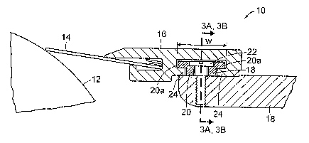
Figure lA is a cross sectional view through a blade holder and mounting
assembly in accordance with the present invention;
Figure 1B is a plan view of one end of the blade holder and mounting
assembly;
Figures 2A and 2B are end elevational views respectively showing the locking
mechanism in the locked and unlocked condition;
Figures 3A and 3B are sectional view taken on line 3-3 of Figure lA, and,
respectively showing the locking mechanism in the locked and unlocked
condition;
Figure 4 is a partial sectional view showing the connection between two linked
elements making up the locking bar; and
Figure 5 is a cross sectional view through an alternative embodiment of a
blade holder and mounting assembly in accordance witll the present invention.
DETAILED DESCRIPTION OF PREFERRED EMBODIMENTS
With references initially to Figures 1A, 1B, 2A and 2B, a blade holder and
mounting assembly in accordance with the present invention is generally
depicted at
10 adjacent to a paper machine roll 12. Roll 12 is driven by conventional
means (not
shown) for rotation about an axis extending in the cross machine direction.
The
doctor assembly includes a doctor blade 14, a blade holder 16 and doctor back
18.
The doctor back is mounted on the paper machine frame for pivotal movement
about
its axis extending in the cross machine direction parallel to the rotational
axis of roll
12. The loading mechanism (not shown) may, for example, include a piston-
cylinder
unit acting through a lever arm to pivot the doctor back about its axis in
order to load

CA 02601965 2007-08-20
WO 2006/091427 PCT/US2006/005119
3
the doctor blade 14, against the surface of the roll 12.
A locking bar 20 is attached by means of screws 22 to a forwardly projecting
shelf of the doctor back 18. The locking bar extends in the cross machine
direction
and has a top with laterally projecting shoulders 20a defining a width "W,"
and a
narrower leg 1Sb projecting downwardly. Thus, the bar 20 has a generally "T"
shaped
cross-section.
The blade holder 16 has a coinplimentary generally "T" shaped slot extending
along its entire length and forming ledges 24 underlying the shoulders 20a of
the
locking bar.
When the blade holder 16 is mounted as shown and in service, its T slot
contacts with the T-shaped bar 20 to establish the requisite mechanical
interengagement, and to provide guide surfaces during longitudinal removal and
replacement of the blade holder.
As shown in Figure 4, the locking bar is preferably made up of individual
elements 20' that are notched at opposite ends with complimentary mechanically
engaged holes 20c and integral pins 20d coacting in a male/female interlocked
relationship. The individual elements 20' can be more readily machined, and
their
interlocked relationship facilitates the task of mounting them on the doctor
back.
As can be best seen in Figures 3A and 3B, the screws 22 extend through slots
26 in the locking bar segments 20'. The slots have ramped side edges 26'. In
Figure
3A, the loclcing bar 20 has been shifted to the right, causing the rainped
side edges 26'
of the slots to become wedged under heads of the screws 22. This is turn urges
the
shoulders 20a of the locking bar segments downwardly against the ledges 24 of
the
blade holder, wliich in turn urges the locking bar blade holder 16 downwardly
into a
clamped position on the shelf of the doctor back. In. Figure 3B, the locking
bar has
been shifted to the left into an unlocked position at which the screw heads
are spaced
above the ramped side edges 26'.
With reference to Figures 2A and 2B, it will be seen that a key 28 is fixed to
a
projecting end segment end of the bar by a screw 30. The key has a bifurcated
base
straddling a nut 32 threaded on a spindle 34 projection from the shelf of the
doctor
back 18. Rotation of the nut in one direction results in the locking bar 20
being pulled
into the locked position, and rotation of the nut in the opposite direction
causes the
locking bar to be pushed into its unlocked position.
In the embodiment illustrated in Figure 5, the locking bar 20 is carried on an

CA 02601965 2007-08-20
WO 2006/091427 PCT/US2006/005119
4
intermediate plate 36 secured to the shelf of the doctor back 18 by screws 38.
Set
screws 40 are threaded into a rearwardly projecting flange of the plate 36.
The set
screws provide a means of imparting micro adjustments to the doctor blade in
order to
match the surface of the roll.
1 claim:

Representative Drawing
A single figure which represents the drawing illustrating the invention.
Administrative Status

2024-08-01:As part of the Next Generation Patents (NGP) transition, the Canadian Patents Database (CPD) now contains a more detailed Event History, which replicates the Event Log of our new back-office solution.

Please note that "Inactive:" events refers to events no longer in use in our new back-office solution.

For a clearer understanding of the status of the application/patent presented on this page, the site Disclaimer , as well as the definitions for Patent , Event History , Maintenance Fee  and Payment History  should be consulted.

Event History

Description Date
Application Not Reinstated by Deadline 2009-02-13
Time Limit for Reversal Expired 2009-02-13
Deemed Abandoned - Failure to Respond to Maintenance Fee Notice 2008-02-13
Inactive: Declaration of entitlement/transfer requested - Formalities 2007-11-13
Inactive: Cover page published 2007-11-08
Inactive: Acknowledgment of national entry - RFE 2007-11-05
Letter Sent 2007-11-05
Inactive: First IPC assigned 2007-10-23
Application Received - PCT 2007-10-22
National Entry Requirements Determined Compliant 2007-08-20
Request for Examination Requirements Determined Compliant 2007-08-20
All Requirements for Examination Determined Compliant 2007-08-20
Application Published (Open to Public Inspection) 2006-08-31

Abandonment History

Abandonment Date Reason Reinstatement Date
2008-02-13

Fee History

Fee Type Anniversary Year Due Date Paid Date
Basic national fee - standard 2007-08-20
Request for examination - standard 2007-08-20
Owners on Record

Note: Records showing the ownership history in alphabetical order.

Current Owners on Record
KADANT WEB SYSTEMS, INC.
Past Owners on Record
JOHN ROTHERHAM
Past Owners that do not appear in the "Owners on Record" listing will appear in other documentation within the application.
Documents

To view selected files, please enter reCAPTCHA code :


To view images, click a link in the Document Description column. To download the documents, select one or more checkboxes in the first column and then click the "Download Selected in PDF format (Zip Archive)" or the "Download Selected as Single PDF" button.

List of published and non-published patent-specific documents on the CPD .

If you have any difficulty accessing content, you can call the Client Service Centre at 1-866-997-1936 or send them an e-mail at CIPO Client Service Centre.


Document
Description 
Date
(yyyy-mm-dd) 
Number of pages   Size of Image (KB) 
Description 2007-08-20 4 184
Drawings 2007-08-20 3 63
Representative drawing 2007-08-20 1 10
Claims 2007-08-20 1 45
Abstract 2007-08-20 1 71
Cover Page 2007-11-08 1 46
Acknowledgement of Request for Examination 2007-11-05 1 177
Reminder of maintenance fee due 2007-11-05 1 113
Notice of National Entry 2007-11-05 1 204
Courtesy - Abandonment Letter (Maintenance Fee) 2008-04-09 1 175
PCT 2007-08-20 2 72
Correspondence 2007-11-05 1 26