Note: Descriptions are shown in the official language in which they were submitted.
CA 02602239 2010-03-01
-1-
Fuel cell heating device and method for operating said fuel cell heating
device
Background of the Invention
The present invention relates to a fuel cell heating device as well as a
method for
operating said fuel cell heating device, in particular a method for starting
up and
shutting down a gas treatment unit in the fuel cell heating device.
Fuel cells, such as polymer membrane fuel cells for example, are sufficiently
known.
Fuel cell heating devices for decentralized energy supply are fed natural gas
through
a gas supply connection, wherein the hydrogen is reformed from hydrogenous
compounds of the natural gas. In a gas treatment unit containing a reformer,
the
hydrocarbons (CnHm) of the natural gas undergo endothermic reform in the
presence of a catalyst by the addition of water vapor, wherein carbon dioxide
(CO2)
and hydrogen (112) form. The reformate also contains residues of carbon
monoxide
(CO), which are selectively oxidized exothermically in a down-stream gas
purification by the addition of oxygen. This forms carbon dioxide (CO2) and
water
(H2O). A gas burner is used for the endothermic steam reformation.
A fuel cell system is known from DE 200 00 857 U1 which has an electrically-
actuated three-way valve in a supply line to a fuel cell. The supply line is
further
provided with a sensor which determines a carbon monoxide concentration in the
supply line to the fuel cell. Upon exceeding a predefined threshold for the
carbon
monoxide, same is prevented from flowing into the fuel cell by the three-way
valve
being appropriately actuated. The gas will be directed past the fuel cell in a
bypass
line. The bypassing gas is burned in a burner for the reformer and the
evaporator. To
further lower the carbon monoxide concentration, it is alternatively likewise
possible
for the gas to cycle through the arrangement a second time. The second
treatment of
the gas serves to further lower the carbon monoxide content.
CA 02602239 2007-06-11
-2-
A staged lean combustion for a rapid start of a fuel-processing system is
known
from DE 102 52 075 Al. For this purpose, two independent burner systems are
known. For this purpose, the initial current of the second burner system is
supplied
to the heat exchanger of a water gas shift reactor/heat exchanger (WGS/HX).
The
gas is furthered from the heat exchanger as output gas. In so doing, the gas
of the
second burner is always kept separate from the gas conducted through the shift
reactor in die PrOx stage.
Reformation normally ensues at temperatures from 500 C to 800 C. The reformer
catalyst cannot have any contact with oxygen because doing so would damage it
or
it would become so heavily oxidized that the desired catalytic effect would no
longer
be obtained. Apart from damage to the reformer caused by oxygen, the reformer
can
also be damaged or prematurely aged by water condensation.
There is therefore the need to prevent the reformer catalyst from being
exposed to an
undefined atmosphere and to avoid water vapor from condensing.
For this purpose, it is known to flush the fuel cell heating device with an
inert gas, in
particular when starting up and shutting down the fuel cell heating device.
Nitrogen
has preferably been used for this purpose to date, same being pumped into or
out of
the system from one or more separate reservoirs.
It is the technical object of the invention to provide a fuel cell heating
device as well
as a method for operating said fuel cell heating device which uses the
simplest
means possible to operate a gas treatment unit in a manner which is safe and
gentle
on its components.
CA 02602239 2010-03-01
-3-
There is therefore the need to prevent the reformer catalyst from being
exposed to an
undefined atmosphere and to avoid water vapor from condensing.
For this purpose, it is known to flush the fuel cell heating device with an
inert gas, in
particular when starting up and shutting down the fuel cell heating device.
Nitrogen has
preferably been used for this purpose to date, same being pumped into or out
of the
system from one or more separate reservoirs.
A fuel cell heating device designed to circulate a system gas such as, for
example,
reformates, anode exhaust gases and/or combustion exhaust gases, through the
gas
treatment during start-up and shut-down is known from US 2003/0138680. A
separate
catalytic burner is provided for this purpose across which the circulating gas
flow is
conducted. In regular operation, no gas flows across the separate catalytic
burner, rather
the fuel cell is supplied by a regular PrOx stage.
Summary of the Invention
The fuel cell heating device according to the present invention differs from
the known
fuel cell heating devices in that no additional components are provided for
the warm-up
and shut-down phases.
It is the technical object of the invention to provide a fuel cell heating
device as well as a
method for operating said fuel cell heating device which uses the simplest
means possible
to operate a gas treatment unit in a manner which is safe and gentle on its
components.
CA 02602239 2010-10-13
E +w
-3a-
According to an aspect of the present invention, there is provided a method
for operating
a fuel cell heating device comprising: circulating a volume of gas in a gas
treatment unit
during the start-up and shut-down of the gas treatment unit, wherein the gas
from an
outlet line of the gas treatment unit is supplied to an inlet line of the gas
treatment unit,
wherein the circulating volume of gas in the gas treatment unit runs through a
gas
purification which is connected to the outlet line and a fuel cell by means of
a valve and,
wherein, when starting up said gas treatment unit, the volume of gas
circulates in the gas
treatment unit upon application of heat by a burner, the volume of gas being
an inert gas
formed from a circulating reformate.
The fuel cell heating device according to the invention comprises a gas
treatment unit
having an inlet line for gas and an outlet line for hydrogenous reformate.
Hydrocarbons
(CnHm) are converted in the gas treatment unit to carbon dioxide (C02) and
hydrogen
(H2) by the addition of water vapor. A circulation line is provided in the
fuel cell heating
device according to the invention
CA 02602239 2010-03-01
-4-
to connect the inlet line and the outlet line. The circulation line enables
the initial
products of the gas treatment unit to be re-fed back to same, whereby a
defined volume of
gas circulates in the gas treatment unit. The gas treatment comprises a
reformer and a
downstream gas purification. The gas purification is hereby preferably
provided in the
outlet line of the gas treatment unit between the reformer and the valve. The
gas fed back
via the circulation line has thus been completely cycled through the gas
treatment unit. By
feeding back the volume of gas to the gas treatment unit, an inert gas can be
produced
from the reformate by supplying air and separating out water. According to the
invention,
the circulation line is connected to the outlet line by at least one valve
which connects the
circulation line with the outlet line of the gas treatment unit. The use of
the valve enables
the circulatory feed of a volume of gas through the circulation line and
thereby cuts off
the gas supply to the fuel cell. For this purpose, a three-way valve, a pair
of valves or
another arrangement of valves can be disposed in the line. In the invention,
the gas
purification is utilized both in the warm-up phase, in which the reformate
circulates, as
well as in the regular operational phase, in which the reformate is supplied
to the fuel
cell.
The gas treatment unit preferably comprises an oxidation unit for the gas
purification.
Carbon monoxide is converted to carbon dioxide and water in the gas
purification by the
addition of air. In the gas treatment process, air is likewise supplied to the
gas treatment
unit.
Brief Description of the Drawings
Figure 1 is a schematic diagram of the fuel cell heating device according to
the present
invention.
CA 02602239 2010-03-01
-5-
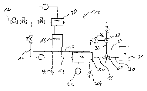
Detailed Description
The fuel cell heating device 10 is fed process gas via a supply line. The
process gas
is fed to a reformer 16 via the line 14. The reformate from the reformer 16 is
supplied to a PrOx stage 20 via a line 18. A supply of air 22 follows in PrOx
stage
20 and the water which forms is discharged by a water trap 24. The gas which
is
formed in the PrOx stage 20 is conveyed by a line 26 through a three-way valve
28
and the three-way valve accordingly set for the fuel cell 32 through line 30.
The gas exiting the fuel cell 32 is fed via a line 34 to a line 36. The line
36 leads into
a burner 3 8 which provides the process heat for the reformer 16. Branching
off from
the line 36 which forms the outlet line for the gas treatment unit is a
circulation line
40 which connects the line 36 with the inlet line 16 for the reformer. The
circulation
line 40 is closed via a three-way valve 37 on the line 36. The three-way valve
37
allows a volume of gas to circulate, inclusive the fuel cell 32.
A circulation pump 42 can additionally be provided in the circulation line 40
to
pump a flow of gas through the circulatory circuit. The circulatory circuit is
formed
by the line 40 which leads via line 14 into the reformer 16 and via line 18
into the
PrOx unit 20, line 26 and the three-way valve 28, and ending at line 36 and
the
three-way valve 37.
Reformation normally ensues at temperatures from 500 C to 800 C. Generally
speaking, the reformer catalyst cannot have any contact with oxygen in the
process
because otherwise the oxygen would either damage the catalyst or heavily
oxidize it.
As long as reformate is produced, the reformer is filled with the process gas,
which
provides a safe atmosphere. A correspondingly safe atmosphere forms when water
44 is supplied to the reformer 16 as water vapor. It must hereby be ensured
that the
CA 02602239 2010-03-01
-6-
water does not condense since doing so would likewise lead to damaging or
premature aging of the catalyst.
The catalyst is not to be subjected to any undefined atmosphere during
operation of
the fuel cell heating device and water as well as residual combustible
reformate
should be removed from the system. In the normal operational state, the system
is
supplied with process heat via the burner 38. In addition, the reformer 16 is
supplied
the educts water 44 and hydrocarbon (CnHm), for example from natural gas. At
temperatures from 500 C to 800 C, the natural gas is reformed, essentially
forming
H2 and CO2. Some percent of residual methane is also contained in the
reformate
since there is not an absolute conversion of the natural gas. The reformate is
moistened since there is more overall water in the system than is necessary
for the
reformation process.
The reformate also contains CO as an unwanted by-product, which can have a
negative impact on the fuel cell operation. In order to remove the CO, the
reformate
is conveyed to a so-called PrOx stage. CO is preferably converted into CO2 and
water there by supplying atmospheric oxygen in the presence of a catalyst.
This
process is also referred to as preferential oxidation. In a secondary
reaction,
however, H2 is also converted to water here with 02. Subsequent the PrOx, the
CO
content has usually been reduced to a few ppm such that the gas can be
supplied to
the fuel cell.
Upon shutting down the system, thus when the system is switched off or in
stand-by
mode, the supply of the water and natural gas educts in the reformer is
stopped and
the supply of process heat ceases. At the same time, the gas flow is rerouted
ahead
of the fuel cell at the three-way valve 28 and channeled to the circulation
line 40.
From there it is fed to the supply line 14 for the reformer. Either an educt
pump
CA 02602239 2007-06-11
-7-
can be used to circulate the gas or also a separate circulation pump 42
integrated into
the line 40. Alternatively, both pumps can also be provided.
The remaining reformate is circulated via the circulation line 40 through the
gas
treatment unit including reformer 16 and the PrOx stage 20. In the process,
air is
supplied to the PrOx stage 20. The oxygen 02 in the air reacts with the H2 of
the
circulation gas to water. This water is discharged from the PrOx by a water
trap 24.
The circulation gas cannot pass through the water trap.
The residual methane within the reformate is further converted in the reformer
into
H2 and CO2 until a balance is reached and no further residual methane is
converted.
The supply of the necessary process heat is still long sufficient due to the
storage
effect of the reformer.
By the continuous circulation in the gas treatment unit and the supply of air
from the
PrOx, H2 from the reformate is nearly completely converted into H2O. Moreover,
the remaining nitrogen accumulates in the circulation gas. After a few
minutes, the
circulation gas consists essentially only of carbon dioxide (CO2) and nitrogen
(N2)
as well as small quantities of methane (CH4) and hydrogen (H2).
This atmosphere ensures the necessary protective effect for the reformer
catalyst. At
the same time, this method also removes excess water from the system, which
extends the life of the catalyst.
When starting up the gas treatment unit, there is an inert gas atmosphere of
carbon
dioxide (CO2) and nitrogen (N2) from the last shut-down cycle as described
above.
This protects the catalyst of the reformer 16 against unwanted oxidation
during the
warm-up.
CA 02602239 2007-06-11
-8-
When starting up the system, the inert gas is circulated in the system in the
same
way as when shutting down. That is to say the inert gas flows back through the
circulation line 40 into the reformer. The air supply 22 of the PrOx stage 20
is
blocked during start-up.
A positive effect of the circulation during start-up is the attaining of a
better
distribution of the process heat in the gas treatment unit and the reformer.
As soon as
the point of water condensation in the reformer is exceeded, the educt water
can be
supplied to the reformer. At the same time, the circulatory circuit can be
opened to
the reformer/burner. The developing water vapor now displaces the inert gas
from
the gas treatment unit and supplies it to the burner. It is thereby also
possible to not
open the circulatory circuit directly to the burner but rather to conduct the
inert gas
to the burner through the fuel cell.
During start-up, the burner is supplied with fuel gas, typically natural gas.
If the
displaced inert gas is now supplied to the burner, a dilution of the necessary
combustion air occurs. This is countervailed by operating the burner at a
higher air
ratio than would be necessary for a clean burn.