Language selection

Search

Patent 2602306 Summary

Third-party information liability

Some of the information on this Web page has been provided by external sources. The Government of Canada is not responsible for the accuracy, reliability or currency of the information supplied by external sources. Users wishing to rely upon this information should consult directly with the source of the information. Content provided by external sources is not subject to official languages, privacy and accessibility requirements.

Claims and Abstract availability

Any discrepancies in the text and image of the Claims and Abstract are due to differing posting times. Text of the Claims and Abstract are posted:

  • At the time the application is open to public inspection;
  • At the time of issue of the patent (grant).
(12) Patent: (11) CA 2602306
(54) English Title: CONSTANT FLOW VALVE
(54) French Title: VANNE A DEBIT CONSTANT
Status: Granted and Issued
Bibliographic Data
(51) International Patent Classification (IPC):
  • G05D 16/06 (2006.01)
  • F16K 1/30 (2006.01)
  • F16K 17/04 (2006.01)
(72) Inventors :
  • NEWTON, JOHN R. (United States of America)
(73) Owners :
  • GLOBAL AGRICULTURAL TECHNOLOGY AND ENGINEERING, LLC
(71) Applicants :
  • GLOBAL AGRICULTURAL TECHNOLOGY AND ENGINEERING, LLC (United States of America)
(74) Agent: SMART & BIGGAR LP
(74) Associate agent:
(45) Issued: 2010-09-28
(86) PCT Filing Date: 2006-02-21
(87) Open to Public Inspection: 2006-09-28
Examination requested: 2007-09-20
Availability of licence: N/A
Dedicated to the Public: N/A
(25) Language of filing: English

Patent Cooperation Treaty (PCT): Yes
(86) PCT Filing Number: PCT/US2006/005941
(87) International Publication Number: WO 2006101641
(85) National Entry: 2007-09-20

(30) Application Priority Data:
Application No. Country/Territory Date
11/358,227 (United States of America) 2006-02-21
60/664,299 (United States of America) 2005-03-22

Abstracts

English Abstract


A regulating valve includes an outer housing (10) comprised of a cap (12)
joined to a base (14). The housing is internally subdivided by a barrier wall
(22) into a head section (24) and a base section (26), the latter being
further subdivided by a modulating assembly (32) into a fluid chamber (23')
and a spring chamber (23"). An inlet (28) and a 90~ outlet (31) in the cap
communicate with the fluid chamber. Fluid at a variable pressure is admitted
into the fluid chamber via the inlet, with the modulating assembly serving to
maintain the fluid exiting the fluid chamber via the outlet at a substantially
constant pressure.


French Abstract

La présente invention se rapporte à une vanne de réglage qui comprend un logement externe (10) constitué d'un bouchon (12) relié à une base (14). L'intérieur du logement est divisé, par une paroi barrière (22), en une section de tête (24) et une section de base (26), cette dernière étant elle-même divisée, par un ensemble de modulation (32), en une chambre de fluide (23') et une chambre à ressort (23''). Un orifice d'entrée (28) et un orifice de sortie (31) à 90° formés dans le bouchon communiquent avec la chambre de fluide. Le fluide à une pression variable est admis dans la chambre de fluide par l'intermédiaire de l'orifice d'entrée, l'ensemble de modulation servant à maintenir le fluide sortant de la chambre de fluide par l'orifice de sortie à une pression sensiblement constante.

Claims

Note: Claims are shown in the official language in which they were submitted.

CLAIMS
1. A regulating valve for receiving fluid at a variable pressure from a fluid
source and
for delivering said fluid at a substantially constant pressure and flow rate
to a fluid
applicator or the like, said valve comprising:
a cup-shaped base having a cylindrical wall segment terminating in an upper
rim,
and an externally projecting first flange;
a cap having an inwardly projecting ledge and an externally projecting second
flange, said cup-shaped base and said cap being configured and dimensioned for
assembly
as a unitary housing, with the cylindrical wall segment of said cup-shaped
base inserted into
said cap, and with the extent of such insertion being limited by the abutment
of said first
flange with said second flange to thereby provide a space between the upper
rim of said
cup-shaped base and the inwardly projecting ledge of said cap;
a barrier wall subdividing the interior of said housing into a head section
and a base
section;
a modulating assembly subdividing said base section into a fluid chamber and a
spring chamber;
an inlet in said cap for connecting said head section to said fluid source;
a port in said barrier wall connecting said head section to said fluid
chamber, said
port being aligned with a central first axis of said valve;
an outlet in said cap communicating with said fluid chamber, said outlet being
aligned on a second axis transverse to said first axis;
a stem projecting from said modulating assembly along said first axis through
said
port into said head section;
a flexible diaphragm supporting said modulating assembly within said housing
for
movement in opposite directions along said first axis, said diaphragm having
an outer
periphery captured in the space between the inwardly projecting ledge of said
cap and a rim
of the cylindrical wall segment of said cup-shaped base;
a spring in said spring chamber, said spring being arranged to resiliently
urge said
modulating assembly into a closed position at which said diaphragm is in
sealing contact
with said barrier wall to thereby prevent fluid flow from said head section
via said port and
fluid chamber to said outlet, said spring acting in concert with said
modulating assembly
and the stem projecting therefrom to modulate the size of said port as an
inverse function of

6
the variable fluid pressure in said input sections whereby the pressure and
flow rate of the
fluid delivered to said outlet is maintained substantially constant, said
valve being
automatically actuated when the pressure of the fluid acting on said
modulating assembly
exceeds a threshold level, and being automatically closed when said pressure
drops below
said threshold level.
2. A regulating valve for receiving a fluid at a variable pressure from a
fluid source and
for delivering said fluid at a substantially constant pressure and flow rate
to a fluid
applicator or the like, said valve comprising:
a first housing component having a cylindrical wall segment terminating in an
upper
rim, and an externally projecting first flange;
a second housing component having an inwardly projecting ledge and an
externally
projecting second flange, said first and second housing components being
configured and
dimensioned for assembly as a unitary housing, with the cylindrical wall
segment of said
first housing component inserted into said second housing component, and with
the extent
of such insertion being limited exclusively by the abutment of said first
flange with said
second flange to thereby provide a space axially remote from said flanges and
defined
between the upper rim of the cylindrical wall segment of said first housing
component and
the inwardly projecting ledge of said second housing component;
an inlet and an outlet in said housing, said inlet and outlet being adapted
for
connection respectively to said fluid source and said fluid applicator;
a barrier wall arranged between said inlet and outlet to subdivide the
interior of said
housing;
a port in said barrier wall providing a flow path between said inlet and said
outlet;
a modulating assembly suspended within said housing by a flexible diaphragm,
said
modulating assembly serving to modulate the size of said flow path as an
inverse function
of the variable fluid pressure at said inlet, whereby the pressure and flow
rate of the fluid
delivered to said outlet is maintained substantially constant, said valve
being automatically
actuated when the pressure of the fluid acting on said modulating assembly
exceeds a
threshold level, and being automatically closed when said pressure drops below
said
threshold level, said diaphragm having an outer periphery captured in the
space between the
inwardly projecting ledge of said second housing component and the rim of the
cylindrical
wall segment of said first housing component.

7
3. The regulating valve of claim 2 wherein said inlet and said outlet are
located in said
second housing component.

Description

Note: Descriptions are shown in the official language in which they were submitted.


CA 02602306 2009-12-23
CONSTANT FLOW VALVE
BACKGROUND OF THE INVENTION
1. Field of the Invention
This invention relates to generally to fluid valves, and is concerned in
particular with
a regulating valve that is normally closed, that is opened by a variable fluid
pressure above a
selected threshold level, and that when open, serves to deliver the fluid at a
constant
pressure and flow rate.
2. Description of the Prior Art
Regulating valves for the above-mentioned type are known, as disclosed for
example in U.S. Patent Nos. 6,026,850 and 6,209,578. While these known valves
operate in
an entirely satisfactory manner, for some uses, their design has proven to be
overly
complex, expensive, and difficult to incorporate in restricted spaces within
fluid dispensing
equipment, e.g., carbonated, and non-carbonated soft drink dispensers.
SUMMARY OF THE INVENTION
According to an aspect of the invention there is provided a regulating valve
for
receiving fluid at a variable pressure from a fluid source and for delivering
the fluid at a
substantially constant pressure and flow rate to a fluid applicator or the
like, the valve
comprising: a cup-shaped base having a cylindrical wall segment terminating in
an upper
rim, and an externally projecting first flange; a cap having an inwardly
projecting ledge and
an externally projecting second flange, the cup-shaped base and the cap being
configured
and dimensioned for assembly as a unitary housing, with the cylindrical wall
segment of
said cup-shaped base inserted into the cap, and with the extent of such
insertion being
limited by the abutment of the first flange with the second flange to thereby
provide a space
between the upper rim of the cup-shaped base and the inwardly projecting ledge
of the cap;
a barrier wall subdividing the interior of the housing into a head section and
a base section;
a modulating assembly subdividing the base section into a fluid chamber and a
spring
chamber; an inlet in the cap for connecting the head section to the fluid
source; a port in the
barrier wall connecting the head section to the fluid chamber, the port being
aligned with a
central first axis of the valve; an outlet in the cap communicating with the
fluid chamber,
the outlet being aligned on a second axis transverse to the first axis; a stem
projecting from
the modulating assembly along the first axis through the port into the head
section; a

CA 02602306 2009-12-23
2
flexible diaphragm supporting the modulating assembly within the housing for
movement in
opposite directions along the first axis, the diaphragm having an outer
periphery captured in
the space between the inwardly projecting ledge of the cap and a rim of the
cylindrical wall
segment of the cup-shaped base; a spring in the spring chamber, the spring
being arranged
to resiliently urge the modulating assembly into a closed position at which
the diaphragm is
in sealing contact with the barrier wall to thereby prevent fluid flow from
the head section
via the port and fluid chamber to the outlet, the spring acting in concert
with the modulating
assembly and the stem projecting therefrom to modulate the size of the port as
an inverse
function of the variable fluid pressure in the input sections whereby the
pressure and flow
rate of the fluid delivered to the outlet is maintained substantially
constant, the valve being
automatically actuated when the pressure of the fluid acting on the modulating
assembly
exceeds a threshold level, and being automatically closed when the pressure
drops below
the threshold level.
According to another aspect of the invention there is provided a regulating
valve for
receiving a fluid at a variable pressure from a fluid source and for
delivering the fluid at a
substantially constant pressure and flow rate to a fluid applicator or the
like, the valve
comprising: a first housing component having a cylindrical wall segment
terminating in an
upper rim, and an externally projecting first flange; a second housing
component having an
inwardly projecting ledge and an externally projecting second flange, the
first and second
housing components being configured and dimensioned for assembly as a unitary
housing,
with the cylindrical wall segment of the first housing component inserted into
the second
housing component, and with the extent of such insertion being limited
exclusively by the
abutment of the first flange with the second flange to thereby provide a space
axially remote
from the flanges and defined between the upper rim of the cylindrical wall
segment of the
first housing component and the inwardly projecting ledge of the second
housing
component; an inlet and an outlet in the housing, the inlet and outlet being
adapted for
connection respectively to the fluid source and the fluid applicator; a
barrier wall arranged
between the inlet and outlet to subdivide the interior of the housing; a port
in the barrier
wall providing a flow path between the inlet and the outlet; a modulating
assembly
suspended within the housing by a flexible diaphragm, the modulating assembly
serving to
modulate the size of the flow path as an inverse function of the variable
fluid pressure at the
inlet, whereby the pressure and flow rate of the fluid delivered to the outlet
is maintained
substantially constant, the valve being automatically actuated when the
pressure of the fluid

CA 02602306 2009-12-23
3
acting on the modulating assembly exceeds a threshold level, and being
automatically
closed when the pressure drops below the threshold level, the diaphragm having
an outer
periphery captured in the space between the inwardly projecting ledge of the
second
housing component and the rim of the cylindrical wall segment of the first
housing
component.
BRIEF DESCRIPTION OF THE DRAWING
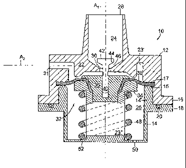
The drawing is a sectional view through a regulating valve in accordance with
the
present invention, the valve being shown in its open condition.
DETAILED DESCRIPTION OF PREFERRED EMBODIMENT
With reference to the drawing, a regulating valve in accordance with the
present
invention is generally depicted at 10. The valve includes an outer housing
having a cap 12
joined to a cup-shaped base 14 at mating exterior flanges 16, 18, with an O-
ring seal 20
interposed therebetween.
The housing is internally subdivided by a barrier wall 22 into a head section
24 and
a base section 26. An inlet 28 in the cap 12 is adapted to be connected to a
fluid supply (not
shown) having a pressure that can vary from below to above a threshold level.
The inlet 28
and a central port 30 in the barrier wall 22 are aligned along a central axis
Al of the valve.
An outlet port 31, also in the cap 12, is aligned on a second axis A2
transverse to the first
axis A,.
A modulating assembly 32 cooperates with the barrier wall 22 to subdivide the
base
section into a fluid chamber 23' segregated from a spring chamber 23". The
modulating
assembly serves to prevent fluid flow through the valve when the fluid
pressure at the inlet
28 is below the threshold pressure. When the fluid pressure at the inlet
exceeds the
threshold pressure, the modulating assembly serves to accommodate fluid flow
from the
head section 24 through port 30 into chamber 23' at a constant pressure and
flow rate, and
from there through outlet port 31. Either the outlet port 31 or a downstream
orifice or flow
restrictor (not shown) serves to develop a back pressure in fluid chamber 23'.
The modulating assembly 32 includes a piston comprised of a hollow shell 34
and a
central plug 36. The piston is supported for movement in opposite directions
along axis A,
by a flexible annular diaphragm 38. The inner periphery of the diaphragm is
captured
between the shell 34 and plug 36. The cup shaped base 14 has a cylindrical
wall segment

CA 02602306 2009-12-23
4
14' received within the cap 12. The outer periphery of the diaphragm is
captured between
an upper rim 15 of the wall segment 14' and an inwardly projecting interior
ledge 17 on the
cap.
A stem 40 on the piston plug 36 projects through the port 30 into the head
section
24. An enlarged head 42 on the stem has a tapered underside 44 that coacts
with a tapered
surface 46 of the barrier wall to modulate the size of the flow path through
the port 30 as an
inverse function of the varying fluid pressure in the input section, with the
result being to
deliver fluid to the outlet 31 at a constant pressure and now rate.
A compression spring 48 in the spring chamber 23" is captured between an
underside surface of shell 34 and the bottom wall 52 of the housing base 14.
The spring
urges the modulating assembly 32 towards the barrier wall 22. When the fluid
pressure at
the inlet 28 is below the threshold pressure, spring 48 serves to urge the
diaphragm 38
against the barrier wall 22, thus preventing fluid flow from the fluid chamber
23' to the
outlet 31'. As the fluid pressure exceeds the threshold pressure, the
resilient closure force of
spring 48 is overcome, allowing the piston assembly to move away from the
barrier wall,
and allowing the modulating function of the coacting tapered surfaces 44, 46
to commence.
An opening 50 in the bottom wall 52 serves to vent the volume beneath
diaphragm 38 to the
surrounding atmosphere.
I claim:

Representative Drawing
A single figure which represents the drawing illustrating the invention.
Administrative Status

2024-08-01:As part of the Next Generation Patents (NGP) transition, the Canadian Patents Database (CPD) now contains a more detailed Event History, which replicates the Event Log of our new back-office solution.

Please note that "Inactive:" events refers to events no longer in use in our new back-office solution.

For a clearer understanding of the status of the application/patent presented on this page, the site Disclaimer , as well as the definitions for Patent , Event History , Maintenance Fee  and Payment History  should be consulted.

Event History

Description Date
Common Representative Appointed 2019-10-30
Change of Address or Method of Correspondence Request Received 2018-03-28
Maintenance Request Received 2018-01-29
Maintenance Request Received 2017-01-30
Maintenance Request Received 2016-01-28
Maintenance Request Received 2014-01-28
Maintenance Request Received 2012-12-27
Grant by Issuance 2010-09-28
Inactive: Cover page published 2010-09-27
Pre-grant 2010-07-16
Inactive: Final fee received 2010-07-16
Notice of Allowance is Issued 2010-01-29
Letter Sent 2010-01-29
Notice of Allowance is Issued 2010-01-29
Inactive: Approved for allowance (AFA) 2010-01-26
Amendment Received - Voluntary Amendment 2009-12-23
Inactive: S.30(2) Rules - Examiner requisition 2009-06-30
Letter Sent 2008-01-11
Inactive: Cover page published 2007-12-12
Inactive: Declaration of entitlement/transfer requested - Formalities 2007-12-11
Inactive: Acknowledgment of national entry - RFE 2007-12-10
Letter Sent 2007-12-10
Inactive: Correspondence - Formalities 2007-11-19
Inactive: Single transfer 2007-11-05
Inactive: First IPC assigned 2007-10-25
Application Received - PCT 2007-10-24
National Entry Requirements Determined Compliant 2007-09-20
Request for Examination Requirements Determined Compliant 2007-09-20
All Requirements for Examination Determined Compliant 2007-09-20
Application Published (Open to Public Inspection) 2006-09-28

Abandonment History

There is no abandonment history.

Maintenance Fee

The last payment was received on 2010-01-22

Note : If the full payment has not been received on or before the date indicated, a further fee may be required which may be one of the following

  • the reinstatement fee;
  • the late payment fee; or
  • additional fee to reverse deemed expiry.

Please refer to the CIPO Patent Fees web page to see all current fee amounts.

Owners on Record

Note: Records showing the ownership history in alphabetical order.

Current Owners on Record
GLOBAL AGRICULTURAL TECHNOLOGY AND ENGINEERING, LLC
Past Owners on Record
JOHN R. NEWTON
Past Owners that do not appear in the "Owners on Record" listing will appear in other documentation within the application.
Documents

To view selected files, please enter reCAPTCHA code :


To view images, click a link in the Document Description column. To download the documents, select one or more checkboxes in the first column and then click the "Download Selected in PDF format (Zip Archive)" or the "Download Selected as Single PDF" button.

List of published and non-published patent-specific documents on the CPD .

If you have any difficulty accessing content, you can call the Client Service Centre at 1-866-997-1936 or send them an e-mail at CIPO Client Service Centre.


Document
Description 
Date
(yyyy-mm-dd) 
Number of pages   Size of Image (KB) 
Description 2007-09-20 3 119
Drawings 2007-09-20 1 25
Abstract 2007-09-20 2 77
Claims 2007-09-20 2 63
Representative drawing 2007-12-11 1 16
Cover Page 2007-12-12 1 48
Description 2009-12-23 4 199
Claims 2009-12-23 3 112
Representative drawing 2010-09-03 1 19
Cover Page 2010-09-03 2 54
Maintenance fee payment 2024-01-30 4 143
Acknowledgement of Request for Examination 2007-12-10 1 176
Reminder of maintenance fee due 2007-12-10 1 112
Notice of National Entry 2007-12-10 1 203
Courtesy - Certificate of registration (related document(s)) 2008-01-11 1 105
Commissioner's Notice - Application Found Allowable 2010-01-29 1 163
PCT 2007-09-20 5 172
Correspondence 2007-12-10 1 26
Correspondence 2007-11-19 2 85
Fees 2010-01-22 1 35
Correspondence 2010-07-16 1 38
Fees 2012-01-09 1 68
Fees 2012-12-27 1 67
Fees 2014-01-28 2 77
Maintenance fee payment 2016-01-28 2 80
Maintenance fee payment 2017-01-30 2 81
Maintenance fee payment 2018-01-29 2 82