Note: Descriptions are shown in the official language in which they were submitted.
CA 02602448 2007-09-21
WO 2006/104936 PCT/US2006/010930
DAMPER DOOR CONTROL FROM ADAPTIVE DEFROST CONTROL
CROSS-REFERENCE TO RELATED PATENT APPLICATIONS
[0001] This patent application claims the benefit of U.S. Provisional Patent
Application
No. 60/666,682 filed March 31, 2005, the teachings and disclosure of which are
hereby
incorporated in their entireties by reference thereto.
FIELD OF THE INVENTION
[0002] The invention relates generally to refrigerators and, more
particularly, to
controlling the air flow between a freezer compartment and a fresh food
compartment in a
refrigerator.
BACKGROUND OF THE INVENTION
[0003] Many modern refrigeration units include a fresh food compartment for
storing
food above a freezing temperature. The fresh food compartYnent is normally
isolated from a
main or freezer compartment for storing food below the freezing temperature.
Often, the
temperatures of the fresh food and freezer compartments can be separately
controlled. To
provide cooling to the fresh food compartment, the fresh food compartment is
typically
equipped with an active damper door controlled by a damper motor. When the
damper door
is open, typically the evaporator fan is energized to move cooling air from
inside of the
freezer coinpartment into the fresh food compartment. When the damper door is
closed, the
fresh food compartment is isolated from the freezer compartment and its
temperature can
change separately from the freezer compartment.
[0004] In a typical refrigeration unit, the fresh food compartment is equipped
with its
own thermostatic switch to permit thermostatic control of the temperature of
the fresh food
compartment. This thermostatic switch detects when the temperature of the
fresh food
compartment exceeds a threshold, indicating that cool air from the freezer
compartment must
be introduced into the fresh food compartment. When the thermostatic switch
detects this
condition, the thermostatic switch changes state to its "hot" condition, in
which it delivers
electrical power to the damper motor to open the damper. When the fresh food
compartment
cools, the thermostatic switch again changes state to its "cool" condition, in
which it delivers
electrical power to the damper motor to close the damper.
CA 02602448 2007-09-21
WO 2006/104936 PCT/US2006/010930
[0005] It is further known that the efficiency of the typical refrigeration
unit can be
enhanced by reducing the amount of frost that builds up on the heat exchanger
within the
freezer compartment. Modern systems, therefore, are generally of the self-
defrosting type.
To this end, they employ a heater specially positioned and controlled to
slightly heat the heat
exchanger to cause melting of frost build-up on the heat exchanger. These
defrost heaters are
controlled pursuant to defrost cycle algorithms and configurations. As a
result, these
refrigerator-freezers undergo two general cycles or modes, a cooling cycle or
mode and a
defrost cycle or mode. During the cooling cycle, a compressor is connected to
a line voltage
and the compressor is cycled on and off by means of a thermostat, i.e., the
compressor is
actually run only when the enclosure becomes sufficiently warm to require
cooling. During
the defrost cycle, the compressor is disconnected from the line voltage and a
defrost heater is
connected to the line voltage. The defrost heater is turned off by means of a
temperature
sensitive switch in proximity to the heat exchanger after the frost has been
melted away, or
otherwise by programmatic control.
[0006] Unfortunately, conventional refrigeration systems do nothing to prevent
the
damper door from being open during the defrost cycle if the refrigerator
compartment calls
for cooling while the freezer compartment is in a defrost cycle. Accordingly,
warm moist air
is permitted to flow through the damper door duct into the fresh food
compartment. It is not
desirable to have warm moist air in a compartment where food is meant to be
kept cool and
fresh. Accordingly, there is a need in the art to prevent the damper door from
opening during
the defrost cycle.
BRIEF SUMMARY OF THE INVENTION
[0007] The invention provides an adaptive defrost control method and device
for
controlling a damper door during a defrost cycle. Before entering the defrost
cycle, the
adaptive defrost control logic determines if the damper door is open. If the
damper door is
open, the defrost cycle is suspended until the door is closed. If the damper
door is closed, the
adaptive defrost control logic prevents the opening of the damper door.
[0008] In one embodiment of the present invention, the system of the present
invention
activates an electronic barrier between the damper door motor and a power
supply so that the
damper door may not be opened during the defrost cycle. In one embodiment the
barrier is a
triac located between the main power supply and a thermostatic switch for
controlling the
temperature of the fresh food compartment. In another embodiment of the
invention, the
barrier is a triac located between the main power supply and the damper door
motor. After
2
CA 02602448 2007-09-21
WO 2006/104936 PCT/US2006/010930
the defrost cycle is completed, the adaptive defrost control logic removes the
barrier to allow
operation of the damper door motor. The damper door may then be opened and
closed as
necessary.
[0009] Other aspects, objectives and advantages of the invention will become
more
apparent from the following detailed description when taken in conjunction
with the
accompanying drawings.
BRIEF DESCRIPTION OF THE DRAWINGS
[0010] The accompanying drawings incorporated in and forming a part of the
specification illustrate several aspects of the present invention and,
together with the
description, serve to explain the principles of the invention. In the
drawings:
[0011] FIG. 1 is a schematic diagram of a refrigeration unit in accordance
with the
present invention;
[0012] FIG. 2 is a schematic diagram of a control circuit for controlling the
refrigeration
unit in accordance with one embodiment of the present invention;
[0013] FIG. 3 is a schematic diagram of a control circuit for controlling the
refrigeration
unit in accordance with a second embodiment of the present invention; and
[0014] FIG. 4 is a flow diagram illustrating a control logic method in
accordance with the
present invention.
[0015] While the invention will be described in connection with certain
preferred
embodiments, there is no intent to limit it to those embodiments. On the
contrary, the intent
is to cover all alternatives, modifications and equivalents as included within
the spirit and
scope of the invention as defined by the appended claims.
DETAILED DESCRIPTION OF THE INVENTION
[0016] Referring to FIG. 1, the major electrical components of a refrigeration
unit 100
such as, for example, a commercial or domestic refrigerator-freezer are
schematically
illustrated. As will be more fully explained below, the present invention
prevents warm
moist air from passing into a fresh food compartment from a freezer
compartment when the
3
CA 02602448 2007-09-21
WO 2006/104936 PCT/US2006/010930
refrigeration unit 100 undergoes a defrost cycle. As such, food within the
fresh food
compartment is advantageously maintained in a fresh condition for a longer
period of time.
[0017] Still referring to FIG. 1, the refrigeration unit 100 includes a first
or main
compartment such as a freezer compartment 101 and a second fresh food
compartment 102.
The first and second compartments 101, 102 are separately thermostatically
controlled.
Under thermostatic control, the freezer and fresh food compartments 101, 102
are coupled
together by opening a damper door 104 to uncover an opening or passage
interposed between
the two compartments 101, 102. When the damper door 104, which is moveable by
a damper
motor 105, is driven or otherwise biased opened, a flow of air is permitted to
pass between
the two adjacent compartments 101, 102. When the damper door 104 is closed,
air is
inhibited or prevented from flowing between the two neighboring compartments
101, 102. In
other words, the damper door 104 regulates the flow of air between the
comparhnents 101,
102 to control the temperature of the fresh food compartment 101.
[0018] The damper door 104 is generally coupled to and driven by an electric
damper
motor 105. The damper door 104 is, in some situations, also driven closed by
the electric
damper motor 105. In other situations, the damper door 104 is simply
resiliently biased
closed as well known in the art.
[0019] Inside of the freezer compartment 101 is a main thermostat 106 that has
as a
primary component a thermostatic switch 107. In a typical application, the
thermostat 106 is
adjustable so that the temperature of the freezer compartment 101 is
maintainable at different
selected temperatures. Inside of the fresh food compartment 102 is a fresh
food thermostat
108 that has as a primary component a second thermostatic switch 109. In a
typical
application, the thermostat 108 is also adjustable so that the temperature of
the fresh food
compartment 102 is maintainable at different selected temperatures.
[0020] Refrigeration unit 100 is cooled by a heat transfer engine that
facilitates heat
transfer from the freezer compartment 101 by the cyclical compression,
condensation,
decompression and evaporation of a thermally coupled refrigerant captured in a
thermodynamic loop. The thermodynamic loop includes an evaporator 110,
compressor 111,
and condenser 112. As the refrigerant passes through evaporator 110, which is
located inside
of the freezer compartment 101, the refrigerant evaporates from a liquid to a
gaseous state,
absorbing heat transferred from the freezer compartment 101 into the
refrigerant. The
primarily gaseous refrigerant is delivered at the outlet of evaporator 110 to
compressor 111.
4
CA 02602448 2007-09-21
WO 2006/104936 PCT/US2006/010930
[0021] The compressor 111 compresses the primarily gaseous refrigerant
received from
evaporator 110 and delivers the compressed refrigerant to condenser 112. The
compressed
refrigerant is generally delivered by the application of a mechanical force
generated by an
electric motor integrated within the compressor 111. After leaving the
compressor 111, the
compressed, high pressure refrigerant passes through condenser 112. While
passing through
the condenser 112, heat is transferred from the refrigerant to the enviromnent
external to
freezer compartment 101 as the refrigerant condenses from a primarily gaseous
state to a
primarily liquid state. The primarily liquid refrigerant then passes back into
the inlet of
evaporator 110 to complete the cycle.
[0022] To facilitate and promote heat transfer between the refrigerant in the
coils of the
evaporator 110 and the air within the freezer compartment 101, a fan 113 is
included in the
refrigeration unit 100. Specifically, an evaporator fan 113 is disposed in the
freezer
compartment 101 to circulate the air in the freezer. The evaporator fan 113 is
specifically
able to produce a flow of air that passes over and around the coils of the
evaporator 110. This
flow of air past the coils of the evaporator 110 encourages the exchange of
heat from the air
in freezer compartment 101 to the refrigerant. As such, the refrigerant in the
coils is able
draw heat out of, and absorb heat from, the air within the freezer compartment
101.
[0023] As the fresh food compartment 102 warms, the fresh food thermostat 108
senses
higher temperatures. When the sensed temperature reaches or exceeds a high
temperature
limit, the fresh food thermostat 108 closes thermostatic switch 109 to send a
signal to damper
motor 105 to open the damper door 104. With the damper door 104 open, colder
air from the
freezer compartment 101 is passed or circulated into the fresh food
compartment 102. The
temperature in the fresh food compartment 101 is lowered by the inflow of
colder air from
the freezer compartment 101 until the temperature falls to a temperature that
is at or below
the high temperature limit of the fresh food thermostat 108. At that point,
the fresh food
thermostat 108 opens the thermostatic switch 109 to send a signal to the
damper motor 105 to
close damper door 104.
[0024] To ensure that frost build up on the condenser 112 does not reduce the
effectiveness of the cooling cycle, refrigeration unit 100 further includes a
defrost heater 120.
The defrost heater 120 is situated near the evaporator 110 to melt frost from
the evaporator
during a defrost cycle. Operation of the defrost heater 120 is controlled by
an adaptive
defrost control logic unit 121 as commonly known in the art.
CA 02602448 2007-09-21
WO 2006/104936 PCT/US2006/010930
[0025] As previously described, in the conventional refrigeration unit the
damper door
may be left open or permitted to open during the defrost cycle thereby
allowing heat and
moisture into the fresh food compartment 102. In an embodiment of the present
invention,
the damper door 104 is closed or forced to remain closed during the defrost
cycle. As such,
heat and moisture are prevented from entering the fresh food compartment 102.
As
schematically illustrated in FIG. 2, a control circuit 200 for closing the
damper door during a
defrost cycle is shown.
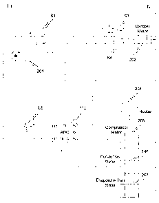
[0026] With reference to FIG. 2, an adaptive defrost controller (ADC) 203
coordinates
the operation of a compressor motor 205, a condenser motor 206, a defrost
heater 204, and a
triac 201. In the illustrated embodiment, the compressor motor 205 is
connected between
terminal T6 of the ADC 203 and a ground line N and is actuated by the ADC
during a
cooling cycle when cooling of the freezer coinpartment is required. Condenser
motor 206 is
connected between terminal T7 of the ADC 203 and the ground line N and is
actuated by the
ADC during a cooling cycle. Evaporator fan motor 207 is connected between
terminal T8 of
the ADC 203 and the ground line N and is actuated by the ADC during a cooling
cycle.
Heater 204 is connected to terminal T4 of the ADC 203 and is actuated by the
ADC during a
defrost cycle. The triac 201 is connected between power line L1 and contact
"a" of switch Sl
(e.g., such as switch 109 in FIG. 1) and is actuated by the ADC 203 via a
control line
connected to terminal T3 of the ADC. The triac 201 is actuated by ADC 203
during a defrost
cycle to deny current to contact "a" of switch S 1. The ADC 203 is further
connected to
power line Ll at terminal T1 and ground line N at terminal T4.
[0027] When a thermostat 106 senses that a temperature in the freezer
compartment 101
has risen above a specified level, the thermostat instructs the refrigeration
unit 100 to enter a
cooling cycle. During the cooling cycle, the thermostat 106 commands the
switch S2 (e.g.,
such as switch 107 in FIG. 1) to close such that current is permitted to flow
from contact "d"
of switch S2 to contact "e" of switch S2 and, in turn, to terminal T2 of the
ADC 203. When
the ADC 203 receives this current signal at the terminal T2, the ADC 203
actuates the
compressor motor 205, the condenser fan motor 206, and the evaporator fan
motor 207.
When the thermostat 106 senses that the temperature in the freezer compartment
101 has
been cooled to a specified level, the thermostat 106 instructs the switch S2
to once again
open. With the switch S2 open, a current no longer flows into the terminal T2
of the ADC
203. Based on the lack of current signal at the terminal T2, the ADC 203
deactivates the
compressor motor 205, the condenser fan motor 206, and the evaporator fan
motor 207 and
the cooling cycle is generally competed.
6
CA 02602448 2007-09-21
WO 2006/104936 PCT/US2006/010930
[0028] When a thermostat 108 senses that a temperature in the fresh food
compartment
102 has risen above a specified level, the thermostat 108 instructs the
refrigeration unit 100 to
enter a cold air transfer cycle. The thermostat 108 causes the switch S 1 to
move from an
initial position, where the contacts "a" and "b" are coupled, to a secondary
position, where the
contacts "a" and "c" are coupled. The secondary position of the switch S 1
permits current to
flow from the power line Ll, through the closed triac 201, through the switch
S1, and to
contact "f' of switch S3 and contact "i" of switch S4. The switch S3 is in a
position to
connect contact "f' to contact "h" and the switch S4 is in a position to
connect contact "i" to
contact "k". As such, current is permitted to flow into and energize or
actuate the damper
motor 202. The energized damper motor 202 is adapted to drive the damper door
104 (FIG.
1) open such that cold air is transferred from the freezer compartment 110 to
the fresh food
compartment 102 through the opening 103.
[0029] Because the damper door 104 is mechanically coupled to the switch S3,
as
comnlonly known in the art, when the damper door 104 has attained an open
position the
switch S3 is manipulated to connect contact "g" to contact "h" and the switch
S4 is
manipulated to connect contact "j" to contact "k". Since terminal "b" of
switch S 1 is not
coupled to the power line Ll, the flow of current to the damper motor 202
ceases after the
damper door 104 has achieved the open position. Notably, switch S3 and switch
S4 are
redundant and open and close one at a time to prevent stalling of the damper
door 104 in a
partially-open position upon a loss of power.
[0030] When the thermostat 108 senses that the temperature in the fresh food
compartment 102 has appropriately dropped, the thermostat instructs the switch
Sl to open.
With the switch S 1 open, the damper motor 202 no longer receives a current
and the damper
door 104 is able to close. To close, the damper door 104 is generally drawn
away from the
open position by a biasing member such as, for example, a spring or other
resilient member.
[0031] In accordance with the adaptive control logic, the refrigeration unit
100 is
occasionally instructed to enter a defrost cycle to melt away any frost (i.e.,
ice) that has
accumulated on or around the coils of the evaporator 110. During the defrost
cycle, the ADC
203 activates the defrost heater 204 to melt the frost from the evaporator
110. Operation of
the heater 120 produces warm and moist air (e.g., air that is at a temperature
above freezing
and has a relative humidity higher than normally found in conventional
freezers) such that
any ice or condensation adhered to the coils is removed or reduced. Due to the
melting ice
and evaporating condensation, the air in the freezer compartment 101 becomes
warm and
moist as the temperature inside the compartment 101 rises.
7
CA 02602448 2007-09-21
WO 2006/104936 PCT/US2006/010930
[0032] In addition to activating the defrost heater 120, the ADC 203 also
ensures that the
compressor motor 205, the condenser motor 206, and the evaporator fan motor
207 are
inactive. Since defrost cycle is producing heat, and the cooling cycle is
absorbing heat, the
two cycles are controlled and activated in a mutually exclusive fashion by the
ADC 203. As
a result, even if the switch S2 is instructed to close by thermostat 106 in an
attempt to activate
the cooling cycle, the ADC 203 ignores the closure of the switch. Therefore,
until the
completion of the defrost cycle, the components 205, 206, 207 remain
deactivated regardless
of the position of switch S2. In other words, the heat absorbing (or
exchanging) process
remains idle in favor of the defrost cycle.
[0033] Also during the defrost cycle, the ADC 203 instructs the triac 201 to
close. As
illustrated in FIG. 2, the deactivated triac 201 restricts current from
flowing to the damper
motor 202. Therefore, even if switch Sl is instructed to close by thermostat
108 in an
attempt to begin the cold air transfer cycle, no current can flow to the
damper motor 202. As
such, the position of the switch S 1 becomes meaningless during the defrost
cycle.
Resultantly, the opening 103 remains impeded by the damper door 104 and the
wa.rm moist
air that is generated in the freezer comparhnent 101 during the defrost cycle
is not permitted
to escape into the fresh food compartment 102.
[0034] As schematically illustrated in FIG. 3, another embodiment of a control
circuit
300 for retaining the damper door in a closed position during a defrost cycle
is shown. With
reference to FIG. 3, an adaptive defrost controller (ADC) 303 coordinates the
operation of a
compressor motor 305, a condenser motor 306, a defrost heater 304, and a triac
301. The
coinpressor motor 305 is connected between terminal T6 of the ADC 303 and a
ground line N
and is actuated by the ADC during a cooling cycle. The condenser motor 306 is
connected
between terminal T7 of the ADC 303 and the ground line N and is actuated by
the ADC
during a cooling cycle. The evaporator fan motor 307 is connected between
terminal T8 of
the ADC 303 and the ground line N and is actuated by ADC 303 during a cooling
cycle. The
heater 304 is connected to terminal T5 of the ADC 303 and is actuated by the
ADC during a
defrost cycle. The triac 301 is connected between power line Ll and damper
motor 302 and
is actuated by the ADC 303 via a control line connected to terminal T3 of the
ADC 303. The
triac 301 is actuated by the ADC 303 during a defrost cycle to restrict
current from flowing to
the damper motor 302. In other words, the triac 301 prevents the damper motor
302 from
being activated or operating during the defrost cycle. The ADC 303 is further
connected to
the power line Ll at terminal Tl and the ground line N at T4.
8
CA 02602448 2007-09-21
WO 2006/104936 PCT/US2006/010930
[0035] When a thermostat 106 senses that a temperature in the freezer
compartment 101
has risen above a specified level, the thermostat 106 instructs the
refrigeration unit 300 to
enter a cooling cycle. During the cooling cycle, the switch S2 closes to
permit current to
flow from contact d of switch S2 to contact e of switch S2 and, in turn, to
terminal T2 of
ADC 303. When the ADC 303 receives this current signal at terminal T2, the ADC
actuates
the compressor motor 305, the condenser motor 306, and the evaporator fan
motor 307.
When the thermostat 106 senses that the temperature in the freezer compartment
101 has
been cooled to a specified level, the thermostat instructs the switch S2 to
once again open.
With the switch S2 open, a current no longer flows into the terminal T2 of the
ADC 303.
Based on the lack of current signal at T2, the ADC deactivates the compressor
motor 305, the
condenser motor 306, and the evaporator fan motor 307 and the cooling cycle is
generally
completed.
[0036] When a thermostat 108 senses that a temperature in the fresh food
compartment
102 has risen above a specified level, the thermostat causes the switch S5 to
move to from an
initial (i.e., open) position, where the contacts "m" and "n" are uncoupled,
to a secondary
(i.e., closed) position, where the contacts "m" and "n" are coupled, to enter
a cold air transfer
cycle. The secondary switch position completes a circuit between terminal Tl 1
and terminal
T9 of the ADC 303. Upon detection of this completed circuit, the ADC 303 opens
triac 301
to permit current to flow to the damper door motor 302. The energized damper
motor 302
resultantly drives the damper door 104 open to allow cold air from the freezer
compartment
101 to flow into the fresh food compartment 102 through the opening 103.
[0037] Because the damper door 104 is mechanically coupled to the switch S6,
as
commonly known in the art, when the damper door 104 has attained an open
position, the
switch S6 is manipulated to uncouple and disconnect contacts "q" and "r." With
the switch
S6 opened, the circuit between terminal T9 and terminal T10 of the ADC 303 is
broken and
the ADC is resultantly notified that the damper door is in an open position.
[0038] When the thermostat 108 senses that the temperature in the fresh food
compartment 102 has cooled to an acceptable level, the thermostat instructs
the switch S5 to
open. As such, the connection between terminal T11 and terminal T9 is broken.
When this
connection is broken, the ADC 303 recognizes this condition and closes the
triac 301. With
the triac closed, the damper motor 302 is no longer energized and the damper
door 104 is
permitted to close. The closing of the damper door 104 causes the switch S6,
which is
mechanically coupled to the damper door, to close. As such, the circuit
between terminal T9
9
CA 02602448 2007-09-21
WO 2006/104936 PCT/US2006/010930
and terminal T10 is reestablished and the ADC 303 is advised that the damper
door has been
closed.
[0039] In accordance the adaptive control logic, the refrigeration unit 300 is
occasionally
instructed to enter a defrost cycle to melt away any frost (i.e., ice) that
has accumulated on or
around the coils of the evaporator 110. During the defrost cycle, the ADC 303
activates the
defrost heater 304 to melt the frost from the evaporator 110. As before, the
heat and warm air
produced by the heater 120 are permitted to flow over and around the coils of
the evaporator
110 such that any ice or condensation adhered to the coils is removed or
reduced. Due to the
melting ice and evaporating condensation, the air in the freezer compartment
101 becomes
warm and moist as the temperature inside the compartment 101 rises.
[0040] In addition to activating the defrost heater 120, the ADC 303 also
ensures that the
compressor motor 305, the condenser motor 306, and the evaporator fan motor
307 are
inactive. Since defrost cycle is producing heat, and the cooling cycle is
absorbing heat, the
two cycles are controlled and activated in a mutually exclusive fashion by the
ADC 303. As
a result, even if the switch S2 is instructed to close by thermostat 106 in an
attempt to activate
the cooling cycle, the ADC 303 ignores the closure of the switch. Therefore,
until the
completion of the defrost cycle, the components 305, 306, 307 remain
deactivated regardless
of the position of switch S2. In other words, the heat absorbing (or
exchanging) process
remains idle in favor of the defrost cycle.
[0041] Also during the defrost cycle, the ADC 303 instructs the triac 301 to
close. As
illustrated in FIG. 3, the closed triac 301 forins an electronic barrier to
the flow of current to
the damper motor 302. Therefore, even if switch S5 should be instructed to
close by
thermostat 108 in an attempt to initiate the cold air transfer cycle, no
current can flow to the
damper motor 302. As such, the position of switch S5 is irrelevant during the
defrost cycle.
Resultantly, the opening 103 remains impeded by the damper door 104 and the
warm moist
air that is generated in the freezer compartment 101 during the defrost cycle
is not permitted
to escape into the fresh food compartment 102.
[0042] In light of the above embodiments of the invention and as will be
appreciated by
those skilled in the art, when the refrigeration unit 100 is in the defrost
cycle, closure of the
switches S 1 and S5 by the thermostat 108, which would normally begin the cold
air transfer
cycle, has no effect since the current path to the damper motor 202, 302 is
cut off by the
deactivation of the triac 201, 301. With no actuating or energizing current,
the damper door
104 cannot be driven open and the warm, moist air that generated during the
defrost cycle
CA 02602448 2007-09-21
WO 2006/104936 PCT/US2006/010930
cannot, no matter what happens to switches S 1 and S5, pass from the freezer
compartment
101 to the fresh food compartment 102. Furthermore, those skilled in the art
will recognize
that while the triacs 201, 301 are described in detail and illustrated in both
FIGS. 2 and 3,
different types and varieties of devices and/or switches are employable within
the control
circuits 200, 300 to prevent a current from flowing.
[0043] In addition to the conventional known adaptive defrost control logic,
the flow
diagram of FIG. 4 illustrates additional logic for ensuring that the damper
door 104 is closed
during the defrost cycle. When the control circuit 200, 300 in the
refrigeration unit 100 is
started 399, the adaptive defrost control logic determines 400 if the damper
door is open
before entering the defrost cycle. If the damper door is open, the defrost
cycle is suspended
until the door is closed. If the damper door is closed, the adaptive defrost
control logic cuts
power 401 to the damper door motor (e.g., provides a barrier between the
damper door motor
and a power supply) so that the damper door cannot be opened during the
defrost cycle. With
the damper door disengaged from the power supply, the defrost cycle is
performed 402.
After the defrost cycle is completed, the adaptive defrost control logic
removes the barrier
from between the damper door motor and a power supply such that the damper
motor is once
again permitted to run 403. With the damper motor once again free to drive the
damper door,
the protection cycle is ended 404 and the damper door can open and closed as
necessary to
transfer colder air from the freezer compartment to the fresh food compartment
during
normal operation of the appliance until the next defrost cycle is begun.
[0044] All references, including publications, patent applications, and
patents, cited
herein are hereby incorporated by reference to the same extent as if each
reference were
individually and specifically indicated to be incorporated by reference and
were set forth in
its entirety herein.
[0045] The use of the terms "a" and "an" and "the" and similar referents in
the context of
describing the invention (especially in the context of the following claims)
are to be
construed to cover both the singular and the plural, unless otherwise
indicated herein or
clearly contradicted by context. The terms "comprising," "having,"
"including," and
"containing" are to be construed as open-ended terms (i.e., meaning
"including, but not
limited to,") unless otherwise noted. Recitation of ranges of values herein
are merely
intended to serve as a shorthand method of referring individually to each
separate value
falling within the range, unless otherwise indicated herein, and each separate
value is
incorporated into the specification as if it were individually recited herein.
All methods
described herein can be performed in any suitable order unless otherwise
indicated herein or
11
CA 02602448 2007-09-21
WO 2006/104936 PCT/US2006/010930
otherwise clearly contradicted by context. The use of any and all examples, or
exemplary
language (e.g., "such as") provided herein, is intended merely to better
illuminate the
invention and does not pose a limitation on the scope of the invention unless
otherwise
claimed. No language in the specification should be construed as indicating
any non-claimed
element as essential to the practice of the invention.
[0046] Preferred embodiments of this invention are described herein, including
the best
mode known to the inventors for carrying out the invention. Variations of
those preferred
embodiments may become apparent to those of ordinary skill in the art upon
reading the
foregoing description. The inventors expect skilled artisans to employ such
variations as
appropriate, and the inventors intend for the invention to be practiced
otherwise than as
specifically described herein. Accordingly, this invention includes all
modifications and
equivalents of the subject matter recited in the claims appended hereto as
pennitted by
applicable law. Moreover, any combination of the above-described elements in
all possible
variations thereof is encompassed by the invention unless otherwise indicated
herein or
otherwise clearly contradicted by context.
12