Language selection

Search

Patent 2602678 Summary

Third-party information liability

Some of the information on this Web page has been provided by external sources. The Government of Canada is not responsible for the accuracy, reliability or currency of the information supplied by external sources. Users wishing to rely upon this information should consult directly with the source of the information. Content provided by external sources is not subject to official languages, privacy and accessibility requirements.

Claims and Abstract availability

Any discrepancies in the text and image of the Claims and Abstract are due to differing posting times. Text of the Claims and Abstract are posted:

  • At the time the application is open to public inspection;
  • At the time of issue of the patent (grant).
(12) Patent: (11) CA 2602678
(54) English Title: LOAD EQUALIZING ROPE TERMINATION AND METHOD
(54) French Title: EXTREMITE DE CABLE A EQUILIBRAGE DE CHARGE ET METHODE D'UTILISATION
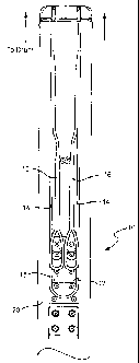
Status: Granted and Issued
Bibliographic Data
(51) International Patent Classification (IPC):
  • F16G 11/00 (2006.01)
  • B66D 01/34 (2006.01)
(72) Inventors :
  • CAMPBELL, GEOFFREY GEORGE (Australia)
  • MCNEIL, ALEXANDER MCKECHRAN HARDIE (Australia)
(73) Owners :
  • JLG INDUSTRIES, INC.
(71) Applicants :
  • JLG INDUSTRIES, INC. (United States of America)
(74) Agent: KIRBY EADES GALE BAKER
(74) Associate agent:
(45) Issued: 2010-08-03
(22) Filed Date: 2007-09-18
(41) Open to Public Inspection: 2008-04-17
Examination requested: 2007-11-15
Availability of licence: N/A
Dedicated to the Public: N/A
(25) Language of filing: English

Patent Cooperation Treaty (PCT): No

(30) Application Priority Data:
Application No. Country/Territory Date
11/581,783 (United States of America) 2006-10-17

Abstracts

English Abstract

A load equalizing rope termination serves to prevent a load imbalance between a pair of rope leads of a rope termination. The rope termination includes an end section such as an end loop and the pair of rope leads attached to a pair of rope ends. A rope termination fitting includes a base support member over which the end section is supported, and a pair of load equalizing support members disposed upstream of the base support member and over which the rope ends are supported. The engagement between the rope ends and the equalizing support members prevents a load imbalance of the rope leads.


French Abstract

Une extrémité de câble à équilibrage de charge permet d'éviter les déséquilibres de charge entre une paire de fils de câble d'une extrémité de câble. L'extrémité de câble inclut une section d'extrémité, telle qu'une boucle, et la paire de fils de câble fixée à une paire d'extrémités de câble. Le montage de l'extrémité de câble comprend un élément de soutien de base par-dessus lequel la section d'extrémité est soutenue, et une paire d'éléments de soutien à équilibrage de charge disposée en amont de l'élément de soutien de base et par-dessus laquelle les extrémités de câble sont soutenues. L'accrochage des extrémités de câble et des éléments de soutien à équilibrage empêche les déséquilibres de charge des fils de câble.

Claims

Note: Claims are shown in the official language in which they were submitted.

CLAIMS
1. A load equalizing rope termination comprising:
a pair of rope ends;
a rope termination attached to the rope ends and defining an end section and
a pair of rope leads; and
a rope termination fitting comprising:
a base support member over which the end section is supported, and
a pair of load equalizing support members disposed upstream of the
base support member and over which the rope ends are supported, the engagement
between the rope ends and the load equalizing support members preventing a
load
imbalance of the rope leads.
2. A load equalizing rope termination according to claim 1, wherein the
load equalizing support members are spaced from the base support member and
aligned across a width of the base support member.
3. A load equalizing rope termination according to claim 1, wherein the
base support member and the load equalizing support members are angled in a
direction opposite from a load direction.
4. A load equalizing rope termination according to claim 1, wherein the
rope termination is spliced with the rope ends.
5. A load equalizing rope termination according to claim 1, wherein the
rope ends support a load, each of the rope ends being capable of independently
supporting the load, and wherein the load equalizing rope termination is
assembled
such that in upon breakage of either rope end or the rope termination, the
other
rope end will support the load.
6. A load equalizing rope termination according to claim 1, wherein the
end section comprises an end loop.
7

7. A load equalizing rope termination comprising:
a pair of rope ends;
a rope termination attached to the rope ends and defining an end section and
a pair of rope leads; and
a rope termination fitting comprising means coupled with the rope ends for
preventing a load imbalance of the rope leads.
8. A load equalizing rope termination according to claim 7, wherein the
end section comprises an end loop.
9. A load equalizing rope termination according to claim 8, wherein the
preventing means comprises:
a base support member over which the end loop is supported; and
a pair of load equalizing support members disposed upstream of the base
support member and over which the rope ends are supported.
10. A method of preventing a load imbalance on a rope termination
defining an end section and a pair of rope leads, the method comprising:
attaching the rope termination to a pair of rope ends;
securing the end section over a base support member; and
securing the rope ends over a corresponding pair of load equalizing support
members disposed upstream of the base support member.
11. A rope termination for at least two ropes supporting a load, the rope
termination being configured to prevent a load imbalance on the ropes and
being
designed so that in the event of a breakage in any of the ropes, at least one
other
rope will independently support the load.
8

Description

Note: Descriptions are shown in the official language in which they were submitted.


CA 02602678 2007-09-18
TITLE OF THE INVENTION
LOAD EQUALIZING ROPE TERMINATION AND METHOD
CROSS-REFERENCES TO RELATED APPLICATIONS
[0001] (NOT APPLICABLE)
STATEMENT REGARDING FEDERALLY
SPONSORED RESEARCH OR DEVELOPMENT
[0002] (NOT APPLICABLE)
BACKGROUND OF THE INVENTION
[0003] The present invention relates to force distribution and load balancing
and, more particularly, to a load equalizing rope termination and method that
prevent a load imbalance on a pair of rope leads.
[0004] A lifting or winch system is known where a driving pulley, cable,
chain, tape, rope or the like (hereinafter "rope") is attached to a rotating
drum or
other motive power source. At its end, the rope is secured to the object to be
lifted
or pulled. The drum is fixed relative to the object to be moved. As the drum
is
rotated, the rope is taken up around the drum, and the object to be moved is
pulled.
[0005] In order to provide a level of redundancy, a pair of ropes with
respective rope ends may be secured between the drum and the object to be
lifted.
A problem arises with this arrangement, however, if a load imbalance occurs on
the rope ends. In the event of such a load imbalance, the object to be moved
may
be skewed or otherwise unevenly displaced, which thereby may prevent proper
operation of the device.
1
1115921

CA 02602678 2007-09-18
BRIEF SUMMARY OF THE INVENTION
[0006] It would thus be desirable to develop structure cooperable with the
rope termination that would prevent a load imbalance of the rope ends. The
rope
termination and method described herein utilize a rope termination fitting
including one or more load equalizing support members. The support members
receive a portion of the rope or an attachment to the rope to prevent the rope
from
an imbalanced load. The structure additionally ensures independence of the
ropes
as each is capable of supporting the load independently in the event one of
the
ropes fails.
[0007] In an exemplary embodiment of the invention, a load equalizing rope
termination includes a pair of rope ends; a rope termination attached to the
rope
ends and defining an end section such as an end loop and a pair of rope leads;
and
a rope termination fitting. The rope termination fitting includes a base
support
member over which the end section is supported, and a pair of load equalizing
support members disposed upstream of the base support member and over which
the rope ends are supported. The engagement between the rope ends and the load
equalizing support members prevents a load imbalance of the rope leads.
[0008] The load equalizing support members are preferably spaced from the
base support member and aligned across a width of the base support member. The
base support member and the load equalizing support members may be angled in a
direction opposite from a load direction. In a preferred arrangement, the rope
termination is spliced with the rope ends.
[0009] In another exemplary embodiment of the invention, a load
equalizing rope termination includes a pair of rope ends; a rope termination
attached to the rope ends and defining an end section and, a pair of rope
leads; and
2
1115921

CA 02602678 2007-09-18
a rope termination fitting having structure coupled with the rope ends for
preventing a load imbalance of the rope leads.
[0010] In yet another exemplary embodiment of the invention, a method of
preventing a load imbalance on a rope termination defining an end section and
a
pair of rope leads includes the steps of attaching the rope termination to a
pair of
rope ends; securing the end section over a base support member; and securing
the
rope ends over a corresponding pair of load equalizing support members
disposed
upstream of the base support member.
BRIEF DESCRIPTION OF THE DRAWINGS
[0011] These and other aspects and advantages of the present invention will
be described in detail with reference to the accompanying drawings, in which:
[0012] FIGURE 1 shows the load equalizing rope termination in use
including the rope and rope termination fitting;
[0013] FIGURE 2 is a perspective view of the rope termination fitting;
[0014] FIGURE 3 is a side view of the rope termination fitting; and
[0015] FIGURES 4A-9 show alternative concepts for the rope termination.
DETAILED DESCRIPTION OF THE INVENTION
[0016] With reference to FIG. 1, like a conventional redundant
arrangement, a load equalizing rope termination includes a pair of rope ends
16.
The rope ends 16 are attached at an opposite end to a rotating drum or the
like.
The ropes are configured such that either rope is independently capable of
supporting the load, thus providing an added margin of safety in the event
that one
of the ropes breaks.
3
1115921

CA 02602678 2007-09-18
[0017] The rotating drum or the like may be fixed and the load movable at
the distal ends of the ropes; or the drum may be attached to the movable load
and
move with the load with the distal ends of the rope fixed; or a combination of
both. In a preferred arrangement, the drum is fixed, and the load, such as a
work
platform or the like, is restrained to move along a load path (e.g., with
wheels on
rails). If the ropes 16 are not identical in length, one of the ropes will
carry a
disproportionate share of the load. This is particularly so if the ropes are
high in
stiffness such as wire ropes or some pre-stretched polymer ropes or the like.
If the
ropes do not carry an equal share of the load, one rope may become slack
enough
to jump grooves on a grooved winch drum; the load may skew creating side loads
on the wheels with increasing friction, wear and energy losses; or one rope
may
wear faster and thereby have a shorter useful life.
[0018] To address these concerns while maintaining redundant independent
support by the rope ends 16, a rope termination 10 defining an end section
such as
an end loop 12 and a pair of rope leads 14 is spliced or otherwise attached to
the
rope ends 16. Any suitable manner of splicing the ropes together may be used,
and the specific splicing method does not form part of the invention. As such,
no
further description will be provided.
[0019] A rope termination fitting 18 is fixed to an object to be moved (load)
20 via suitable connectors. The rope termination fitting 18 includes a base
support
member 22 over which the end loop 12 is supported, and two load equalizing
support members 24 disposed upstream of the base support member 22 and over
which the rope ends 16 are supported. The term "upstream" in this context is
intended to encompass a direction in which a force on the rope termination 10
is
pulling the rope termination fitting 18. In FIG. 1, the upstream direction is
upward.
4
1115921

CA 02602678 2007-09-18
[0020] As shown in FIG. 2, the load equalizing support members 24 are
spaced from the base support member 22 and are generally aligned across a
width
of the base support member 22. Additionally, with reference to FIG. 3, the
base
support member 22 and the load equalizing support members 24 are angled in a
direction opposite from the load direction. In this manner, when a load is
applied
to the rope termination 10 (upward in FIG. 3), the downward angled base
support
member 22 and load equalizing support members 24 prevent the rope termination
from slipping off. A cover (not shown) over the rope termination fitting 18
further prevents the rope termination 10 from slipping off.
[0021] In use, as a rotating drum or other motive force applies a load to the
rope termination 10, the end loop 12 or other end section is pulled against
the base
support member 22 while the rope ends 16 remain generally slack, and the rope
termination fitting 18 and the movable object 20 to which it is attached are
driven
in the load direction. The rope ends 16 supported on the load equalizing
support
members 24 prevent a load imbalance of the rope leads 14. That is, an
unbalanced
load on the object to be moved 20, via friction, anomalies in the drum or the
like
may cause one of the rope leads 14 to be pulled at a different rate or load,
thereby
causing a load imbalance on the rope leads 14. Upon such an occurrence, the
rope
ends 16 engaging the respective load equalizing support members 24 prevent the
rope leads from being driven unevenly, thereby preventing a load imbalance on
the rope leads 14.
[0022] As noted, the configuration also serves to maintain a redundant load
support as a safety feature in the event one of the rope leads 14, the primary
ropes,
or rope ends 16 fails. During normal operation, the end loop 12 supports the
load.
As such, the rope ends 16 remain slack and are not subjected to routine wear.
If
one of the rope leads 14 fails, the rope ends 16 will engage the respective
load
5
1115921

CA 02602678 2007-09-18
equalizing support members 24 to support the load. Moreover, in the event that
one of the rope ends 16 fails, the second rope end 16 will support the load.
[0023] FIGS. 4A-9 show alternative rope terminations including alternative
end sections that function to prevent a load imbalance of the two ropes, and
that
are designed so that in the event of a breakage in any one rope or rope
connector,
there will always be at least one other rope supporting the load.
[0024] The rope termination fitting described herein includes one or more
load equalizing support members that receive rope ends or an attachment to the
rope ends to prevent the ropes from being subject to an imbalanced load.
[0025] While the invention has been described in connection with what is
presently considered to be the most practical and preferred embodiments, it is
to
be understood that the invention is not to be limited to the disclosed
embodiments,
but on the contrary, is intended to cover various modifications and equivalent
arrangements included within the spirit and scope of the appended claims.
6
1115921

Representative Drawing
A single figure which represents the drawing illustrating the invention.
Administrative Status

2024-08-01:As part of the Next Generation Patents (NGP) transition, the Canadian Patents Database (CPD) now contains a more detailed Event History, which replicates the Event Log of our new back-office solution.

Please note that "Inactive:" events refers to events no longer in use in our new back-office solution.

For a clearer understanding of the status of the application/patent presented on this page, the site Disclaimer , as well as the definitions for Patent , Event History , Maintenance Fee  and Payment History  should be consulted.

Event History

Description Date
Maintenance Request Received 2024-09-13
Maintenance Fee Payment Determined Compliant 2024-09-13
Common Representative Appointed 2019-10-30
Change of Address or Method of Correspondence Request Received 2018-01-09
Inactive: Office letter 2014-06-26
Grant by Issuance 2010-08-03
Inactive: Cover page published 2010-08-02
Inactive: Final fee received 2010-05-20
Pre-grant 2010-05-20
Letter Sent 2010-04-14
Notice of Allowance is Issued 2010-04-14
Inactive: Approved for allowance (AFA) 2010-03-31
Amendment Received - Voluntary Amendment 2009-11-03
Amendment Received - Voluntary Amendment 2009-10-13
Inactive: S.30(2) Rules - Examiner requisition 2009-08-13
Application Published (Open to Public Inspection) 2008-04-17
Inactive: Cover page published 2008-04-16
Amendment Received - Voluntary Amendment 2008-03-31
Letter Sent 2008-02-15
Inactive: IPC assigned 2008-02-14
Inactive: First IPC assigned 2008-02-14
Inactive: IPC assigned 2008-02-14
Request for Examination Received 2007-11-15
Request for Examination Requirements Determined Compliant 2007-11-15
All Requirements for Examination Determined Compliant 2007-11-15
Application Received - Regular National 2007-10-25
Inactive: Filing certificate - No RFE (English) 2007-10-25

Abandonment History

There is no abandonment history.

Maintenance Fee

The last payment was received on 2009-08-21

Note : If the full payment has not been received on or before the date indicated, a further fee may be required which may be one of the following

  • the reinstatement fee;
  • the late payment fee; or
  • additional fee to reverse deemed expiry.

Patent fees are adjusted on the 1st of January every year. The amounts above are the current amounts if received by December 31 of the current year.
Please refer to the CIPO Patent Fees web page to see all current fee amounts.

Owners on Record

Note: Records showing the ownership history in alphabetical order.

Current Owners on Record
JLG INDUSTRIES, INC.
Past Owners on Record
ALEXANDER MCKECHRAN HARDIE MCNEIL
GEOFFREY GEORGE CAMPBELL
Past Owners that do not appear in the "Owners on Record" listing will appear in other documentation within the application.
Documents

To view selected files, please enter reCAPTCHA code :


To view images, click a link in the Document Description column. To download the documents, select one or more checkboxes in the first column and then click the "Download Selected in PDF format (Zip Archive)" or the "Download Selected as Single PDF" button.

List of published and non-published patent-specific documents on the CPD .

If you have any difficulty accessing content, you can call the Client Service Centre at 1-866-997-1936 or send them an e-mail at CIPO Client Service Centre.


Document
Description 
Date
(yyyy-mm-dd) 
Number of pages   Size of Image (KB) 
Description 2007-09-17 6 245
Claims 2007-09-17 2 74
Abstract 2007-09-17 1 17
Drawings 2007-09-17 8 137
Representative drawing 2008-03-16 1 5
Description 2009-10-12 7 251
Claims 2009-10-12 2 64
Drawings 2009-10-12 8 136
Drawings 2009-11-02 8 107
Representative drawing 2010-07-13 1 6
Filing Certificate (English) 2007-10-24 1 157
Acknowledgement of Request for Examination 2008-02-14 1 177
Reminder of maintenance fee due 2009-05-19 1 111
Commissioner's Notice - Application Found Allowable 2010-04-13 1 166
Correspondence 2010-05-19 1 37
Correspondence 2014-06-25 1 25