Language selection

Search

Patent 2602685 Summary

Third-party information liability

Some of the information on this Web page has been provided by external sources. The Government of Canada is not responsible for the accuracy, reliability or currency of the information supplied by external sources. Users wishing to rely upon this information should consult directly with the source of the information. Content provided by external sources is not subject to official languages, privacy and accessibility requirements.

Claims and Abstract availability

Any discrepancies in the text and image of the Claims and Abstract are due to differing posting times. Text of the Claims and Abstract are posted:

  • At the time the application is open to public inspection;
  • At the time of issue of the patent (grant).
(12) Patent: (11) CA 2602685
(54) English Title: METHOD AND APPARATUS FOR CENTRIFUGAL SEPARATION ENHANCEMENT
(54) French Title: PROCEDE ET APPAREIL D'AMELIORATION DE LA SEPARATION CENTRIFUGE
Status: Granted and Issued
Bibliographic Data
(51) International Patent Classification (IPC):
  • B01D 21/26 (2006.01)
(72) Inventors :
  • BROWNE, NEALE (United States of America)
  • IVAN, CATALIN (United States of America)
(73) Owners :
  • M-I L.L.C.
(71) Applicants :
  • M-I L.L.C. (United States of America)
(74) Agent: FINLAYSON & SINGLEHURST
(74) Associate agent:
(45) Issued: 2013-07-16
(86) PCT Filing Date: 2006-04-11
(87) Open to Public Inspection: 2006-10-19
Examination requested: 2011-02-22
Availability of licence: N/A
Dedicated to the Public: N/A
(25) Language of filing: English

Patent Cooperation Treaty (PCT): Yes
(86) PCT Filing Number: PCT/US2006/013351
(87) International Publication Number: WO 2006110675
(85) National Entry: 2007-09-28

(30) Application Priority Data:
Application No. Country/Territory Date
60/670,528 (United States of America) 2005-04-11

Abstracts

English Abstract


A method for removing low gravity solids from an oil-based drilling fluid
includes directing the drilling fluid into a first inlet of a first line in
fluid communication with a centrifuge, injecting steam into the drilling fluid
through a second inlet in the first line, wherein the second inlet is upstream
from the centrifuge, directing the commingled drilling fluid and steam into
the centrifuge, rotating the centrifuge at a rotational speed sufficient to
separate solids from liquids, collecting solids from a solids discharge, and
collecting effluent from an effluent outlet, wherein the effluent has low
gravity solids in an amount less than 1.5%.


French Abstract

L'invention concerne un procédé d'élimination de solides à faible gravité provenant de boues de forage à base d'huile consistant à orienter les boues de forage dans une première entrée d'une première ligne en communication par voie fluide avec une centrifugeuse, à injecter de la vapeur dans les boues de forage à travers une seconde entrée ménagée dans la première ligne, la seconde entrée étant en amont de la centrifugeuse, à orienter les boues de forage et la vapeur mélangées dans la centrifugeuse, à faire tourner la centrifugeuse à une vitesse rotative suffisante pour séparer les solides des liquides, à collecter les solides à partir d'une décharge de solides et à collecter l'effluent à partir d'une sortie d'effluent, l'effluent présentant des solides à faible gravité en quantité inférieure à 1,5 %.

Claims

Note: Claims are shown in the official language in which they were submitted.

WHAT IS CLAIMED IS:
1. A method for reducing low gravity solids from an oil-based drilling
fluid comprising:
directing the drilling fluid into a first inlet of a first line in fluid
communication with a
centrifuge;
injecting stream into the drilling fluid through a second inlet in the first
line to provide
commingled drilling fluid and steam, wherein the second inlet is upstream from
the centrifuge;
directing the commingled drilling fluid and steam into the centrifuge;
rotating the centrifuge at a rotational speed sufficient to separate solids
from liquids;
collecting solids from a solids discharge; and
collecting effluent from an effluent outlet, wherein the effluent has low
gravity solids in
an amount less than 1.5%.
2. The method of claim 1, wherein the low gravity solids have a lower
density than barite
and include colloidal particles and the effluent includes less than 5.5%
solids, with the low
gravity solids less than the 1.5%.
3. The method of claim 1 or 2, wherein the steam is injected into the
second inlet with a
flow rate of 0.05 to 0.10 gallons per minute water equivalent.
4. The method of claim 2 or 3, wherein the steam is at a pressure in the
range of 88 to 100
pounds per square inch.
5. The method of claim 2 or 3, wherein the steam is at a temperature in the
range of 320
to 350 degrees Fahrenheit.
6. The method of claim 1 or 2, wherein the steam is injected into the first
line in an amount
in the range of 0.25 to 0.4% by volume of the commingled drilling fluid and
steam.

7. An apparatus for removing low gravity solids from an oil-based drilling
fluid comprising:
a centrifuge having an inlet for receiving fluid, a solids discharge, and an
effluent outlet;
a steam generator providing steam to the drilling fluid upstream from the
centrifuge inlet;
wherein the steam is injected into the drilling fluid in an amount sufficient
to separate
liquid and solids particles such that the separated liquid includes less than
5.5% solid particles;
and
wherein the solid particles in the effluent from the effluent outlet include
low gravity
solids in an amount less than 2%.
8. The apparatus of claim 7, wherein the solid particles in the effluent
from the effluent
outlet include low gravity solids in an amount less than 1.5%.
9. The apparatus of claim 7, wherein the solid particles in the effluent
from the outlet have
0% low gravity solids.
10. The apparatus of claim 7, wherein the steam is injected into the
drilling fluid with a flow
rate of 0.05 to 0.10 gallons per minute water equivalent.
11. The apparatus of claim 10, wherein the steam is injected into the
drilling fluid with a
pressure in the range of 88 to 100 pounds per square inch.
12. The apparatus of claim 10, wherein the steam is injected into the
drilling fluid with a
temperature in the range of 320 to 350 degrees Fahrenheit.
13. The apparatus of claim 10, wherein the steam is injected into the
drilling fluid in an
amount in the range of 0.25 to 0.4% by volume of a mixture of the drilling
fluid and the steam.
6

Description

Note: Descriptions are shown in the official language in which they were submitted.


CA 02602685 2012-07-26
METHOD AND APPARATUS FOR CENTRIFUGAL SEPARATION ENHANCEMENT
BACKGROUND OF INVENTION
In the process of rotary drilling a well, drilling fluid, or mud, is
circulated down the
rotating drill pipe, through the bit, and up the annular space between the
pipe and the
formation or steel casing, to the surface. The drilling fluid performs
different functions such
as removal of cuttings from the bottom of the hole to the surface, to suspend
cuttings and
weighting material when the circulation is interrupted, control subsurface
pressure, isolate the
fluids from the formation by providing sufficient hydrostatic pressure to
prevent the ingress
of formation fluids into the wellbore, cool and lubricate the drill string and
bit, maximize
penetration rate, etc.
The required functions can be achieved by a wide range of fluids composed of
various combinations of solids, liquids and gases and classified according to
the constitution
of the continuous phase mainly in two groupings: aqueous drilling fluids, and
oil-based
drilling fluids. In drilling water-sensitive zones such as reactive shales,
production
formations, or where bottom hole temperature conditions are severe or where
corrosion is a
major problem, oil-based drilling fluids are preferred.
Oil-based drilling fluids typically contain oil-soluble surfactants that
facilitate the
/0 incorporation of water-wet clay or non-clay formation minerals, and
hence enable such
minerals to be transported to surface equipment for removal from circulation
before the fluid
returns to the drill pipe and the drill bit. The largest formation particles
are rock cuttings, the
size typically larger than 0.1 to 0.2 mm, removed by shale-shaker screens at
the surface.
Smaller particles, typically larger than about 5 i.un, will pass through the
screens, and must be
removed by centrifuge or other means.
Oil-based drilling fluids have been used for many years, and their application
is
expected to increase, partly owing to their several advantages over water
based drilling
fluids, but also owing to their ability to be re-used and recycled, so
minimizing their loss and
their environmental impact.
As mentioned above, during drilling, formation particles become incorporated
into
the drilling fluid. Unless these are removed, they eventually alter the
fluid's properties,
particularly the rheological parameters, out of the acceptable range. However,
formation .

CA 02602685 2007-09-28
WO 2006/110675
PCT/US2006/013351
particles that are less than about 5 to 7 gm in size are more difficult to
remove than larger
particles using conventional separation means such as shale shakers. These low
gravity
solids can build up in a mud system, causing inefficient drilling problems
such as drill pipe
sticking, increased pipe torque, and other high viscosity issues.
While low gravity solids may be removed from drilling fluids using mechanical
means such as a centrifuge, it has been found that longer run-times are
required to remove the
colloidal particles, if the low gravity solids can be removed at all. Thus,
there is a need for
an apparatus that can be used with traditional solids separation equipment to
reduce the run-
time required to remove low gravity solids. Further, it would be an
improvement in the art to
have an apparatus that can be utilized both on active drilling projects to
facilitate solids
control equipment efficiency as well as by mud plants in reclaiming and/or
reconditioning
mud returned from field operations.
SUMMARY
In one aspect, the invention relates to a method for removing low gravity
solids from
an oil-based drilling fluid, the method including directing the drilling fluid
into a first inlet of
a first line in fluid communication with a centrifuge, injecting steam into
the drilling fluid
through a second inlet in the first line, wherein the second inlet is upstream
from the
centrifuge, directing the commingled drilling fluid and steam into the
centrifuge, rotating the
centrifuge at a rotational speed sufficient to separate solids from liquids,
collecting solids
from a solids discharge, and collecting effluent from an effluent outlet,
wherein the effluent
has low gravity solids in an amount less than 1.5%.
In another aspect, the invention relates to an apparatus for removing low
gravity
solids from an oil-based drilling fluid, the apparatus including a centrifuge
having an inlet for
receiving fluid, a solids discharge, and an effluent outlet, a steam generator
providing steam
to the drilling fluid upstream from the centrifuge inlet, wherein the steam is
injected into the
drilling fluid in an amount sufficient to separate liquid and solid particles
such that the
separated liquid includes less than 5.5 .% solid particles, and wherein the
solid particles in the
separated liquid include low gravity solids in an amount less than 2%.
Other aspects and advantages of the claimed subject matter will be apparent
from the
following description and the appended claims.
BRIEF DESCRIPTION OF THE DRAWINGS
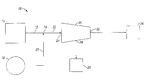
FIG. 1 is a schematic of an apparatus for injecting steam into an oil-based
drilling
fluid to enhance the removal of low gravity solids.
2

CA 02602685 2012-07-26
DETAILED DESCRIPTION
The claimed subject matter relates to an apparatus and method for removing low-
gravity solids from an oil-based drilling fluid. The oil-based drilling fluid
includes oil, water,
and solids in relative proportions consistent with used drilling fluid that
has been subjected to
preliminary processes to remove large solids from the fluid. The solids
remaining in the
drilling fluid typically include a percentage of high gravity solids and a
percentage of low
gravity solids. High gravity solids are those solids that are dense, as in
barite or hematite,
while low gravity solids are those solids that have a lower density man
barite. The oil and
water in the used drilling fluid are present in proportionate amounts, the
relationship between
them often being expressed as an oil-to-water ratio.
Referring to FIG. 1, the apparatus 10 includes a steam generator 18 and a
centrifuge
26. Oil-based drilling fluid to be treated is directed through a first line 12
from a tank 16 or
mud plant or another process to prepare the oil-based drilling fluid or
recovery. The steam
generator 18 provides steam to a second line 20. The second line 20 directs
the steam into
the first line 14 such that the steam and the drilling fluid are commingled in
a second portion
22 of the first line 14. In one embodiment, the steam injected has a
temperature of 320 to
350 degrees Fahrenheit. In one embodiment the steam is injected into the first
line in an
amount in the range of 0.25 to 0.4% by volume of mixture of the drilling fluid
and the steam.
The steam and drilling fluid mixture then continue through the first line 14
to the
centrifuge 26 through a centrifuge inlet 24. In one embodiment the commingled
steam and
drilling fluid is fed into the centrifuge inlet 24 at a feed rate of about 20
gpm.
The centrifuge 26 includes an internally located bowl (not shown) to which the
drilling fluid and steam mixture is directed. The bowl is rotated at a rate
sufficient to
separate solids entrained in the drilling fluid such that solids remaining in
the effluent are less
than 10% of the effluent. In one embodiment, the centrifuge is rotated at
about 1,800 RPM.
An internally located conveyor (not shown) directs solids towards a solids
discharge 28 from
the centrifuge 26 and collected M a cuttings box 30. The fluid and any
remaining solids are
directed to an effluent outlet 32 from the centrifuge 26 to a holding tank 34.
In one example, a typical drilling fluid was evaluated to determine its
properties. It
was found that the drilling fluid to be treated was 54.0% oil, 20.0 % water
and 26.0% solids.
The corrected high gravity solids = were 15.87% and the corrected low gravity
solids were
9.06%. To establish a baseline, the drilling fluid was subjected to
centrifugation alone. The
effluent from the centrifuge was evaluated and found to contain 8% solids,
wherein the
corrected high gravity solids were 3.57 % and the corrected low gravity solids
were 3.45%.
3

CA 02602685 2012-07-26
Steam was injected into the drilling fluid immediately prior to the inlet to
the
- centrifuge. The amount of steam injected was varied from 0.05 gpm to 0.10
gpm, while the
pressure was varied from 88 to 100 psi. The injection of steam into the
drilling fluid prior to
centrifugation changed the properties of the effluent from the centrifuge.
First, the
percentage of solids in the effluent was reduced to less than 6%. While the
percentage of
high gravity solids was reduced somewhat, it was found that low gravity solids
were nearly
eliminated from the effluent. The percentage of low gravity solids were in the
range of 0 to
1.01%.
One of skill in the art will appreciate that no chemicals have been added to
the
drilling fluid to facilitate removal of the solids. Thus, low gravity solids
may be eliminated
from drilling fluid to be reused by a process that is free of additional
expensive chemicals.
Further, the solids discharge from the centrifuge is free of polymers and
surfactants that are
often used to facilitate the removal of solids from drilling fluid to be
treated and used again.
While the claimed subject matter has been described with respect to a limited
number
of embodiments, those skilled in the art, having benefit of this disclosure,
will appreciate that
other embodiments can be devised which do not depart from the scope of the
subject
as set forth in the attached claims.
4

Representative Drawing
A single figure which represents the drawing illustrating the invention.
Administrative Status

2024-08-01:As part of the Next Generation Patents (NGP) transition, the Canadian Patents Database (CPD) now contains a more detailed Event History, which replicates the Event Log of our new back-office solution.

Please note that "Inactive:" events refers to events no longer in use in our new back-office solution.

For a clearer understanding of the status of the application/patent presented on this page, the site Disclaimer , as well as the definitions for Patent , Event History , Maintenance Fee  and Payment History  should be consulted.

Event History

Description Date
Maintenance Fee Payment Determined Compliant 2021-05-05
Inactive: Late MF processed 2021-05-05
Common Representative Appointed 2019-10-30
Grant by Issuance 2013-07-16
Inactive: Cover page published 2013-07-15
Pre-grant 2013-04-30
Inactive: Final fee received 2013-04-30
Notice of Allowance is Issued 2012-11-01
Letter Sent 2012-11-01
Notice of Allowance is Issued 2012-11-01
Inactive: Approved for allowance (AFA) 2012-10-30
Amendment Received - Voluntary Amendment 2012-07-26
Inactive: S.30(2) Rules - Examiner requisition 2012-02-03
Letter Sent 2011-04-26
Reinstatement Requirements Deemed Compliant for All Abandonment Reasons 2011-04-15
Deemed Abandoned - Failure to Respond to Maintenance Fee Notice 2011-04-11
Letter Sent 2011-03-01
Request for Examination Received 2011-02-22
Request for Examination Requirements Determined Compliant 2011-02-22
All Requirements for Examination Determined Compliant 2011-02-22
Inactive: Cover page published 2007-12-14
Inactive: Notice - National entry - No RFE 2007-12-12
Inactive: First IPC assigned 2007-10-27
Application Received - PCT 2007-10-26
National Entry Requirements Determined Compliant 2007-09-28
Application Published (Open to Public Inspection) 2006-10-19

Abandonment History

Abandonment Date Reason Reinstatement Date
2011-04-11

Maintenance Fee

The last payment was received on 2013-03-27

Note : If the full payment has not been received on or before the date indicated, a further fee may be required which may be one of the following

  • the reinstatement fee;
  • the late payment fee; or
  • additional fee to reverse deemed expiry.

Please refer to the CIPO Patent Fees web page to see all current fee amounts.

Owners on Record

Note: Records showing the ownership history in alphabetical order.

Current Owners on Record
M-I L.L.C.
Past Owners on Record
CATALIN IVAN
NEALE BROWNE
Past Owners that do not appear in the "Owners on Record" listing will appear in other documentation within the application.
Documents

To view selected files, please enter reCAPTCHA code :


To view images, click a link in the Document Description column. To download the documents, select one or more checkboxes in the first column and then click the "Download Selected in PDF format (Zip Archive)" or the "Download Selected as Single PDF" button.

List of published and non-published patent-specific documents on the CPD .

If you have any difficulty accessing content, you can call the Client Service Centre at 1-866-997-1936 or send them an e-mail at CIPO Client Service Centre.


Document
Description 
Date
(yyyy-mm-dd) 
Number of pages   Size of Image (KB) 
Abstract 2007-09-28 1 60
Representative drawing 2007-09-28 1 4
Claims 2007-09-28 2 72
Drawings 2007-09-28 1 6
Description 2007-09-28 4 252
Cover Page 2007-12-14 1 36
Description 2012-07-26 4 219
Claims 2012-07-26 2 69
Drawings 2012-07-26 1 7
Representative drawing 2013-06-19 1 5
Cover Page 2013-06-19 1 37
Reminder of maintenance fee due 2007-12-12 1 112
Notice of National Entry 2007-12-12 1 194
Reminder - Request for Examination 2010-12-14 1 119
Acknowledgement of Request for Examination 2011-03-01 1 176
Courtesy - Abandonment Letter (Maintenance Fee) 2011-04-26 1 173
Notice of Reinstatement 2011-04-26 1 164
Commissioner's Notice - Application Found Allowable 2012-11-01 1 162
Courtesy - Acknowledgement of Payment of Maintenance Fee and Late Fee (Patent) 2021-05-05 1 423
PCT 2007-09-28 2 72
Fees 2011-04-15 1 42
Correspondence 2013-04-30 1 37